FEC Heliports Worldwide HP0720 USB Zulu Dongle 915MHz User Manual Users manual
FEC Heliports Worldwide Limited USB Zulu Dongle 915MHz Users manual
Users manual
® Interleader Limited
HEMS-Star®
PC Controller Software - Installation and User Manual
Issue: 1.2 27th April 2016
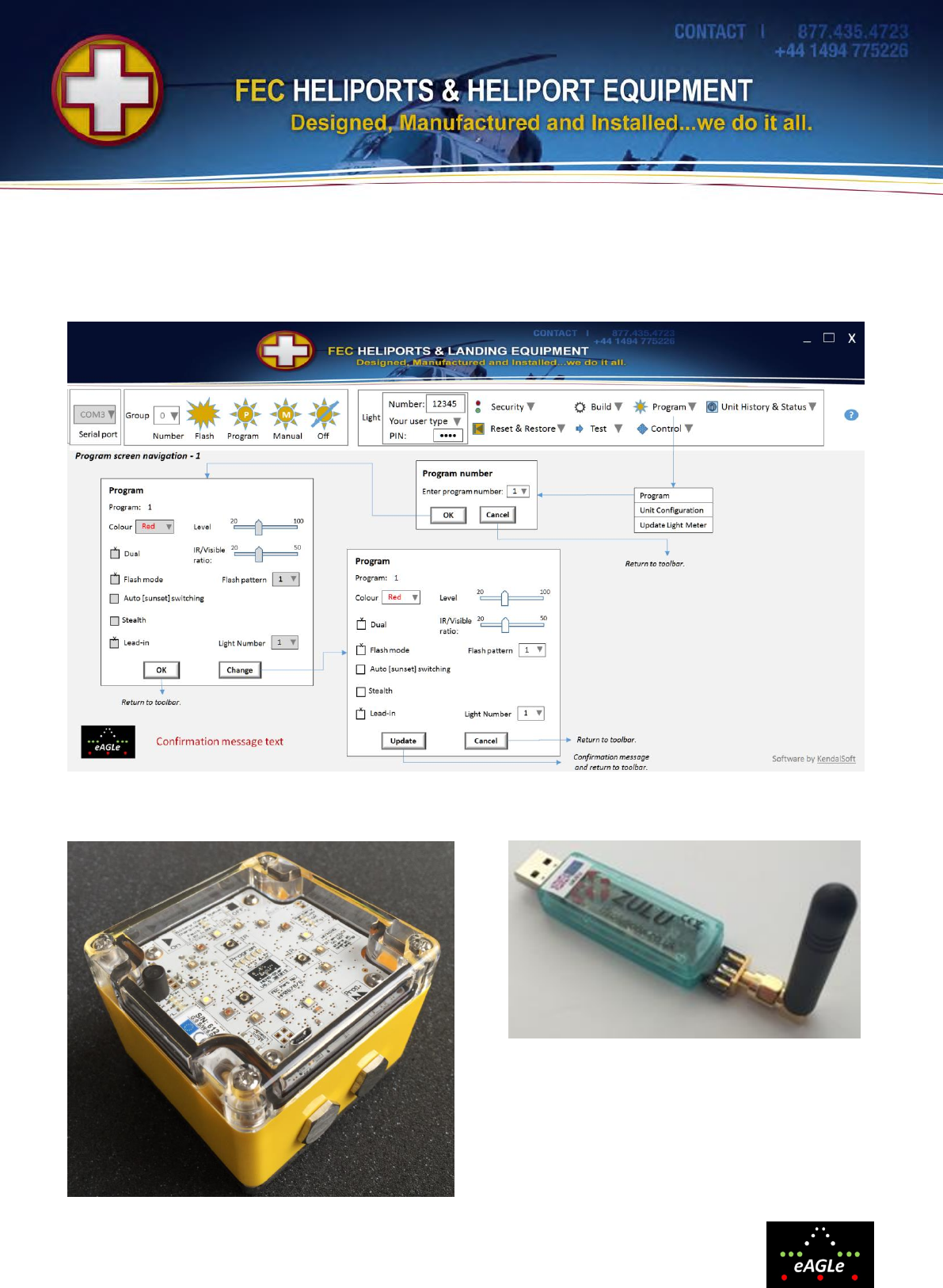
HEMS-Star® PC Controller Program Setting Logic
Zulu Dongle and Antenna
HEMS-Star®

© Interleader Limited 2016 2 of 16 27/04/2016
Document Revision
Issue
Date
Changes
1.0
21/02/2016
New Document
1.1
17/03/2016
Updated UHF Figures
1.2
27/04/2016
Corrected UHF table
Contents
1. Overview .......................................................................................................2
2. Zulu ‘Dongle’ Compliance Statements ...........................................................3
3. Installation .....................................................................................................4
4. Software Screen Sections .............................................................................6
5. Group Commands .........................................................................................7
6. Individual Commands ....................................................................................8
6.1 Security .........................................................................................................9
6.2 Unit Build Information ....................................................................................9
6.3 Program ........................................................................................................9
7. Appendix A: Flash Patterns ......................................................................... 14
8. Appendix B: UHF Radio Modem Specification ............................................. 15
1. Overview
The HEMS-Star® PC Controller Software (in this manual refered to as ‘the software’), in conjunction
with a Zulu ‘Dongle’, enables HEMS-Star® lights (in this manual refered to as ‘the lights’) to be
configured and controlled, either as individual lights or as a group.
To run the software requires:
1) The software
a. supplied on USB memory stick
b. updates available on-line for download
2) Zulu Dongle and Antenna
a. supplied in the carry/charging case
3) PC, Laptop or Tablet
a. Not supplied
b. Should be running Microsoft Windows 10 but has been shown to work on Microsoft
Windows 7 or later
c. Must have an accessible USB port
d. Must be connected to the internet during the installation process
The eAGLe logo and HEMS-Star® name are copyright of Interleader Limited 2016

© Interleader Limited 2016 3 of 16 27/04/2016
2. Zulu ‘Dongle’ Compliance Statements
USA
FCC Compliance WARNING
Changes or modifications to the transmitter not expressly approved by the manufacturer could void the
user's authority to operate this RF device.
FCC Compliance Statement
This device complies with Part 15 of the FCC Rules. Operation is subject to the following two
conditions:
1. This device may not cause interference, and
2. This device must accept any interference, including interference that may cause undesired operation
of the device.
USA-Federal Communications Commission (FCC)
This equipment has been tested and found to comply with the limits for a Class B digital device,
pursuant to Part 15 of FCC Rules. These limits are designed to provide reasonable protection against
harmful interference in a residential installation. This equipment generates, uses, and can radiate radio
frequency energy. If not installed and used in accordance with the instructions, it may cause harmful
interference to radio communications. However, there is no ensured specification that interference will
not occur in a particular installation. If this equipment does cause harmful interference to radio or
television reception, which can be determined by tuning the equipment off and on, the user is
encouraged to try and correct the interference by one or more of the following measures:
• Reorient or relocate the receiving antenna.
• Increase the distance between the equipment and the receiver.
• Connect the equipment to outlet on a circuit different from that to which the receiver is connected.
• Consult the dealer or an experienced radio/TV technician for help.
Any changes or modifications not expressly approved by the party responsible for compliance could
void the user’s authority to operate the equipment.
Europe
This device carries the CE marking showing it has been tested and shown to be in compliance with
relevant EU standards.

© Interleader Limited 2016 4 of 16 27/04/2016
3. Installation
Before beginning installation make sure you have:
1) Fully charged lights
2) PC with Windows 10 (has been shown to work on Windows 7 or later (The software will not
run on any earlier version of Windows, Apple iOS or Android devices)
3) Access to the internet with a fast connection
Installing the Zulu Dongle
Make sure that the PC is working and has access to the internet. Carefully extract the dongle and
antenna from the foam of the carry case by gently pulling vertically. Do not provide any lateral force as
this may damage either unit. Screw the antenna to the dongle (finger tight only).
Plug the dongle into an appropriate USB socket with the antenna pointing upwards. Windows will
detect that new hardware has been detected (and advise this in a pop-up window) and will install the
relevant drivers for the dongle automatically (again advised in a pop-up window). When the dongle
software is ready for use, proceed to installing the software.
Material on the USB Memory Stick
There are a number of folders and files on the USB Memory Stick containing:
Application Files
The executable code.
Battery Data
Manufacturers declaration about the battery
HEMS-Star Software
Software running the lights
KFC Software
Software for the optional Key Fob Controller
Labels
Battery shipping labels
Manuals
HEMS-Star summary (flier in case)
HEMS-Star manual (this document)
HEMS-Star PC Controller manual
Key Fob Controller manual
Videos
Short videos showing basic operations
HEMS-Star PC
Controller V1.1
A manifest containing information about the
software.
Setup
Setup file for PC Controller Software
It is recommended that you copy all of the files on the USB memory stick to your PC’s hard drive
However you organise the copied files, ensure that the following are all together, at the same level, in
the same directory (C:\Downloads recommended):
Folder: Application Files
Manifest File: PC Controller Software V1.01
Setup File: Setup.exe

© Interleader Limited 2016 5 of 16 27/04/2016
Installing PC Controller Software
The software uses Microsoft .Net Framework v4.6 components which are included with Windows 10.
If you are running an earlier version of Windows, at the time of installation, these components may
download automatically but if not you will need to download them manually. Note that this is a large
download and even with a fast internet connection will take some tens of minutes and will require a re-
start of the PC to take effect.
To install the software:
1) Shut down all other applications running on your PC
2) Uninstall any previous version of the PC Controller application
a. Select: Windows key, All apps, double click on HEMS Star PC Controller and select
uninstall
3) Plug in your dongle and switch on a light
4) Switch off protection software such as Avast, McAfee completely
5) Run the setup.exe file
a. This can either be from the memory stick or from the location you copied the files to
b. If you get a screen displayed saying this is risky software and a ‘Don’t install’ button then
select ‘More Info’ and then press ‘Install anyway’.
6) A ‘Publisher cannot be verified’ screen will be displayed – select ‘Install’.
7) The software will install and appear thus:
If it does not appear at all, repeat the process above ensuring that all steps are followed exactly.
On narrower screens, the menu area may appear trunctacted from the right (for example the Help area
may not be visible). This is quite normal and is managed by use of the drop-down menus (see later
sections).
Operational Note:
Check that you have the correct serial number, the battery is properly charged and the light switched
on before running the software or you will receive various failure and time-out messages.
Also, this version of the software can experience time-outs when communicating with the lights. This is
being addressed for future releases of the software.
© Interleader Limited 2016 6 of 16 27/04/2016
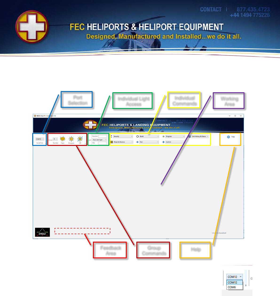
4. Software Screen Sections
The screen of the software is divided into a number of sections as described below:
Port Selection
When the dongle was installed on you PC, Windows allocated it the next availlable
COM port. The first thing to do is to select the correct port for the Zulu dongle. Use the
drop down menu to see what ports are available. In this example COM12 and COM6
are available. If unsure which is the correct one, select each in turn and issue a Group
Command (see later section).
Group and Individual Light Commands
Lights respond to both
1) Group Commands (All lights of the same group do the same thing e.g. run program 3), and
2) Individual Commands (Only the correctly addressed light responds to a specific command)
The following sections deal with each of these.
Port
Selection
Group
Commands
Individual Light
Access
Individual
Commands
Help
Working
Area
Feedback
Area
© Interleader Limited 2016 7 of 16 27/04/2016
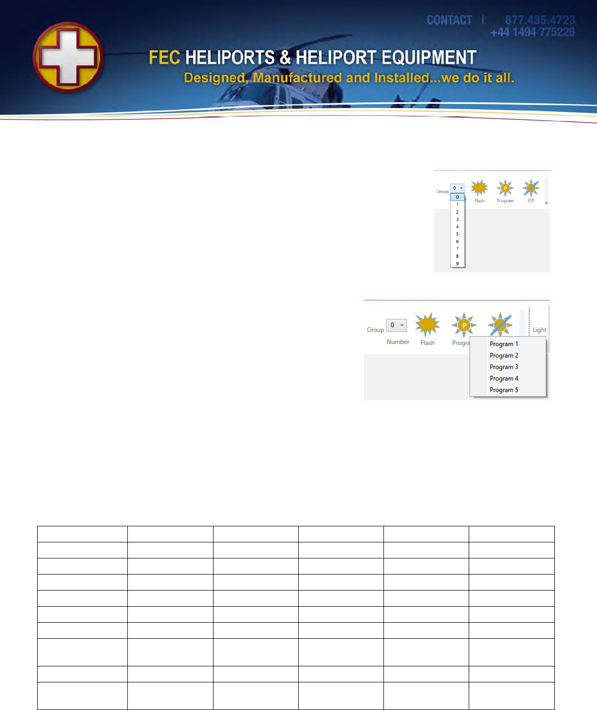
5. Group Commands
The Group Commands are the simplest and, once the lights are set as you
want them, the only commands you are likely to use. It is essential to first
select the group of lights to be controlled.
Use the drop down menu to view and select the group required.
Note that all lights are shipped with Group 0 as the default. If you have not
changed this then the default selection may be left as it is.
Basic Group Commands
There are three basic group commands:
1) Flash the lights (each time the icon is pressed)
2) Select and turn on a program
a. Click the program icon and the drop-down menu
will appear
b. Select the desired program
3) Turn the light off (puts it in wireless ‘Standby’ mode)
Note: For any of the above to work, the lights must already have been turned on with the magnetic key
(see main manual). Turning the lights off through group commands puts them in wireless Standby
mode. To turn them off, use the magnetic key.
Default Program Settings
The default program settings are (see Appendix A for flash patterns):
Program
1
2
3
4
5
Colour
Green
Green
Green
Red
White
Level
60%
60%
60%
80%
100%
Single/Dual
Single
Single
Dual
Single
Single
Dual Ratio
30%
30%
50%
30%
30%
Mode
Steady
Steady
Steady
Flash
Flash
Flash Pattern
1:3
ID Single
ID Dual
ID Dual
Morse ‘H’
Normal/Sunset
Switching
Normal
Sunset
Normal
Normal
Normal
Stealth
Normal
Normal
Normal
Normal
Normal
Comment
Shipping setting
Warning IR
Emitted
Note that greyed-out figures above mean that these are set in the program memory but ignored
because of the other settings. e.g. in program 1 the dual ratio is set at 30% but is ignored because
program 1 is set to Single Mode.
© Interleader Limited 2016 8 of 16 27/04/2016
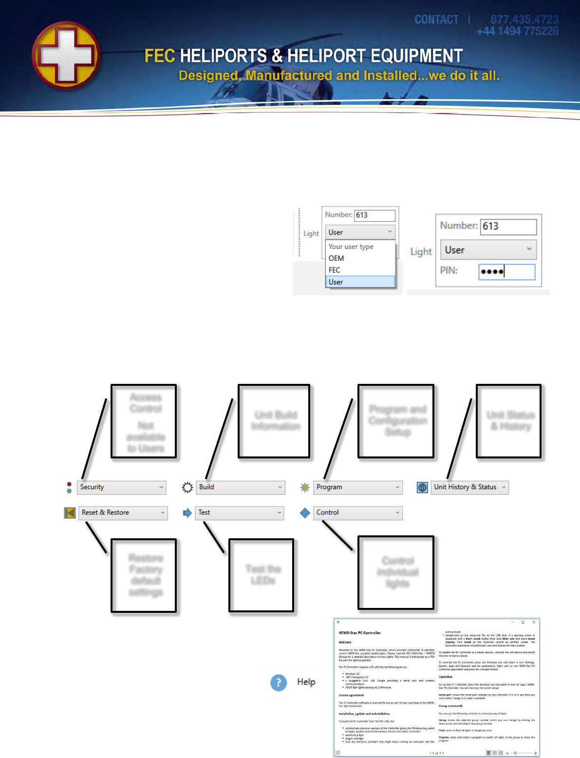
6. Individual Commands
Individual Commands will usually only be used during setup or testing activities and are specific to one
light at a time.
Accessing a Light
First enter the light Serial Number (printed on the
label inside each light). In this example it is 613.
Select the User Type from the drop-down menu. In
this case: User
Then enter the User PIN number. The default PIN
number is 0000. FEC can change this PIN number
and in future releases of software this will also be a user changeable item.
Once the correct credentials are entered they are maintained until changed allowing all of the Individual
Commands for a light to be used. Only the light number needs to be changed to move to another light.
Individual Command Functions
The functions that can be performed are grouped as follows (details in later sections):
Help
Pressing the Help key brings up simple text
based help.
This will be expanded in subsequent
releases of the software.
Access
Control
Not
available
to Users
Unit Build
Information
Program and
Configuration
Setup
Unit Status
& History
Restore
Factory
default
settings
Test the
LEDs
Control
individual
lights
© Interleader Limited 2016 9 of 16 27/04/2016
6.1 Security
This option is not currently available to Users.
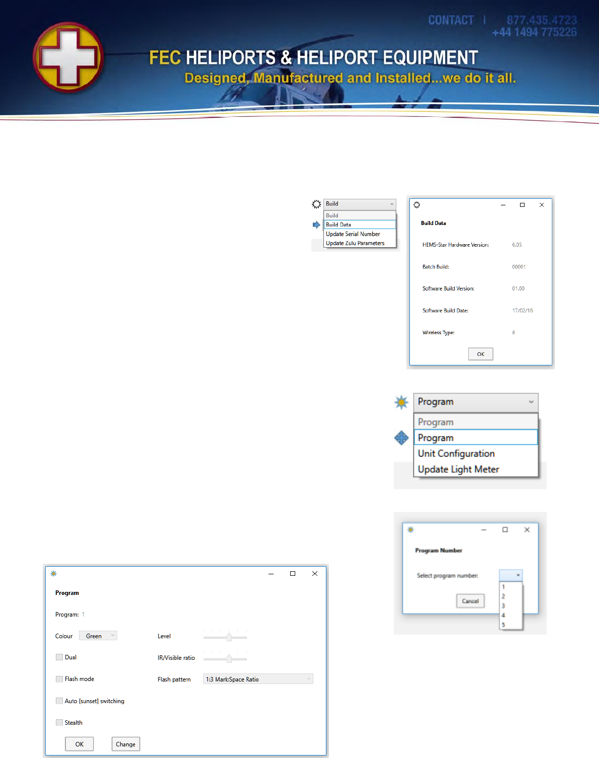
6.2 Unit Build Information
The only option available to Users is the Build Data
option which returns details of the unit (useful for
diagnostic purposes)
6.3 Program
The Program menu has further options:
Program: To check the current settings of the programs
(1-5) and to make changes.
Unit Configuration: To check and make to the configuration
settings which are common to all programs, and
Update Light Meter: To calibrate the internal light meter
Program
Selecting Program brings up a screen requesting the program to be
accessed. Use the pull-down menu to select. In this example we are
going to select program 1.
The software reads the setup of program 1
from the light and displays it. This is the
default setting for program 1: Steady
Green, 60% with no other attributes
selected. Note that all of the settings, even
if not active are visible (see earlier
comment. Click OK if no changes are
required or Change to do so.
© Interleader Limited 2016 10 of 16 27/04/2016
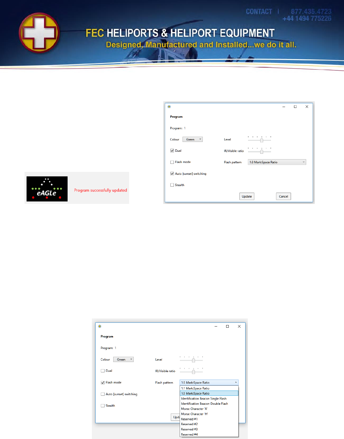
If it is required to set program 1 to Dual mode (both the visible and IR LEDs on at once) and for the
light to perform automatic switch on at sunset, then check the relevant boxes as shown below and click
Update.
Confirmation (or not) that the change has happened is provided at the bottom left hand side of the
screen (above left).
Notes:
1) Setting the visible light level to its lowest two levels sets the level to 20%. This will corrected in
later releases
2) Some combinations (e.g. IR selected as the Colour with Dual Mode) make no logical sense and
will be rejected.
3) Once the change has been made it is stored permanently in the light until changed again.
4) If the light is being programed in Standby mode, it will turn on the currently selected program
after the update.
Flash Patterns
Selecting flash mode will allow the drop down menu of patterns available:
© Interleader Limited 2016 11 of 16 27/04/2016
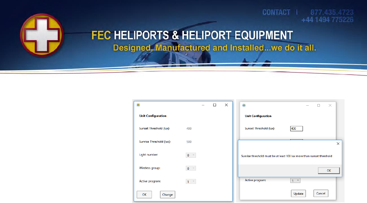
Configuration
Sunset & Sunrise
From the main Program menu,
clicking Configuration will bring
back the lights configuration
settings common to all programs:
The light level at which the light
will autmatically switch on or off
are defined by the Sunset and
Sunrise Threshold settings.
The default figures shown have
proven to be suitable for most
applications but if local
conditions dictate a change, click
update and then enter new figures to either or both.
Note that if an attempt is made to set figures that are less than 100Lux apart (Sunrise being higher than
Sunset) the software will warn you about this and prevent the setting (upper right).
This is to ensure that the lights do not ‘hunt’ on and off due to the inevitable small changes in light level
that occur.
Light Number
Note that the Light Number is NOT the serial (identification) number of the light but the position at
which the light will flash when it receives a ‘Flash’ command as part of a series of lights.
All lights are shipped with the light number 0, meaning that the instant they receive a flash command
they will flash. If a lead-in light pattern is required (sequence of ‘running’ lights) then set the required
number of lights to a series (e.g. 0, 1, 2, 3, 4) for a sequence of 5 lights.
Wireless Group
All lights belong to a Group and respond to group commands addressed to that group. All lights are
shipped set to Group Group 0. If multiple sets of lights are to be independently controlled, then set
each group to a different group number and remember to change the group number in the Group
Command area to the group to be controlled.
Active Program
Active program indicates the program that is currently selected and which the light will come on at
when turned on from sleep with the magnetic key. Programs 1-5 can be selected.
Update Light Meter
This command should be used with caution.
The light’s internal light meter can be calibrated. To do this place the light and a precision light meter in
the lit area (at around 400Lux). Note the reading on the light meter and enter it into the box and click
update. The light will use the provided value to calibrate its internal meter. The value can be checked
using the the Unit Status command (next section).
© Interleader Limited 2016 12 of 16 27/04/2016
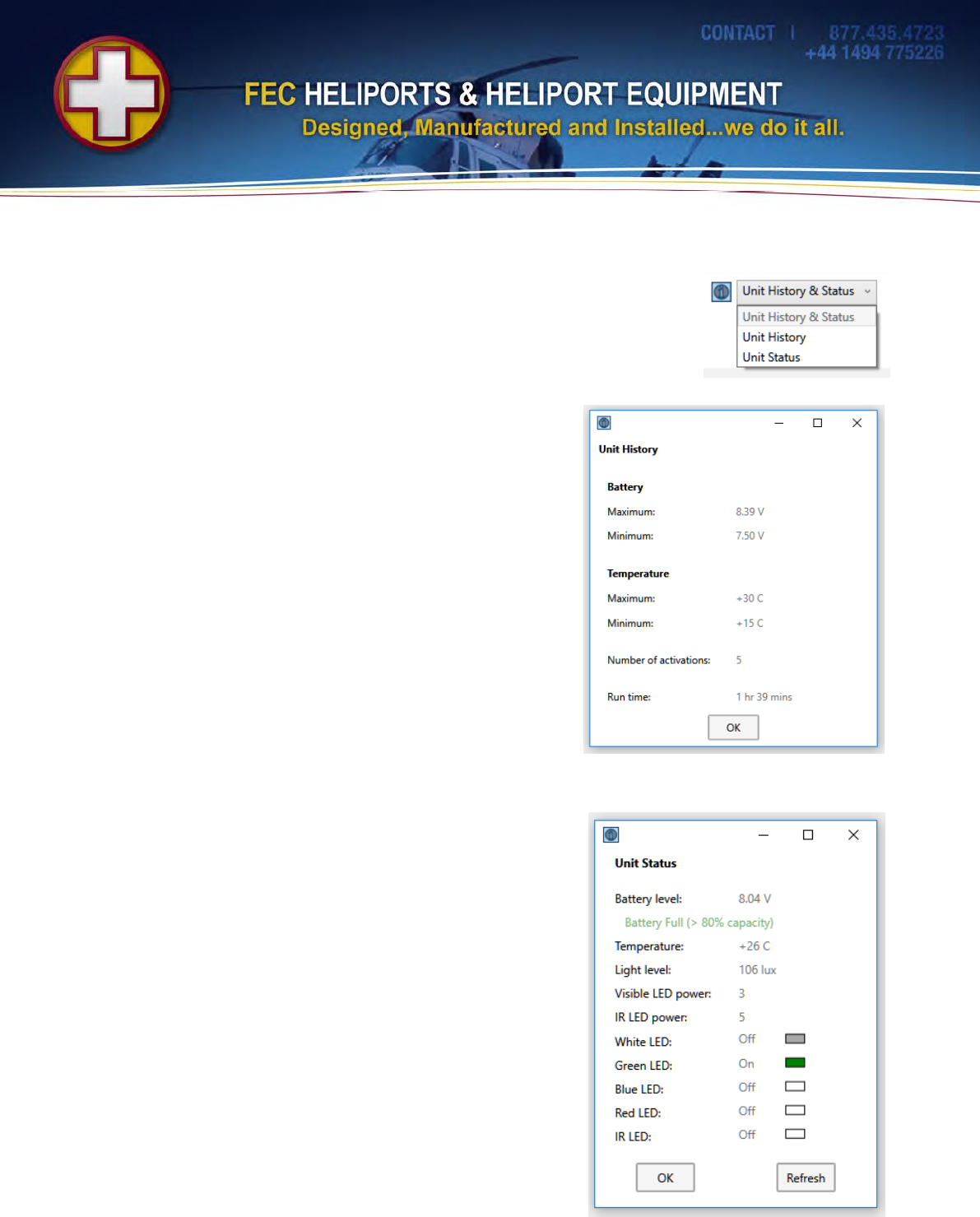
7. Unit History and Status
The Unit History and Status can be accessed from the top menu:
Unit History
HEMS-Stars build a history log for diagnostic purposes and is
a read-only function.
The data returned includes:
1) the maximum and minimum battery voltage detected
2) the maximum and minimum temperature of the unit
3) the number of times the light has been activated
(turned on with the magentic key), and
4) the total running time of the light in hours and minutes
Unit Status
The current status of the light can be accessed.
This light is showing that the battery is nearly fully charged, the
temperature inside the case is 26C and the light level 103Lux.
The Visible and IR power levels are shown as 3 (60%) and 5
(50% if Visible level) respectively. (Note future versions of
software will show the decoded percentage figures).
Only the Green LEDs are On indicated by the text ‘On’ and the
colour filled box.
Note the status can be obtained at any time but because ii is
an instantaneous reading, if the light is in standby or between
flashes then the LED status will show Off (since at that instant
they are).
This option is useful for checking that the light meter
calibration cycle in the previous section has been successful. If
it has, the reading returned from the light and the calibration
light meter reading will be the same. Note that the light meter
in the light is only accurate around the set value (approx
400Lux).
© Interleader Limited 2016 13 of 16 27/04/2016
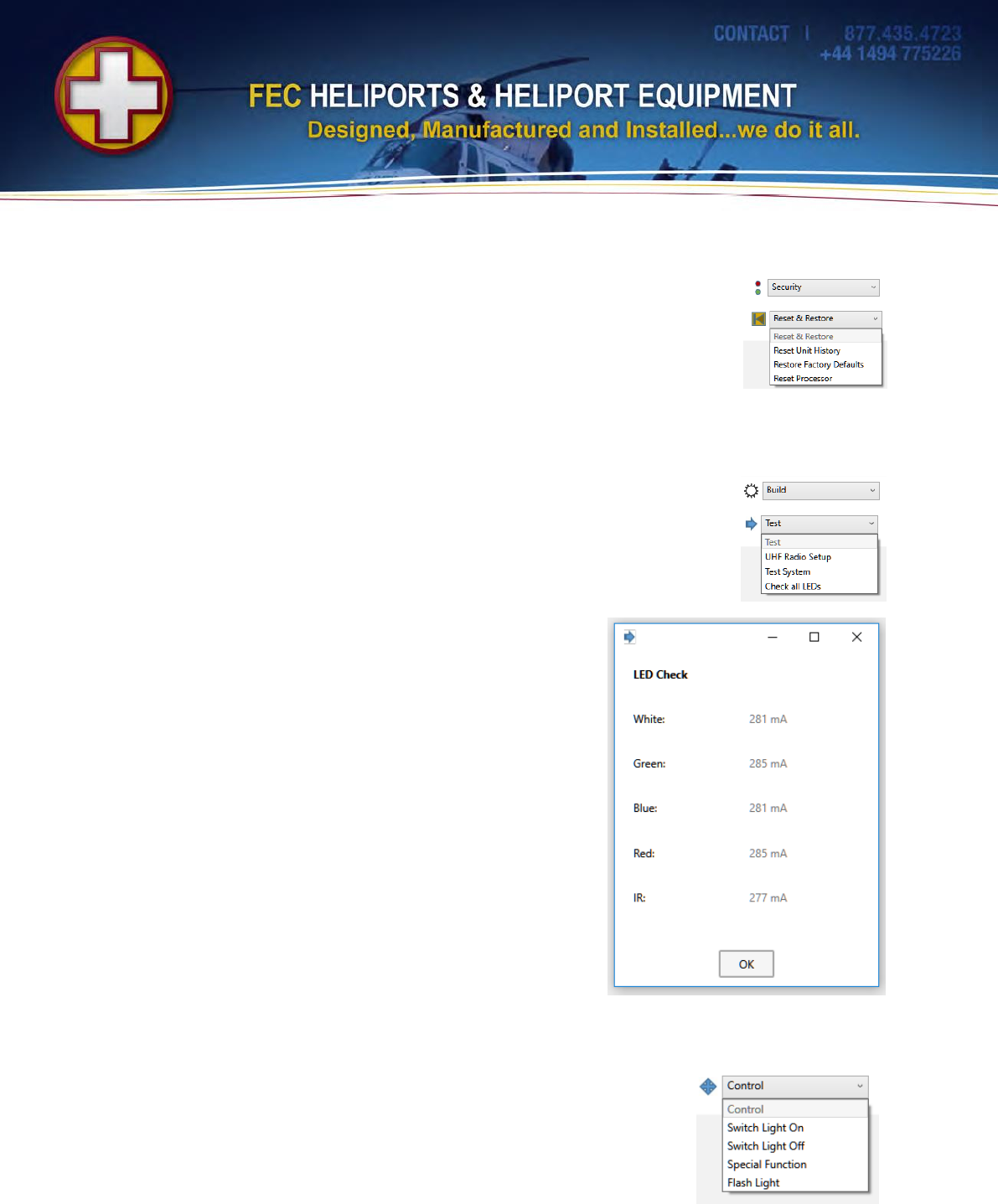
8. Reset & Restore
Of the menu options, only the Reset Factory Defaults option is available to
Users.
The program settings as shown earlier are applied along with all of the
configuration and calibration data. All user settings are lost.
9. Test
Of the menu options, only Check the LEDs option is available to users.
WARNING – clicking this option will cycle all of the LEDs (including IR) through
a test routine that drives the LEDs harder than the normal 100% setting.
Do not look at the LEDs during this test and note that this test takes a number of
seconds to perform – this is quite normal and to be expected.
All of the LEDs light in turn (White, Green, Blue, Red, Infra Red)
and then the results will be returned.
The normal range of currents is between 260 and 290mA for
the visible LEDs (and be similar for all of them) and between 10
and 20mA lower for the Infra-Red.
10. Control
It is possible to control individual lights with the same functions as the
group commands.
Selecting Switch Light On will ask which program to set on (as per the
Group Command).
Special Function is a reserved command for future use.

© Interleader Limited 2016 14 of 16 27/04/2016
11. Appendix A: Flash Patterns
The following flash patterns are available:
Mode
Description
Timing
Flash Rate
0
1:1 Mark:Space Ratio
On – 250mS
Off - 250ms
120 Flashes / Minute
1
!:3 Mark:Space Ratio
On - 250mS
Off - 750mS
60 Flashes / Minute
2
Identification Beacon
Single Flash
On – 250mS
Off – 1750mS
30 Flashes / Minute
3
Identification Beacon
Double Flash
On – 250mS
Off – 100mS
On – 250mS
Off – 1400mS
30 Frames (of two flashes) / Minute
4
Morse Character ‘X’
On – 300mS
Off – 100mS
On – 100mS
Off – 100mS
On – 100mS
Off – 100mS
On – 300mS
Off – 900mS
30 Characters / Minute
5
Morse Character ‘H’
On – 100mS
Off – 100mS
On – 100mS
Off – 100mS
On – 100mS
Off – 100mS
On – 100mS
Off – 1300mS
30 Characters / Minute
6
Reserved #1
7
Reserved #2
8
Reserved #3
9
Reserved #4

© Interleader Limited 2016 15 of 16 27/04/2016
12. Appendix B: UHF Radio Modem Specification
The Modem has the following specification.
Parameter
Value
UK/EU/ROW 868MHz
USA 915MHz
Manufacturer:
RF Solutions Ltd. UK
RF Solutions Ltd. UK
Modem Type:
ZULU-2-M868-SO
ZULU-2-M915-SO
Nominal Frequency Band:
868MHz
915MHz
Frequency Options:
868.400, 868.900, 869.450,
869.600 & 869.800MHz
915.00, 915.09, 915.18 & 915.27MHz
Frequency Set to:
869.450MHz
915.00 – 915.27MHz
Bandwidth per Channel:
100kHz
90kHz
Deviation:
45kHz
45kHz
Power Output Set
100mW (20dBm)
0.74mW (-1.3dBm)
Receiver sensitivity:
Max –121dBm (-102dBm (Max) to -
109dBM (Min) at 56kbps)
Max –121dBm (-102dBm (Max) to -109dBM
(Min) at 56kbps)
PC Controller Range:
Up to 2km depending on RLC aerial
positioning and terrain
TBC
Addressing:
24bit secure data protocol
24bit secure data protocol
Addressing Schema:
One to Many
One to Many
RF Baud Rate:
56kbps
56kbps
Modem Data Rate:
19.2kbps
19.2kbps
Modulation:
Frequency Shift Keying (FSK)
Frequency Shift Keying (FSK)
Operating Temperature:
-40C to +85C
-40C to +85C
Compliance:
CE (see table below)
FCC Compliance is to 47 CFR part 15.249
RF Channel Selection
The EU standard sets maximum power transmission limits dependent on frequency, bandwidth and
application. A rough guidance applicable to the ZULU channel numbers is given below
Channel Number
Frequency Centre (MHz)
EU Power Allowance
mW/dBm
Notes
0
868.400
25/14
Applicable standard -
EN300-220
1
868.900
25/14
2
869.450
100/20
3
869.600
100/20
4
869.800
25/14
All specifications are manufacturer’s data

© Interleader Limited 2016 16 of 16 27/04/2016
End of
Document