FISHERPAYKEL Dishwasher Manual L0906175
DD24DCX6-88527A DD24DCX6-88527A FISHER & PAYKEL DISHWASHER - Manuals and Guides L0906175 View the owners manual for your FISHER & PAYKEL DISHWASHER #DD24DCX688527A. Home:FISHER & PAYKEL:/ Dishwasher Parts:FISHER & PAYKEL dishwasher parts:#DD24DCX688527A FISHER & PAYKEL dishwasher parts:#DD24DCX688527A FISHER & PAYKEL dishwasher manual
User Manual: FISHERPAYKEL FISHERPAYKEL Dishwasher Manual FISHERPAYKEL Dishwasher Owner's Manual, FISHERPAYKEL Dishwasher installation guides
Open the PDF directly: View PDF ![]() .
.
Page Count: 8
(1,1) -1- 599618C DD24D install A2 USCA.indd 15/4/09 10:01:39 AM
Importand
SAVETHESEINSTRUCTIONS
lh_÷ mocDIs shown in thLs docum_÷nt mc2y not b_÷c2vc2ilc2bl_÷in c_ll mc2rk_÷ts c_nd c2r_÷.subj_÷ct to chc2ng_÷ c2t c2ny tim_÷, f::or curr_÷nt cDtoi/s c2bout mocDI c2nd sp_÷cificotion c2vc2ilc2bility in your country, pl_÷c2.s_÷go to our
w_÷bsit_÷ www.fish_÷rpoykd.comor contoct your /ocol FTsh_÷r& Poy£÷ld_÷ol_÷r.
SAFETYAND WARNINGS
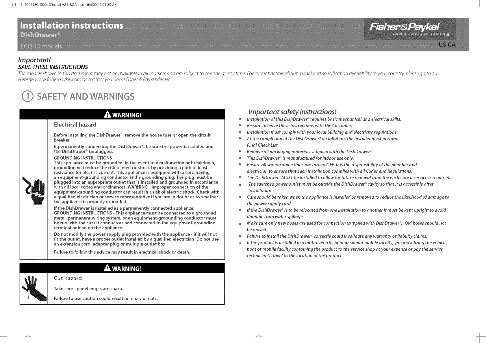
Electrical hazard
Before installing the DishDrawe¢ _, remove the house fuse or open the circuit
breaker.
If permanently connecting the DishDrawe¢ _,be sure the power is isolated and
the DishDrawer _ unplugged.
GROUNDmNG mNSTRUCTmONS
This appliance must be grounded. [n the event of a malfunction or breakdown,
grounding will reduce the risk of electric shock by providing a path of least
resistance for eBectric current. This appBiance is equipped with a cord having
an equipment-grounding conductor and a grounding plug. The plug must be
plugged into an appropriate outlet that is installed and grounded in accordance
with all local codes and ordinances. WARNmNG - Improper connection of the
equipment-grounding conductor can result in a risk of electric shock. Check with
a qualified electrician or service representative if you are in doubt as to whether
the appliance is properly grounded.
[f the DishDrawer is installed as a permanently connected appliance:
GROUNDmNG INSTRUCTIONS °This appliance must be connected to a grounded
metal, permanent wiring system, or an equipment=groounding conductor must
be run with the circuit conductors and connected to the equipment°grounding
terminal or lead on the appliance.
Do not modify the power supply plug provided with the appliance - if it will not
fit the outlet, have a proper outlet installed by a qualified electrician. Do not use
an extension cord, adapter plug or multiple outlet box.
Failure to follow this advice may result in electrical shock or death.
Cut hazard
Important safety instructions!
installation of this DishDrawer _requires basic mechanical and electrical skills.
Be sure to leave these Instructions with the Customer.
installation must comply with your local building and electricity regulations.
Atthe completion of the DishDrawer _installation, the Installer must perform
Final Check List.
Remove all packaging materials supplied with the DishDrawer%
This DishDrawer _ is manufactured for indoor use only.
Ensure all water connections are turned OFF. It is the responsibility of the plumber and
electrician to ensure that each installation complies with all Codes and Regulations.
The DishDrawer_ MUST be installed t_ a_wf_rfuture rem_val fr_m the enc_sure if service is required.
The switched power outlet must be outside the DishDrawer _ cavity so that it is accessible after
installation.
Care should be taken when the appliance is installed or removed to reduce the likelihood of damage to
the power supply cord.
If the DishDrawer _is to be relocated from one installation to another it must be kept upright to avoid
damage from water spillage.
Make sure only new hoses are used for connection (supplied with DishDrawerC% Old hoses shouM not
be reused.
Failure to install the DishDrawer _correctly could invalidate any warranty or liability claims.
If the product is installed in a motor vehicle, boat or similar mobile facility, you must bring the vehicle,
boat or mobile facility containing the product to the service shop at your expense or pay the service
technician_ travel to the location of the product.
Take care =panel edges are sharp.
Failure to use caution could result in injury or cuts.
I (1,2) -1-599618C DD24D install A2 USCA.indd 15/4/09 10:01:39 AM
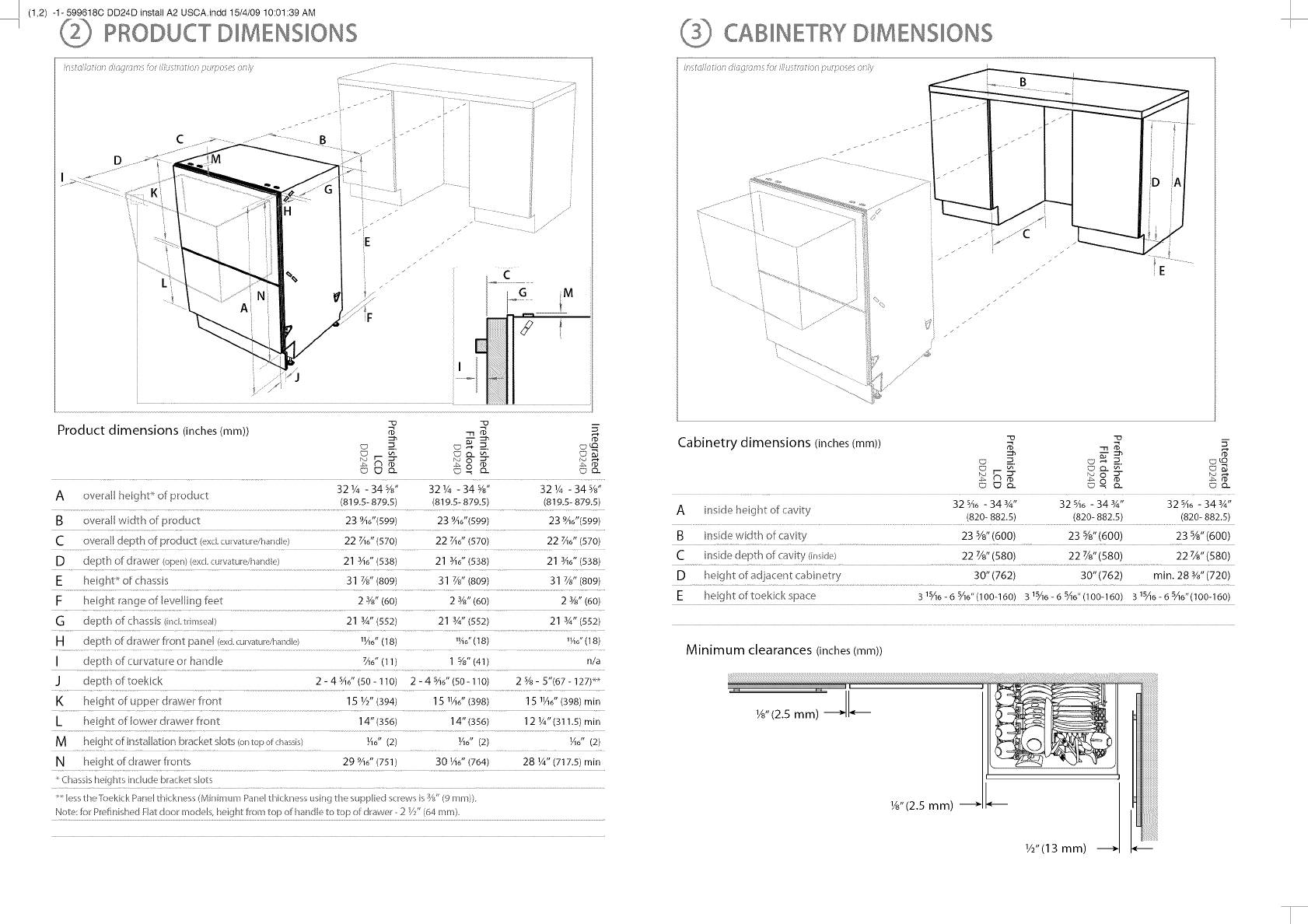
PRODUCT D MENS ONS
[,_OJ/ [[(?1 (]'J (1:)?; OFJ/JU 1: [J(?[ _? J_ C; 'J (?1)
Product dimensions (inches (mm)) _ m__ $,
c_- c_ ° _- c_-
A ove[al heght_ofprodu t 321/4 -34%" 321/4 -345/d '321/4 -34%"
(819.5- 879.5) (819.5- 879.5) (819.8- 879.5)
BoveraJl wdth of product 23 946"(599) 23 946"(599) 23 946"(599)
C overall depth of product (exd curvature/handJe) 22 _d' (570) 22 _d' (570) 22 _d' (570)
adepth of drawe_ (open)(exc[curvaturdha/die) 21 sad' (538) 21 _6" (538) 21 34d' (538)
E heght_of chassis 31 7/8"(809) 31 7/8"(809) 31%"(8o9)
Fheight range of eveJling fe_-_t 2 3/8"(60) 2 3/8"(60) 2 s/8"(60)
Gdepth of chassis (incLtrimseal) 21 3A"(552) 21 Y4"(552) 21 3A"(552)
mdepth of drawer front panel (exd.curvature,!_andle) 1H6"(18) "/id'(18) "/i?'(18)
I depth of curvature o_ handle 7A6"(11) 1%" (41) n/a
Jdepth of toekick 2 - 4 SAo"(50 - 110) 2 - 4 sAo"(50- 11o) 2 % - 5"(67 - 127)_*
K height of upper @awe font 151/2" (394) 15 11A6"(398) 15 1¼6"(398) min
h heightof owerdrawerfront 14"(356) 14"(356) 12 1/4"(311.5)min
Mheghtofinstallation bracke sots(onlopofchasss) ¼6" (2) lk6" (2) ¼6" (2)
Nheght of drawer fronts 29 %6" (751) 30 1A6"(764) 28 _A"(717.5) rain
C} assishe ghts nchde bracket sots
Besst} eTbekick Pa_e[ _ ckness(Mr mira Panel h cknessus_g tt_esupplied screwsisW' (9 ram)),
Note:lot Prr:,finishedFJa_door models, height from top of hande _o_op of drawe --2 V_"(64 mm)
_E
Cabinetry dimensions (inches (mm)) _ m _
32 SA6- 34 sA" 32 sA6- 34 sA" 32 sA6- 34 Y4"
Ainsde heig ht of cavity (820- 882.5) (820- 882.5) (820- 882.5)
Binside width of cavity 23 s/8" (600) 23 s/8"(600) 23 s/8"(600)
C i "_sde depth of avity (rlSkk,) 22 7/8"(580) 22 7/8"(580) 22 7/8"(580)
D heght of adjace t_ cabinetry 30" (762) 30" (762) min. 28 s/d' (720)
Eheightoftoekickspace 315A6-65A6"(lO0-160) 315A6-65A6"(lO0-160) 315A6-65A6"(lO0-160)
Minimum clearances (inches(mm))
L(2,1) -1- 599618C DD24D install A2 USCA.indd 15/4/09 10:01:39 AM
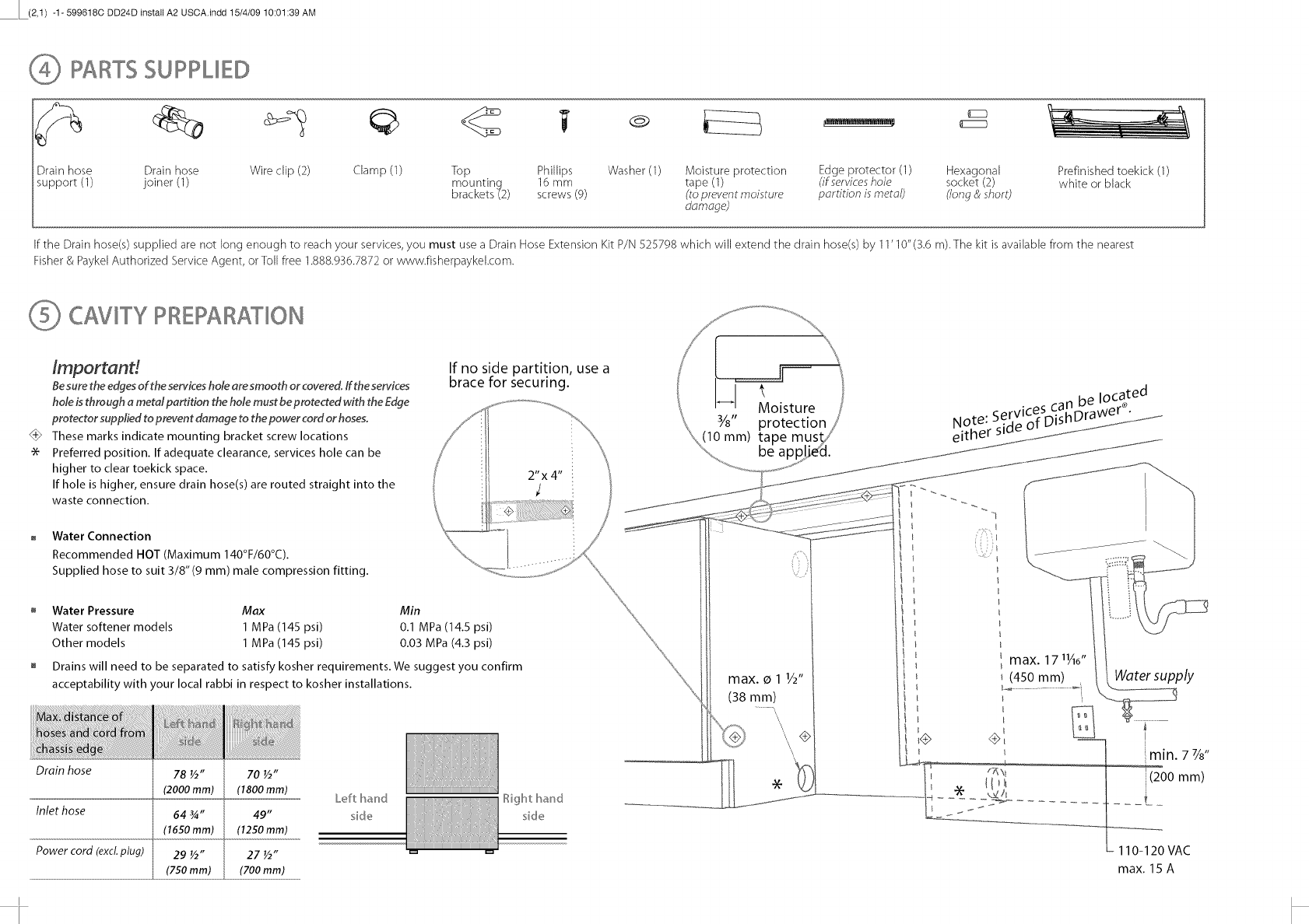
PARTS SUPPUED
Drain hose Drain hose Wire clip (2) Clamp (1) Top Phillips Washer (1) Moisture protection Edge protector (1) Hexagonal Prefinished toekick (I)
support (1) joiner (1) mounting 16 mm tape (1) (if serviceshole socket (2) white or black
brackets (2) screws (9) (to prevent moisture partition ismetal) (long & short)
d_m_ge)
If the Drain hose(s) supplied are not long enough to reach your services, you must use a Drain Hose Extension Kit P/N 525798 which will extend the drain hose(s) by 1I' 10"(3.6 m).The kit isavailable from the nearest
Fisher& Paykel Authorized Service Agent, or Toll free 1.888.936.7872 or www.fisherpaykekcom.
CAVKY PREPARATION
$6
Importand
Besure the edgesof the serviceshole aresmooth orcovered, ff the services
hole isthrough a metal partition the hole must be protected with the Edge
protector supplied to prevent damage to the power cord or hoses.
These marks indicate mounting bracket screw locations
Preferred position. If adequate clearance, services hole can be
higher to clear toekick space.
If hole is higher, ensure drain hose(s) are routed straight into the
waste connection.
Water Connection
Recommended HOT (Maximum 140°F/60°C).
Supplied hose to suit 3/8" (9 ram) male compression fitting.
If no side partition, use a
brace for securing.
Water Pressure Max Min
Water softener models 1 MPa (145 psi) 0.1 MPa (14.5 psi)
Other models 1 MPa (145 psi) 0.03 MPa (4.3 psi)
Drains will need to be separated to satisfy kosher requirements. We suggest you confirm
acceptability with your local rabbi in respect to kosher installations.
Drain hose
Inlet hose
Power cord (excl.plug)
78 ½" 70 ½"
(2000mm) (1800 ram)
64 ¾"
(1650 mm)
29 ½"
(750 mm)
49"
(1250 ram)
27 ½"
(700 mm)
Left hand
side
Right hand
side
(10 mm) ta
max. o 1 1/2"
(38 mm)\
Water supply
J
i
_min. 7 Ys"
(200 mm)
max. 17 11A6"
(450 mm)
z?i\t
110-120VAC
max. 15 A
L(2,2) -1- 599618C DD24D install A2 USCA.indd 15/4/09 10:01:39 AM
I
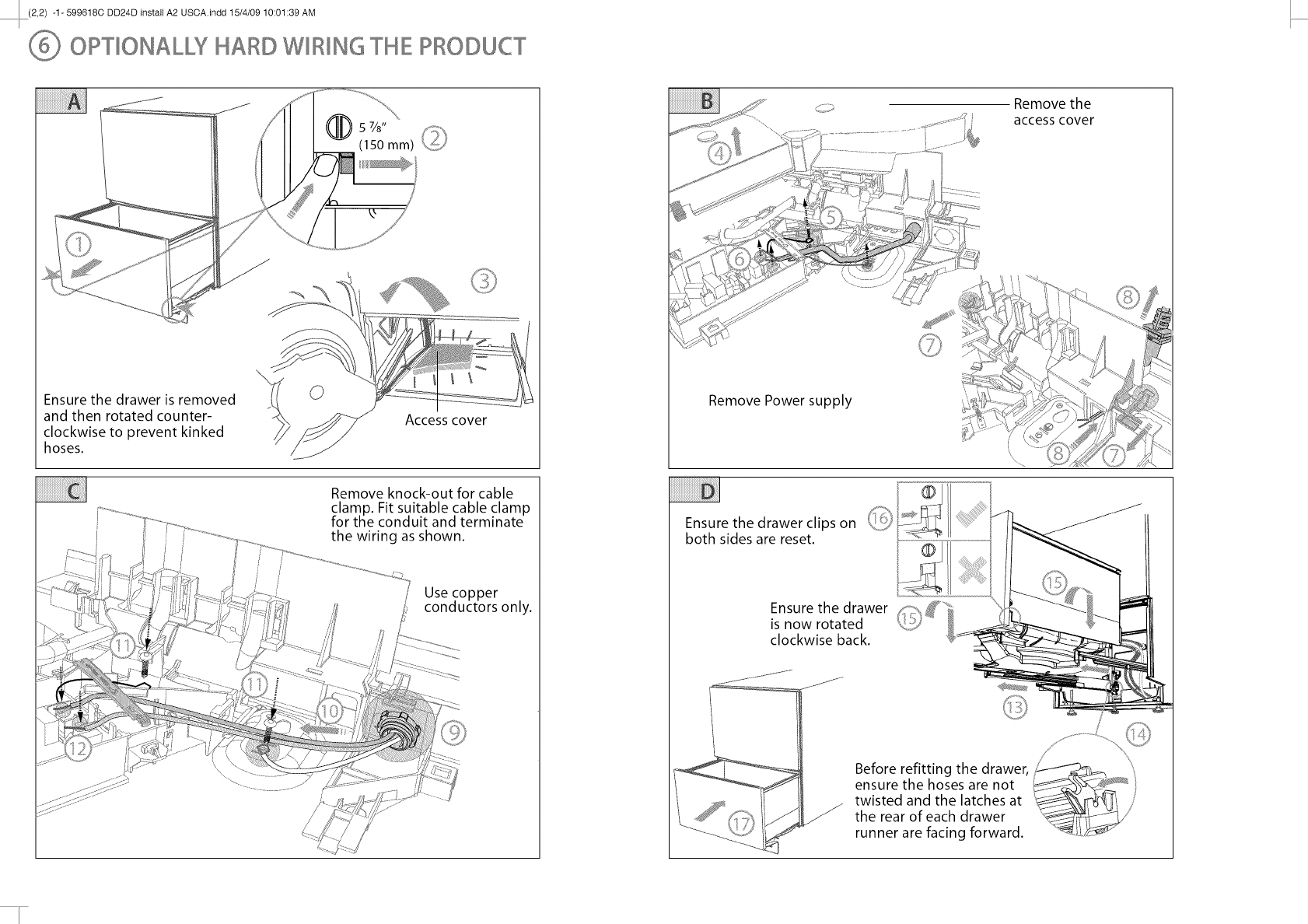
OPTIONALW HARD WIRING THE PRODUCT
Ensure the drawer is removed
and then rotated counter-
clockwise to prevent kinked
hoses.
Access cover
Remove knock-out for cable
clamp. Fit suitable cable clamp
for the conduit and terminate
the wiring as shown.
Use copper
conductors only.
Remove the
access cover
Remove Power supply
Ensure the drawer clips on c,/...._.,_
both sides are reset.
Ensure the drawer
is now rotated
clockwise back.
©
Before refitting the drawer,
ensure the hoses are not
twisted and the latches at
the rear of each drawer
runner are facing forward.
(1,1) -2- 599618C DD24D install A2 USCA.indd 15/4/09 10:02:23 AM
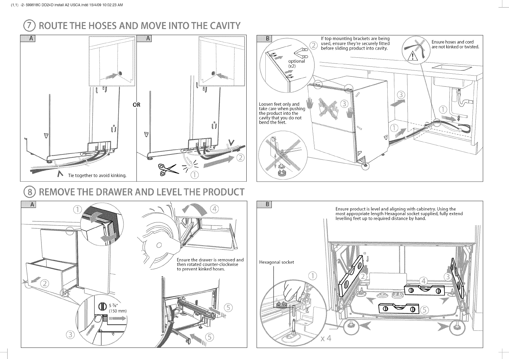
ROUTETHE HOSESAND MOVE _NTOTHE CAVITY
OR
REMOVETHE DRAWERAND LEVELTHE PRODUCT
Ensure the drawer is removed and
then rotated counter-clockwise
to prevent kinked hoses.
optional
(x2)
If top mounting brackets are being
used, ensure they're securely fitted
before sliding product into cavity.
Ensure hoses and cord
are not kinked or twisted.
Loosen feet only and _2
take care when pushing _q_'
the product into the /
cavity that you do not
bendthe feet.
Ensure product is level and aligning with cabinetry. Using the
most appropriate length Hexagonal socket supplied, fully extend
levelling feet up to required distance by hand.
Hexagonal socket
X4
I (1,2)-2-599618CDD24DinstallA2USCA.indd15/4/0910:02:23AM
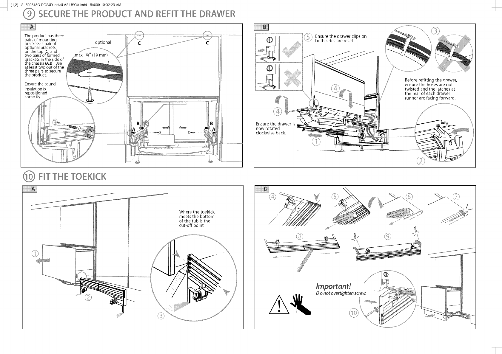
SECURE THE PRODUCT AND REFIT THE DRAWER
The product has three
pairs of mountinq
brackets: a pair of
optional brackets
on the top (C) and
two pairs of formed
brackets in the side of
the chassis (A,B). Use
at least two out of the
three pairs to secure
the product.
Ensure the sound
insulation is
repositioned
correctly.
optional
3A" (19 mm)
C
Ensurethe drawer is
now rotated
clockwise back.
Ensure the drawer clips on
D/
........,," both sides are reset.
Before refitting the drawer,
ensure the hoses are not
twisted and the latches at
the rear of each drawer
runner are facing forward.
_} F_TTHE TOEK_CK
Where the toekick
meets the bottom
of the tub is the
cut-off point
lmportand
D o not overtighten screw.
L(2,1) -2- 599618C DD24D install A2 USCA.indd 15/4/09 10:02:23 AM
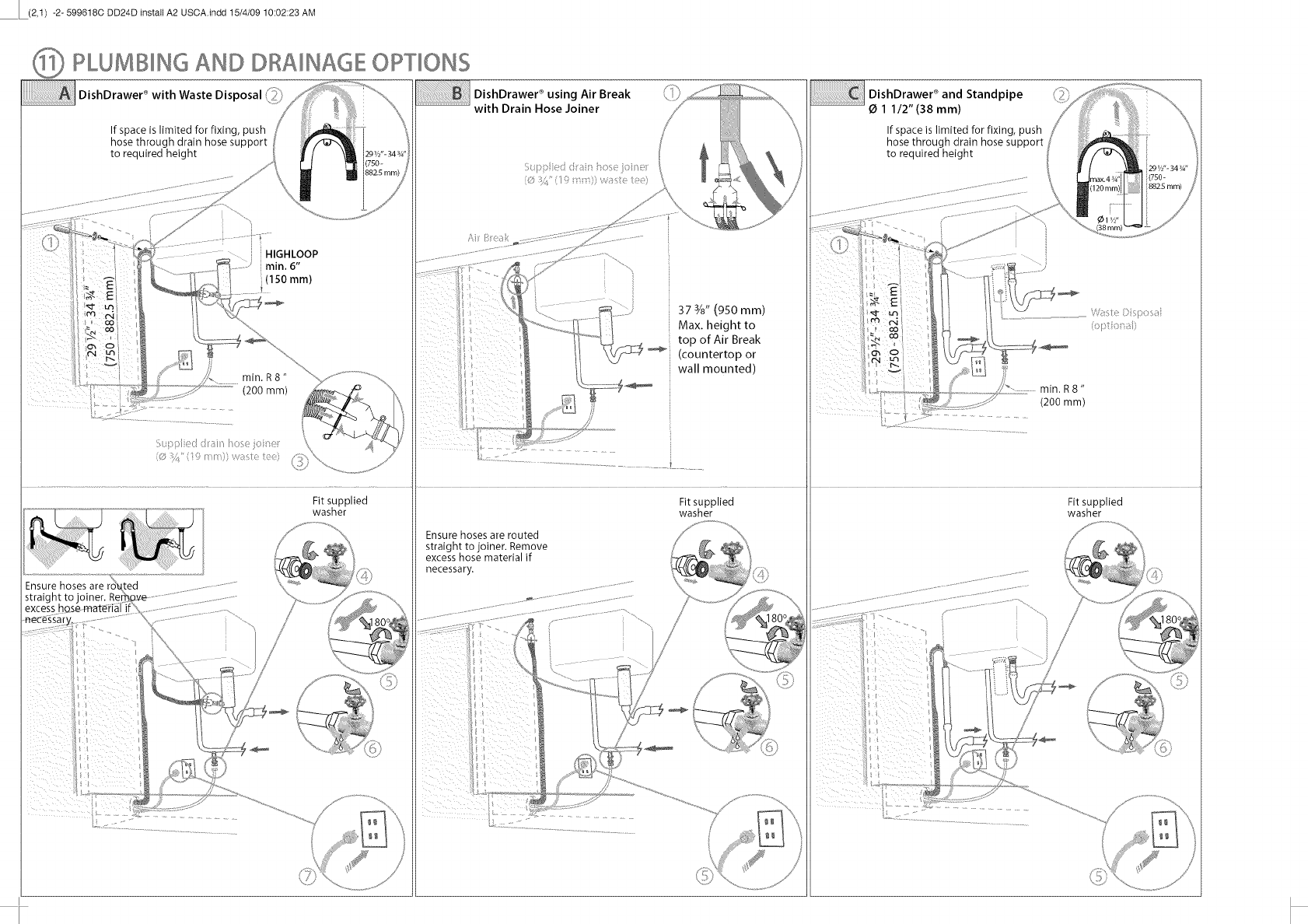
PLUMBING AND DRAINAGE OPTIONS
DishDrawer ®with Waste Disposal (_;il}
If space is limited for fixing, push
hose through drain hose support
to required height
HIGHLOOP
min. 6"
(150 ram)
!
min. R8"
(200 mm)
Ensure hoses
Fit supplied
washer
DishDrawer ®using Air Break
with Drain Hose Joiner
Ensure hoses are routed
straight to joiner. Remove
excess hose material if
necessary.
37 3/8"(950 mm)
Max. height to
top of Air Break
_] (countertop or
wall mounted)
Fit supplied
washer
DishDrawer ® and Standpipe
O 1 1/2"(38 mm)
If space is limited for fixing, push
hose through drain hose support
to required height
(200 mm)
Fit supplied
washer
/
t
L(2,2) -2- 599618C DD24D install A2 USCA.indd 15/4/09 10:02:23 AM
I
F NAL CHECKLIST
[] Check all parts are installed.
[] Ensure product is level, securely fastened to the cabinetry and opens and closes
freely. The DishDrawer ® must be free to fully close with no resistance from the
cabinetry.
[] Ensure inlet hose to water supply has rubber washer fitted and is tightened a
further half turn after seal contact.
[] Ensure any knockouts or plugs in drain connection have been drilled out and
drain connection has been made.
[] The drain hose joiner must not support the weight of excess hoses. Keep hoses
as fully extended as possible to prevent sagging. Any excess length of hose
should be kept on the dishwasher side of the high loop.
[] If using Plumbing and Drainage OPTION A, ensure the Highloop is a minimum
6"(150 mm) higher than the drain hose joiner.
[] Turn on the power and water supply. Then press the Power (©) button to turn
the DishDrawer ®on.The DishDrawer ® should beep and Wash Programme lights
light up.
[] Check the spray arm is in place and free to rotate.
[] Add three cups of water into the DishDrawer ®.On the Wash Programme
Selector Panel press Rinse and close the drawer(s). Start the programme by
pressing the Start/Pause (_H) button.
[] After the Rinse programme has finished, ensure machine has run and drained
correctly.
[] Check water supply and drainage connection for leakage.
Repeat for each drawer.
TROUBLESHOOTING
o Excessive water remaining above the filter plate, after the rinse cycle
Check for kinked drain hoses or blocked waste connection, high loop not
properly installed or drain hoses not routed correctly.
o No water suppJy (® shows on display-models with LCD only)
Check water is connected, turned on and the spray arm(s) are correctly fitted
and free to rotate.
o No lights come on when the drawer is opened
Ensure power is connected and is switched on. Check if Auto Power option is
on.
o Water around water suppJy and drainage connections
Check connections, existing plumbing and hoses for leaks. Check washer and
hose clamps are correctly fitted.
o If product is tipping
Ensure the product is secured to the cabinetry.
o If front panels are misaligned
Check and relevel product. Check the cabinetry is square.
o Drawer(s) don't dose properly
Ensure nothing is obstructing the drawer(s) from closing properly eg sound
insulation, hoses or drawer latches.
o If a problem occurs, consult the Troubleshooting section of the User Guide.
o If after checking these points you still need assistance, please refer to the
Service & Warranty book for warranty details and your nearest Authorized
Service Centre, or contact us through our website, www.fisherpaykel.com.
www.fisherpaykel.com www.fisherpaykel.ca 599618C US CA 04.09
