FLIR Systems DM93 Digital Multimeter User Manual L155 009696 G01 PG1 out
FLIR Systems AB Digital Multimeter L155 009696 G01 PG1 out
UserManual.wiki
>
FLIR Systems
>
DM93 User Manual
Manual
Navigation menu
Upload a User Manual
Namespaces
Wiki Guide
HTML
PDF
Info
Views
User Manual
Discussion / Help
Navigation


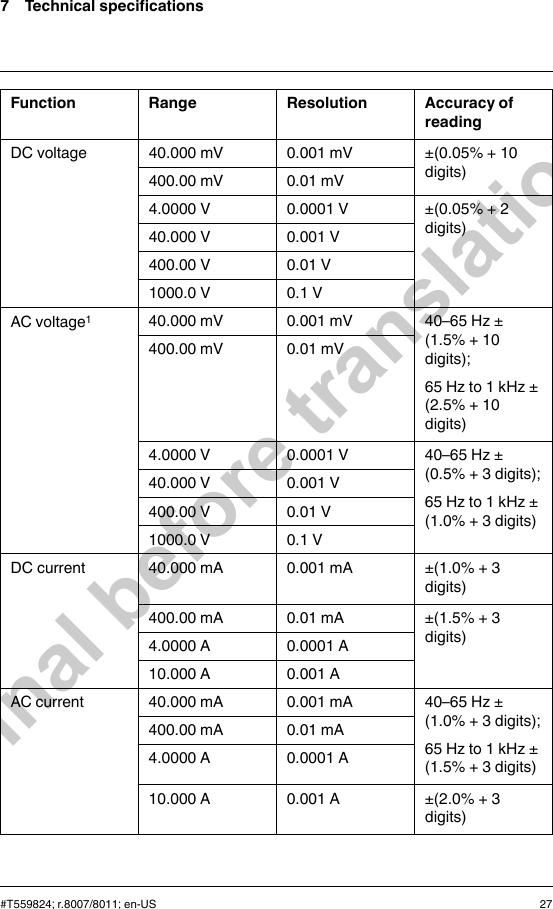

![DM93 Errata-en-US_A (insert to FLIR publication no. T559824 revision AC) FLIR DM93 - USER MANUAL ERRATA Correction No. 1 The term “For indoor use only; up to 2000m (7000’)” replaces the term “All weather housing” on page 6, Section 3.1 Key Features. Correction No. 2 The ACV specification below replaces the specifications on page 28 in Table 7.1 Voltage: Mode Range Accuracy 40 to 70 Hz 70 to 1k Hz 1k to 5k Hz 5k to 20k Hz[1] AC 40.00mV 0.5% +2d 1.0% + 4d 2.0% + 4d Unspecified 400.0mV 0.5% +2d 1.0% + 4d 2.0% + 4d 2.0% + 20d 4.000V 40.00V 400.0V 0.5% +2d 1.0% + 4d 2.0% + 4d[2] Unspecified 1000V 0.5% +2d 1.0% + 4d Unspecified Unspecified [1] Below 10% of range, add 10d to accuracy [2] Frequency range 1k to 2k Hz Addition This device complies with part 15 of the FCC Rules. Operation is subject to the following two conditions: 1. This device may not cause harmful interference. 2. This device must accept any interference received, including interference that may cause undesired operation. This equipment has been tested and found to comply with the limits for a Class B digital device, pursuant to part 15 of the FCC Rules. These limits are designed to provide reasonable protection against harmful interference in a residential installation. This equipment generates, uses, and can radiate radio frequency energy and, if not installed and used in accordance with the instructions, may cause harmful interference to radio communications. However, there is no guarantee that interference will not occur in a particular installation. If this equipment does cause harmful interference to radio or television reception, which can be determined by turning the equipment off and on, the user is encouraged to try to correct the interference by one or more of the following measures: Reorient or relocate the receiving antenna. Increase the separation between the equipment and receiver. Connect the equipment into an outlet on a circuit different from that to which the receiver is connected. Consult the dealer or an experienced radio/TV technician for help. Warning: Changes or modifications not expressly approved by the party responsible for compliance could void the user's authority to operate the equipment. Copyright © 2013 FLIR Systems, Inc. All rights reserved worldwide. Names and marks appearing herein are either registered trademarks or trademarks of FLIR Systems and/or its subsidiaries.](https://usermanual.wiki/FLIR-Systems/DM93/User-Guide-2083251-Page-41.png)