FLIR Systems DM93 Digital Multimeter User Manual L155 009696 G01 PG1 out
FLIR Systems AB Digital Multimeter L155 009696 G01 PG1 out
Manual
User’s manual
Flir DM93
Digital multimeter
Final before translation
Final before translation

User’s manual
Flir DM93
#T559824; r.8007/8011; en-US
Final before translation
Final before translation

Table of contents
1 Disclaimers..............................................................1
1.1 Copyright....................................................... 1
1.2 Quality assurance . . . . . . . . . . . . . . . .. . . . . . .. . . . . . .. . . . . . .. . . .. . . . 1
1.3 Documentation updates . . . . . . . . . . . . . . . . .. . . . . . .. . . . . . .. . . . . . .. 1
1.4 Disposal of electronic waste. . . . . . . . . . . . .. . . . . . .. . . . . . .. . . . . . .. 1
2 Safety information...................................................... 2
3 Introduction .............................................................6
3.1 Key features.................................................... 6
4 Description..............................................................7
4.1 Meter description . . . . . . . . . . . . . . . . . . . . . . . .. . . . . . . . . . . . . . . . . . . . . . 7
4.2 Function switch . . . . . . . . . . . . . . . . . . . . . .. . . . . . . . . . . . . . . . . . . . . . . . . . 8
4.3 Function buttons . . . . . . . . . . . . . . . . . . . . .. . . . . . .. . . . . . . . . . . . . . . . . . . 9
4.4 Display description . . . . . . . . . . .. . . . . . . . . . . . . . . . . . . . . . . . . . . . . . . .10
4.5 Display icons and indicators . . . . . . . . . . . . . . .. . . . . . . . . . . . . . . . . .10
5 Operation...............................................................13
5.1 Powering the meter . . . . . . . . . . . . . . .. . . . . . . . . . . . . . . . . . . . . . . . . . . .13
5.2 Auto/Manual select mode . . . . . . . . . . . . . . . . . . . . . . . . . . . . .. . . . . . . 13
5.3 Auto/Manual range mode . . . . . . . . . . . . . . .. . . . . . . . . . . . . . . . . . . . .14
5.4 Voltage measurements . . . . . . . . . . . . . . . . . .. . . . . . . . . . . . . . . . . . . . .14
5.5 Resistance measurements . . . . . . . . . . . . . . . . . . . . . . . . . . . . . . . .. . . 15
5.6 Continuity test.................................................15
5.7 Diode test.....................................................16
5.8 Capacitance measurements . . . . . . . . . . . .. . . . . . .. . . . . . . . . . . . . . 16
5.9 Type K temperature measurements. . . . . . . . . . . . . . . .. . . . . . .. . .17
5.10 Current measurements . . . . . . . . . . . . . . . . . . . . . . . . . . . . . . . . . . . .. . . 17
5.11 Extended functionality . . . . . . . . . . . . . . . . . . . . . . . . . . . . . .. . . . . . . . . . 18
5.12 Hold mode ....................................................22
5.13 Locked mode .................................................22
5.14 Streaming measurement data using Bluetooth . . . . . . . . . . . . . . 22
6 Maintenance............................................................24
6.1 Cleaning and storage. . . . . . . . . . . . . . . .. . . . . . . . . . . . . . . . . . . . . . . . .24
6.2 Battery replacement . . . . . . . . . . . . . . . . . . . . . . . .. . . . . . . . . . . . . . . . . .24
6.3 Fuse replacement . . . . . . . . . . . . . . . . . . . . . . . . . .. . . . . . . . . . . . . . . . . .24
6.4 Disposal of electronic waste. . . . . . . . . . . . .. . . . . . . . . . . . . . . . . . . . .24
#T559824; r.8007/8011; en-US v
Final before translation

Table of contents
7 Technical specifications . . . . . . . . . . . . . .. . . . . . .. . . . . . . . . . . . . . . . . . . . . . . . .25
7.1 General specifications . . . . . . . . . . . . . . .. . . . . . . . . . . . . . . . . . . . . . . . .25
7.2 Electrical range specifications . . . . . . . . . . . . .. . . . . . . . . . . . . . . . . .26
7.3 Thermal measurement range specifications. . . . . . . . . . . . . . . . .29
7.4 Input specifications . . . . . . . . . . . . . . . . . . . . . . . . .. . . . . . . . . . . . . . . . . .29
8 Flir Global Limited Lifetime Warranty . . . . . .. . . . . . . . . . . . . . . . . . . . . . . . .30
#T559824; r.8007/8011; en-US vi
Final before translation
1 Disclaimers
1.1 Copyright
© 2013, Flir Systems, Inc. All rights reserved worldwide.
No parts of the software including source code may be re-
produced, transmitted, transcribed or translated into any
language or computer language in any form or by any
means, electronic, magnetic, optical, manual or otherwise,
without the prior written permission of Flir Systems.
The documentation must not, in whole or part, be copied,
photocopied, reproduced, translated or transmitted to any
electronic medium or machine readable form without prior
consent, in writing, from Flir Systems.
Names and marks appearing on the products herein are
either registered trademarks or trademarks of Flir Sys-
tems and/or its subsidiaries. All other trademarks, trade
names or company names referenced herein are used for
identification only and are the property of their respective
owners.
1.2 Quality assurance
The Quality Management System under which these
products are developed and manufactured has been certi-
fied in accordance with the ISO 9001 standard.
Flir Systems is committed to a policy of continuous devel-
opment; therefore we reserve the right to make changes
and improvements on any of the products without prior
notice.
1.3 Documentation updates
Our manuals are updated several times per year, and we
also issue product-critical notifications of changes on a
regular basis.
To access the latest manuals and notifications, go to the
Download tab at:
http://support.flir.com
It only takes a few minutes to register online. In the down-
load area you will also find the latest releases of manuals
for our other products, as well as manuals for our historical
and obsolete products.
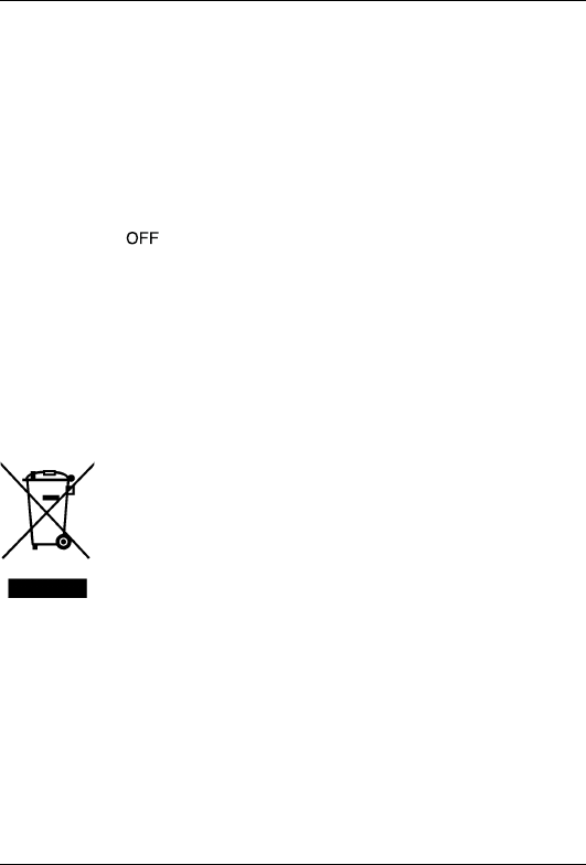
1.4 Disposal of electronic waste
As with most electronic products, this equipment must be
disposed of in an environmentally friendly way, and in ac-
cordance with existing regulations for electronic waste.
Please contact your Flir Systems representative for more
details.
#T559824; r.8007/8011; en-US 1
Final before translation
2 Safety information
Note
Before operating the device, you must read, understand, and follow all in-
structions, dangers, warnings, cautions, and notes.
Note
Flir Systems reserves the right to discontinue models, parts or accessories,
and other items, or to change specifications at any time without prior notice.
Note
Remove the batteries if the device is not used for an extended period of time.
WARNING
Do not operate the device if you do not have the correct knowledge. Formal
qualifications and/or national legislation for the electrical inspections can ap-
ply. Incorrect operation of the device can cause damage, shock, injury or
death to persons.
WARNING
Do not start the measuring procedure before you have set the function switch
to the correct position. This can cause damage to the instrument and can
cause injury to persons.
WARNING
Do not change to current or resistance when you measure the voltage. This
can cause damage to the instrument and can cause injury to persons.
#T559824; r.8007/8011; en-US 2
Final before translation
2 Safety information
WARNING
Do not measure the current on a circuit when the voltage increases to more
than 600 V. This can cause damage to the instrument and can cause injury to
persons.
WARNING
You must disconnect the test leads from the circuit that you did a test on be-
fore you change the range. If you do not do this, damage to the instrument
and injury to persons can occur.
WARNING
Do not replace the batteries or the fuses before you remove the test leads.
This can cause damage to the instrument and can cause injury to persons.
WARNING
Do not use the device if the test leads and/or the device show signs of dam-
age. Injury to persons can occur.
WARNING
Be careful when you do the measurements if the voltages are more than 25
VAC rms or 35 VDC. There is a risk of shock from these voltages. Injury to per-
sons can occur.
WARNING
Do not do diode, resistance or continuity tests before you have removed the
power from the capacitors and from a device during a test. Injury to persons
can occur.
#T559824; r.8007/8011; en-US 3
Final before translation
2 Safety information
WARNING
Do not use the device as a tool to identify live terminals. You must use the cor-
rect tools. Injury to persons can occur if you do not use the correct tools.
WARNING
Make sure that children cannot touch the device. The device contains danger-
ous objects and small parts that children can swallow. If a child swallows an
object or a part, speak with a physician immediately. Injury to persons can
occur.
WARNING
Do not let children play with the batteries and/or the packing material. These
can be dangerous for children if they use them as toys.
WARNING
Do not touch expired or damaged batteries without gloves. Injury to persons
can occur.
WARNING
Do not cause a short-circuit of the batteries. This can cause damage to the in-
strument and can cause injury to persons.
WARNING
Do not put the batteries into a fire. Injury to persons can occur.
CAUTION
Do not use the device for a procedure that it is not made for. This can cause
damage to the protection.
#T559824; r.8007/8011; en-US 4
Final before translation

2 Safety information
This symbol, adjacent to another symbol or terminal, indicates that
the user must refer to the manual for further information.
This symbol, adjacent to a terminal, indicates that, under normal
use, hazardous voltages may be present.
Double insulation.
#T559824; r.8007/8011; en-US 5
Final before translation

3 Introduction
Thank you for choosing a Flir DM93 digital multimeter.
This device is shipped fully tested and calibrated and, with proper use, will pro-
vide years of reliable service.
3.1 Key features
• 40 000/4000-count extra-large digital display.
• 43-segment bar graph.
• Auto backlit, dual display.
• Auto AC, DC, and AC+DC in voltage and current mode with frequency
indication.
• Auto selection for resistance, diode polarity, or continuity.
• On-screen menu selection.
• Navigator key drive.
• High-frequency rejection (HFR).
• 0.03% DCV accuracy.
• AC+DC true RMS indication.
• 0.5 ms peak hold.
• Auto hold.
• Store/recall memories.
• dBm/dB measurement.
• 20 000-record data logging capacity.
• All-weather housing.
• Optical USB interface with software included.
• Magnetic hanging kit.
• CAT. IV 600 V/CAT. III 1000 V standard.
#T559824; r.8007/8011; en-US 6
Final before translation
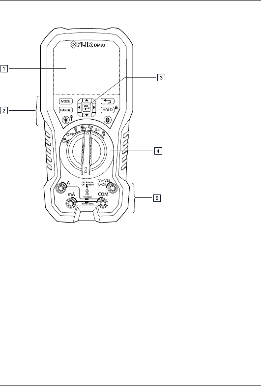
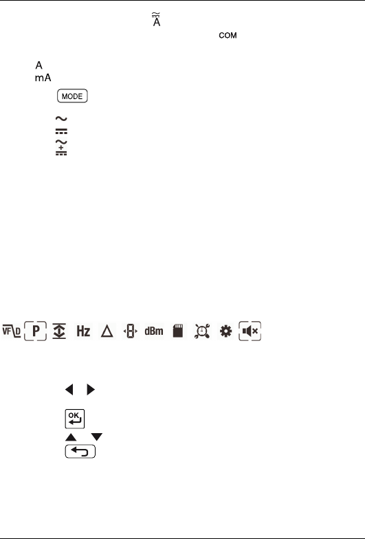
4 Description
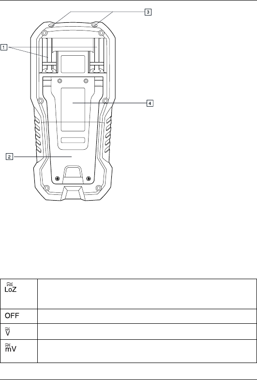
Figure 4.2 Rear view
1. Probe clips.
2. Tilt stand.
3. Work light.
4. Battery compartment cover.
4.2 Function switch
The meter can measure voltage through the probe inputs. A low-
impedance load is placed across the inputs to stabilize the
measurement.
The meter is in full power-saving mode.
The meter can measure high voltage (V) through the probe inputs.
The meter can measure low voltage (mV) through the probe
inputs.
#T559824; r.8007/8011; en-US 8
Final before translation
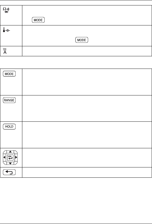
4 Description
The meter can measure resistance, continuity, or diode polarity
through the probe inputs. The type of measurement is selected by
the button.
The meter can measure capacitance through the probe inputs or
temperature through a thermocouple adapter. The type of meas-
urement is selected by the button.
The meter can measure current through the probe inputs.
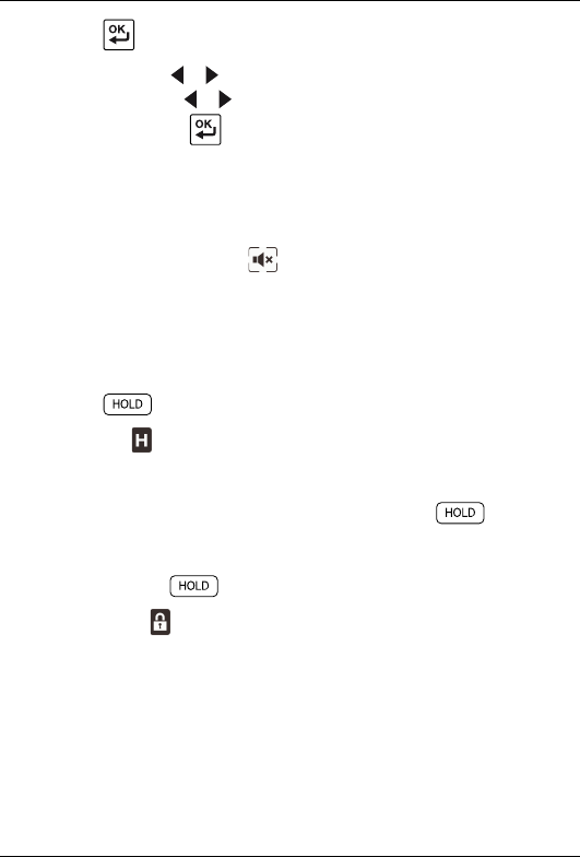
4.3 Function buttons
• Use the button to select Auto select or Manual select mode,
see section 5.2 Auto/Manual select mode, page 13.
• In Manual select mode, press the button to change the operat-
ing mode.
• Use the button to select Auto range or Manual range mode,
see section 5.3 Auto/Manual range mode, page 14.
• In Manual range mode, press the button to change the range
(scale).
• Press the button to toggle between Normal and Hold mode,
see section 5.12 Hold mode, page 22.
• Press and hold the button for 5 seconds to enable/disable
Locked mode, see section 5.13 Locked mode, page 22.
Use the selector pad to enable extended functionality modes and
to navigate in mode options.
Press the button to exit an extended functionality mode.
#T559824; r.8007/8011; en-US 9
Final before translation
4 Description
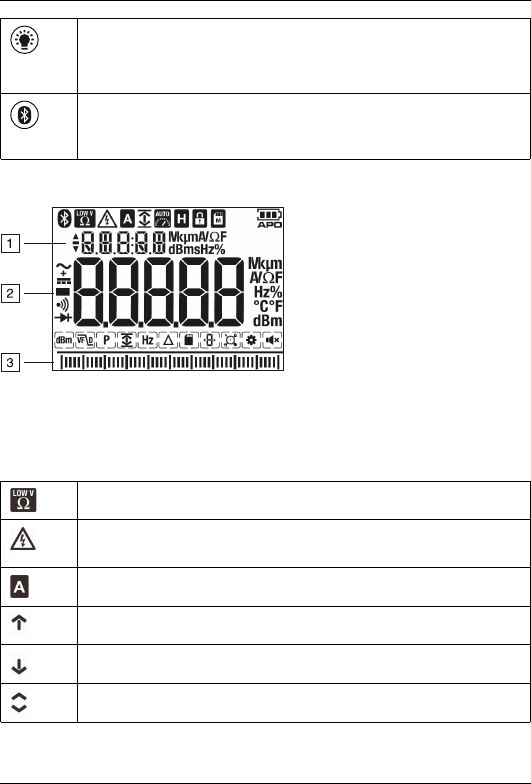
• Press the button to enable/disable the display backlight.
• Press and hold the button for 2 seconds to enable/disable the
work light.
Press the button to enable/disable MeterLink (Bluetooth) commu-
nication, see section 5.14 Streaming measurement data using
Bluetooth, page 22.
4.4 Display description
1. Secondary display.
2. Main display.
3. Bar graph (matches the reading on the main display).
4.5 Display icons and indicators
Indicates that the meter is measuring stabilized voltage.
Indicates that the measured voltage is greater than 40 V (AC or
DC).
Indicates that the Auto select mode is active.
Indicates that the meter is displaying maximum reading values.
Indicates that the meter is displaying minimum reading values.
Indicates that the meter is displaying the average reading.
#T559824; r.8007/8011; en-US 10
Final before translation
4 Description
Indicates that the meter is displaying peak maximum values.
Indicates that the meter is displaying peak minimum values.
Indicates that the meter is in Auto range mode.
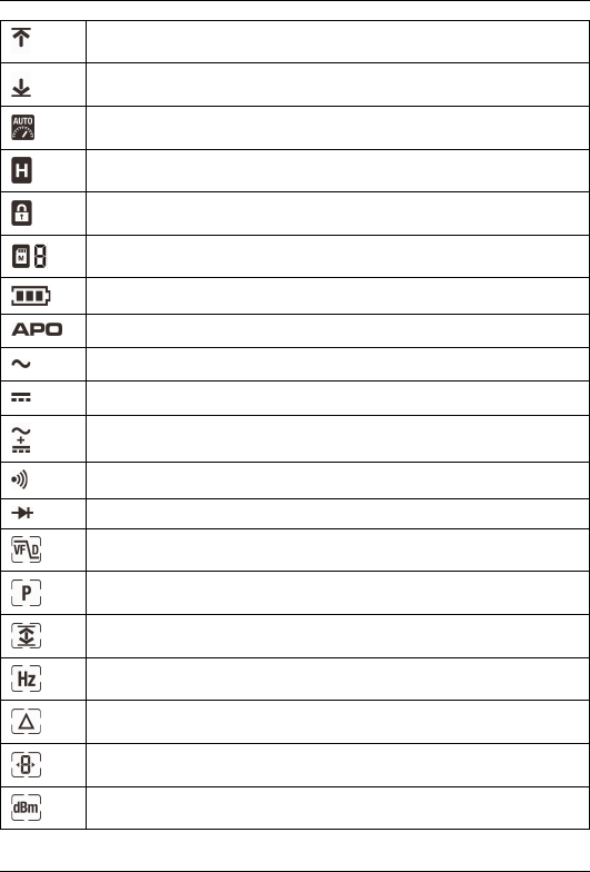
Indicates that the meter is in Hold mode.
Indicates that the meter is in Locked mode.
Indicates the active memory location (1–99).
Indicates the battery voltage status.
Indicates that the auto power off function is enabled.
Indicates that the meter is measuring AC current or voltage.
Indicates that the meter is measuring DC current or voltage.
Indicates that the meter is measuring AC+DC current or voltage.
Indicates that the continuity function is active.
Indicates that the diode test function is active.
LPF mode icon.
Peak mode icon.
Min/Max/Avg mode icon.
Frequency mode icon.
Relative mode icon.
Readout mode icon.
dBm mode icon.
#T559824; r.8007/8011; en-US 11
Final before translation

4 Description
Data logging mode icon.
Sampling mode icon.
Setup mode icon.
Silent mode icon.
4.5.1 Out-of-range warning
If the input is over/under the full-scale range in Manual range mode, or if the sig-
nal has exceeded the maximum/minimum input in Auto range mode, OL is
displayed.
#T559824; r.8007/8011; en-US 12
Final before translation
5 Operation
Note
Before operating the device, you must read, understand, and follow all in-
structions, dangers, warnings, cautions, and notes.
Note
When the meter is not in use, the function switch should be set to the
position.
Note
When connecting the probe leads to the device under test, connect the nega-
tive lead before connecting the positive lead. When removing the probe
leads, remove the positive lead before removing the negative lead.
5.1 Powering the meter
1. Set the function switch to any position to switch on the meter.
2. If the battery indicator shows that the battery voltage is low or if the me-
ter does not power on, replace the battery. See section 6.2 Battery replace-
ment, page 24.
5.1.1 Auto power off
The meter enters sleep mode after a programmable number of minutes of inactiv-
ity, see section 5.11.10 Setup mode, page 21.
The meter beeps three times 20 seconds before powering off. Press any button
or turn the function switch to prevent the meter from powering off. The auto power
off time-out is then reset.
5.2 Auto/Manual select mode
In Auto select mode, the meter attempts to automatically select the proper oper-
ating mode based on the input signal:
• If the function switch is set to the , , , or position, the meter at-
tempts to determine if the AC, DC, or AC+DC mode should be used.
#T559824; r.8007/8011; en-US 13
Final before translation
5 Operation
• If the function switch is set to the position, the meter attempts to deter-
mine if the device under test is a resistor, capacitor, or diode.
Auto select mode is the default mode of operation. When a new function is se-
lected with the function switch, the starting mode is Auto select and the indi-
cator is displayed.
To enter Manual select mode, press the button. To manually select the op-
erating mode, press the button repeatedly.
To enter Auto select mode, press and hold the button until the indicator
is displayed.
5.3 Auto/Manual range mode
In Auto range mode, the meter automatically selects the most appropriate meas-
urement scale. In Manual range mode, the desired range (scale) is set manually.
• To enter Manual range mode, press the button. To change the range,
press the button repeatedly until the desired range is displayed.
• To enter Auto range mode, press and hold the button until the indi-
cator is displayed.
5.4 Voltage measurements
1. Set the function switch to one of the following positions:
•for high voltage measurements.
•for low voltage measurements.
•for stabilized voltage measurements. The indicator is displayed.
2. Insert the black probe lead into the negative terminal and the red probe
lead into the positive terminal.
3. Use the button to select AC, DC, or AC+DC voltage measurement.
• The indicator will be displayed for AC measurements.
• The indicator will be displayed for DC measurements.
• The indicator will bedisplayed for AC+DC measurements.
#T559824; r.8007/8011; en-US 14
Final before translation
5 Operation
4. For stabilized voltage measurements, place a low-impedance load across
the probe inputs.
5. Connect the probe leads in parallel to the part under test.
6. Read the voltage value on the display.
5.5 Resistance measurements
WARNING
Do not do diode, resistance or continuity tests before you have removed the
power from the capacitors and from a device during a test. Injury to persons
can occur.
1. Set the function switch to the position.
2. Ensure that the meter is set to resistance measurement. The Ω unit will be
displayed.
If the or indicator is displayed, press the button repeatedly until
the Ω unit is displayed.
3. Insert the black probe lead into the negative terminal and the red probe
lead into the positive terminal.
4. Touch the tips of the probe across the circuit or component under test.
5. Read the resistance value on the display.
5.6 Continuity test
WARNING
Do not do diode, resistance or continuity tests before you have removed the
power from the capacitors and from a device during a test. Injury to persons
can occur.
1. Set the function switch to the position.
2. Use the button to select continuity measurement. The indicator will
be displayed.
3. Insert the black probe lead into the negative terminal and the red probe
lead into the positive terminal.
4. Touch the tips of the probe across the circuit or component under test.
#T559824; r.8007/8011; en-US 15
Final before translation
5 Operation
5. If the resistance is 25 ± 5 Ω(nominal) or less, the meter beeps.
5.7 Diode test
WARNING
Do not do diode, resistance or continuity tests before you have removed the
power from the capacitors and from a device during a test. Injury to persons
can occur.
1. Set the function switch to the position.
2. Use the button to select the diode test function. The indicator will
be displayed.
3. Insert the black probe lead into the negative terminal and the red probe
lead into the positive terminal.
4. Touch the tips of the probe across the diode or semiconductor junction under
test. Make a note of the value on the display.
5. Reverse the polarity of the probes, by interchanging the probe test locations.
6. Touch the tips of the probe across the diode or semiconductor junction under
test. Make a note of the new value on the display.
7. The diode or semiconductor junction can be evaluated as follows:
• If one of the readings displays a value (typically 0.400 V or 0.900 V) and
the other reading displays OL, the component is good.
• If both readings display OL, the component is open.
• If both readings are very small or 0, the component is shorted.
5.8 Capacitance measurements
WARNING
Do not do diode, resistance or continuity tests before you have removed the
power from the capacitors and from a device during a test. Injury to persons
can occur.
1. Set the function switch to the position.
2. Use the button to select capacitance measurement. The F unit will be
displayed.
#T559824; r.8007/8011; en-US 16
Final before translation
5 Operation
3. Insert the black probe lead into the negative terminal and the red probe
lead into the positive terminal.
4. Touch the tips of the probe across the part under test.
5. Read the capacitance value on the display.
Note
For very large capacitance values, it may take several minutes for the
measurement to settle and the final reading to stabilize.
5.9 Type K temperature measurements
1. Set the function switch to the position.
2. Use the button to select temperature measurement. The °F or °C unit
will be displayed.
3. While observing the polarity, insert the thermocouple adapter into the nega-
tive terminal and the positive terminal.
4. Touch the tip of the thermocouple to the part under test. Keep the thermo-
couple tip on the part until the reading on the display stabilizes.
5. Read the temperature value on the display.
6. To avoid electrical shock, disconnect the thermocouple adapter before turn-
ing the function switch to another position.
5.10 Current measurements
Current is measured by disconnecting the part under test and connecting the
probe leads in series with the part, see Figure 5.1.
Figure 5.1 Disconnected component
#T559824; r.8007/8011; en-US 17
Final before translation
5 Operation
1. Set the function switch to the position.
2. Insert the black probe lead into the negative terminal and the red probe
lead into one of the following positive terminals:
•for high current measurements.
•for low current measurements.
3. Use the button to select AC, DC, or AC+DC voltage measurement.
• The indicator will be displayed for AC measurements.
• The indicator will be displayed for DC measurements.
• The indicator will be displayed for AC+DC measurements.
4. Connect the probe leads in series with the part in accordance with Figure
5.1.
5. Read the current value on the display.
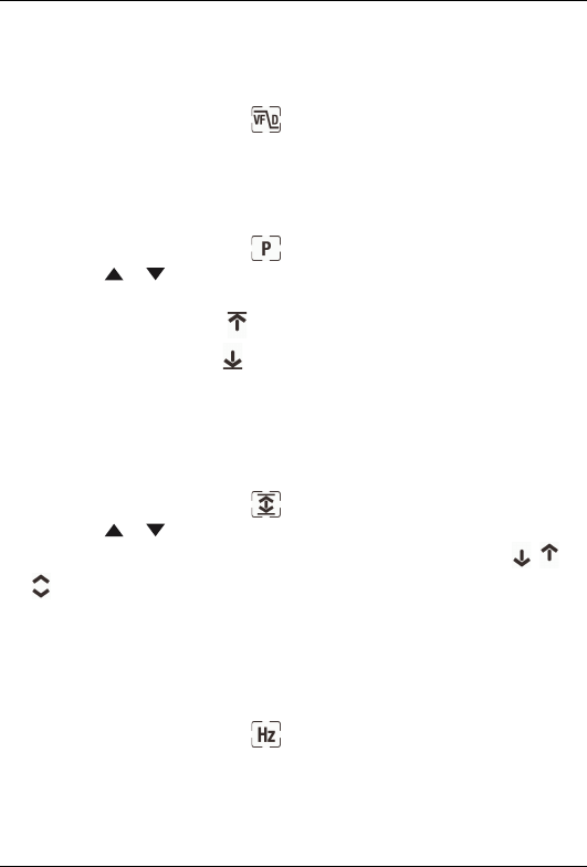
5.11 Extended functionality
In addition to the basic measurements, the meter can be set to different modes
for extended functionality.
5.11.1 Selecting the mode
The mode icons applicable for the selected measurement type are displayed in
the lower part of the display. When a mode is enabled, the icon is framed.
Figure 5.2 Mode icons (AC voltage measurements): Peak mode and Silent
mode are enabled
1. Press the or button to navigate to the desired mode icon. The currently
selected icon will flash.
2. Press the button to enable the selected (flashing) mode.
3. Press the or button to step through the mode options.
4. Press the button to disable the selected (flashing) mode.
#T559824; r.8007/8011; en-US 18
Final before translation
5 Operation
5.11.2 LPF mode (ACV only)
In LPF mode, high-frequency noise is eliminated from the voltage measurement
by a low-pass filter (LPF). LPF mode is available when measuring AC voltage.
1. Use the selector pad to select and enable LPF mode.
5.11.3 Peak mode (ACV and ACA only)
In Peak mode, the meter captures and displays the positive and negative peak
values, and updates only when a higher/lower value is registered.
1. Use the selector pad to select and enable Peak mode.
2. Press the or button to toggle between the display of Peak Max and
Peak Min.
• In Peak Max mode, the indicator is displayed.
• In Peak Min mode, the indicator is displayed.
5.11.4 Min/Max/Avg mode
In Min/Max/Avg mode, the meter captures and displays the minimum or maxi-
mum values and updates only when a higher/lower value is registered. The meter
can also calculate the average of the minimum and maximum values.
1. Use the selector pad to select and enable the Min/Max/Avg mode.
2. Press the or button to cycle through the minimum, maximum, and
average reading displays. The corresponding icons are displayed: , , or
.
5.11.5 Frequency mode (ACV and ACA only)
In Frequency mode, the frequency is displayed in the main display and the period
or duty cycle is displayed in the secondary display. Frequency mode is available
when measuring AC voltage or current.
1. Use the selector pad to select and enable Frequency mode.
#T559824; r.8007/8011; en-US 19
Final before translation
5 Operation
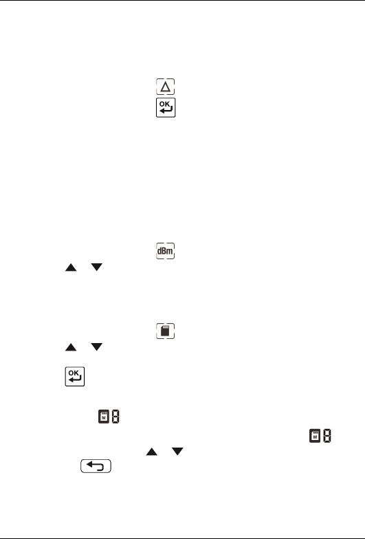
5.11.6 Relative mode
In Relative mode, the difference (Δ) between the current reading and a stored
reference value is displayed in the main display. The reference value is displayed
in the secondary display.
1. Use the selector pad to select and enable Relative mode. (The refer-
ence value is stored when the button is pressed.)
5.11.7 dBm mode (ACV only)
The decibel (dB) is a logarithmic unit that expresses the magnitude of a physical
quantity relative to a specified or implied reference level. In dBm mode, the meter
displays AC voltage measurements in dB or dBm on the secondary display.
dB and dBm are defined as follows:
• dB = 20 log (VAC/1).
• dBm = 20 log (VAC/0.7746).
1. Use the selector pad to select and enable dBm mode.
2. Press the or button to toggle between the display of dB and dBm.
5.11.8 Data logging mode
The meter has 99 memory locations for the storage of measurement data.
1. Use the selector pad to select and enable Data logging mode.
2. Press the or button cycle through the mode options SAVE,LOAD, and
CLEAR shown on the secondary display.
3. Press the button to activate the displayed option:
•SAVE: The data on the main display is saved to the memory location
shown by the indicator in the upper part of the display.
•LOAD: The data stored in the memory location shown by the indica-
tor is displayed. Use the or button to change the memory location.
Press the button to exit the load function.
•CLEAR: The data in all memory locations is cleared.
#T559824; r.8007/8011; en-US 20
Final before translation
5 Operation
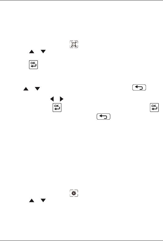
5.11.9 Sampling mode
In Sampling mode, the meter logs measurement data at the user-programmed
sampling rate. The logged data can be recalled at a later time for review. Up to
20 000 records can be logged into memory. The sampling rate can be set to a
value in the range 0.5 to 600 seconds.
1. Use the selector pad to select and enable Sampling mode.
2. Press the or button to cycle through the mode options VIEW,RATE,
SEND, and START shown on the secondary display.
3. Press the button to activate the displayed option:
•VIEW: The secondary display shows the current memory location. The
main display shows the data stored in the current memory location. Use
the or button to change memory location. Press the button
to exit the view function.
•RATE: Press the or button to change the sampling rate.
•START: Press the button to start the data sampling. Press the
button to pause the sampling. Press the button to stop the
sampling.
5.11.10 Setup mode
In Setup mode, you can define the settings for various meter options:
• Auto power off: The meter enters the sleep mode after a programmable num-
ber of minutes of inactivity. The auto power off timer can be set to 10 minutes
(factory default), 20 minutes, 30 minutes, or Off.
• Auto backlight off: The display backlight automatically turns on in a dark envi-
ronment. The backlight turns off after a programmable number of minutes of
inactivity. The auto backlight off timer can be set to a value in the range of 1 to
60 minutes (the factory default is 5 minutes).
1. Use the selector pad to select and enable Setup mode.
2. Press the or button to cycle through the mode options APO,LIGHT,
and RESET shown on the secondary display.
#T559824; r.8007/8011; en-US 21
Final before translation
5 Operation
3. Press the button to activate the displayed option:
•APO: Press the or button to change the auto power off time.
•LIGHT: Press the or button to change the auto backlight off time.
•RESET: Press the button to reset the settings to the factory default.
5.11.11 Silent mode
In Silent mode, the alert beeper is disabled. Silent mode does not affect the con-
tinuity beeper.
1. Use the selector pad to select and enable Silent mode.
5.12 Hold mode
In Hold mode, the secondary display freezes the last reading from the main dis-
play and continues to display this value. The current reading is displayed on the
main display.
1. Press the button to enter/exit Hold mode.
In Hold mode, the indicator is displayed.
5.13 Locked mode
In Locked mode, the meter ignores all button presses except . The auto
power off function, see section 5.1.1 Auto power off, page 13, is disabled in
Locked mode.
1. Press and hold the button for 3 seconds to enter/exit Locked mode.
In Locked mode, the indicator is displayed.
5.14 Streaming measurement data using Bluetooth
5.14.1 General
Some IR cameras from Flir Systems support Bluetooth communication, and to
those cameras you can stream measurement data from the meter. The data is
then merged into the result table in the IR image.
#T559824; r.8007/8011; en-US 22
Final before translation

5 Operation
Streaming measurement data is a convenient way to add important information
to an IR image. For example, when identifying an overheated cable connection,
you may want to know the current in that cable.
5.14.2 Procedure
1. Pair the IR camera with the instrument. Refer to the camera manual for infor-
mation on how to pair Bluetooth devices.
2. Turn on the camera.
3. Turn on the meter.
4. Press the on the meter to enable Bluetooth.
5. Choose the variable that you want to use (voltage, current, resistance, etc.).
Results from the meter will now automatically be displayed in the result table
in the top left corner of the IR camera screen.
#T559824; r.8007/8011; en-US 23
Final before translation
6 Maintenance
6.1 Cleaning and storage
Clean the meter with a damp cloth and mild detergent; do not use abrasives or
solvents.
If the meter is not to be used for an extended period, remove the batteries and
store them separately.
6.2 Battery replacement
1. To avoid electrical shock, disconnect the meter if connected to a circuit, re-
move the probe/thermocouple leads from the terminals, and set the function
switch to the position before attempting to replace the batteries.
2. Unscrew and remove the battery compartment cover.
3. Replace the six standard AAA batteries, observing correct polarity.
4. Secure the battery compartment cover.
6.3 Fuse replacement
The fuses are accessed via the battery compartment cover.
Only use recommended fuses, see section 7 Technical specifications, page 25.
6.4 Disposal of electronic waste
As with most electronic products, this equipment must be disposed of in an envi-
ronmentally friendly way, and in accordance with existing regulations for elec-
tronic waste.
Please contact your Flir Systems representative for more details.
#T559824; r.8007/8011; en-US 24
Final before translation

7 Technical specifications
7.1 General specifications
Display 40 000-count with bar
Controls • 6-position rotary function switch
• 4-way selector pad with center
OK button
• (6) dedicated function buttons:
mode, range, cancel, hold, Blue-
tooth, backlight
Backlight White LED
Work light White LED array
Measurement ranges See section 7.2 Electrical range
specifications, page 26
Basic accuracy 0.06%
Measurement rate 20 per second, nominal
Display rate 2 times per second
Input impedance >10 MΩV DC, > 3 MΩ V AC in Nor-
mal mode
< 10 kΩ in Low Impedance mode
AC voltage bandwidth 45 Hz to 1 kHz
Power supply 6 × AAA batteries (LR03)
Battery life 100 hours, using alkaline batteries,
with no backlight, Bluetooth, or work
light use
Auto power off (APO) After a programmable number of mi-
nutes of inactivity, with audible pre-
alert; reset when the function switch
or buttons are pressed. Disable func-
tion supported.
#T559824; r.8007/8011; en-US 25
Final before translation

7 Technical specifications
APO quiescent current 50 µA maximum
Measurement type True RMS, crest factor ≤ 3 at full
scale up to 500 V, decreasing linearly
to ≤ 1.5 at 1000 V
Over-current protection • mA, μA ranges; 0.5 A/1000 V ce-
ramic fast-blow fuse
• Ampere range; 10 A/1000 V ce-
ramic fast-blow fuse
Continuity test Visual and audible (85 dBA)
Other indications Low battery, over-range, memory
Internal memory 9 storage locations
Operating temperature –10 to 50°C (14 to 122°F)
Storage temperature –30 to 60°C (–14 to 140°F)
Operating humidity Maximum 90% up to 35°C (95°F),
decreasing linearly to 60% at (45°C)
113°F
Storage humidity 90% maximum
Dimensions 207 mm × 98 mm × 63 mm (8.15″ ×
3.9″ × 2.5″)
Weight 0.55 kg (1.22 lb), including batteries
Agency approvals FCC Class B, CE, UL/CSA, GSA, S-
JQA
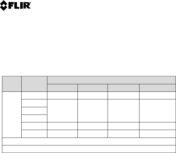
7.2 Electrical range specifications
Note
Accuracy is stated at 18–28°C (65–83°F) and less than 75% relative humidity.
#T559824; r.8007/8011; en-US 26
Final before translation

7 Technical specifications
Function Range Resolution Accuracy of
reading
DC voltage 40.000 mV 0.001 mV ±(0.05% + 10
digits)
400.00 mV 0.01 mV
4.0000 V 0.0001 V ±(0.05% + 2
digits)
40.000 V 0.001 V
400.00 V 0.01 V
1000.0 V 0.1 V
AC voltage140.000 mV 0.001 mV 40–65 Hz ±
(1.5% + 10
digits);
65 Hz to 1 kHz ±
(2.5% + 10
digits)
400.00 mV 0.01 mV
4.0000 V 0.0001 V 40–65 Hz ±
(0.5% + 3 digits);
65 Hz to 1 kHz ±
(1.0% + 3 digits)
40.000 V 0.001 V
400.00 V 0.01 V
1000.0 V 0.1 V
DC current 40.000 mA 0.001 mA ±(1.0% + 3
digits)
400.00 mA 0.01 mA ±(1.5% + 3
digits)
4.0000 A 0.0001 A
10.000 A 0.001 A
AC current 40.000 mA 0.001 mA 40–65 Hz ±
(1.0% + 3 digits);
65 Hz to 1 kHz ±
(1.5% + 3 digits)
400.00 mA 0.01 mA
4.0000 A 0.0001 A
10.000 A 0.001 A ±(2.0% + 3
digits)
#T559824; r.8007/8011; en-US 27
Final before translation

7 Technical specifications
Function Range Resolution Accuracy of
reading
Resistance 400.00 Ω 0.01 Ω ±(0.5% + 4
digits)
4.0000 kΩ 0.0001 kΩ
40.000 kΩ 0.001 kΩ
400.00 kΩ 0.01 kΩ
4.0000 MΩ 0.0001 MΩ
40.00 MΩ 0.01 MΩ ±(2.0% + 20
digits)
Diode test <2.0 V 0.001 V ±(1.5% + 2
digits)
Capacitance 40.00 nF 0.01 nF ±(1.2% + 20
digits)
400.0 nF 0.1 nF ±(0.9% + 2
digits)
4.000 μF 0.001 μF
40.00 μF 0.01 μF
400.0 μF 0.1 μF
4000 μF 1 μF ±(1.2% + 20
digits)
40.00 mF 0.01 mF ±(2.0% + 20
digits)
Frequency (dedi-
cated mode)2
40.000 Hz 0.001 Hz 1.0 Vpp minimum
±(0.02% + 5
digits)
400.01 Hz 0.01 Hz
4.00000 kHz 0.0001 Hz
40.000 kHz 0.001 kHz
400.00 kHz 0.01 kHz 5.0 Vpp minimum
±(0.02% + 5
digits)
4.0000 MHz 0.0001 MHz
#T559824; r.8007/8011; en-US 28
Final before translation

7 Technical specifications
Function Range Resolution Accuracy of
reading
Duty cycle 99.99% 0.01% ±(0.5% + 2
digits)
1. Specified from 5% to 100% of full scale reading
2. 20–80% duty cycle
7.3 Thermal measurement range specifications
Function Thermocouple range Accuracy (of reading)
Type K inputs (exclud-
ing probe)
–45 to 750°C (–50 to
1382°F)
±(1.0% + 2.5°C (+ 4.5°
F))
7.4 Input specifications
Function Maximum input
AC current, DC current 10 DC/AC continuous (1000 V fuse)
AC mA, DC mA 500 mA DC/AC continuous (1000 V
fuse)
AC voltage, DC voltage 1000 V DC/AC
Thermocouple 1000 V DC/AC
Resistance, capacitance, frequency,
diode test
1000 V DC/AC
#T559824; r.8007/8011; en-US 29
Final before translation

8 Flir Global Limited Lifetime Warranty
A qualifying FLIR Test and Measurement product (the
“Product”) purchased either directly from FLIR Commer-
cial Systems Inc and affiliates (FLIR) or from an author-
ized FLIR distributor or reseller that Purchaser registers
on-line with FLIR is eligible for coverage under FLIR’s Lim-
ited Lifetime Warranty, subject to the terms and conditions
in this document. This warranty only applies to purchases
of Qualifying Products (see below) purchased and manu-
factured after April 1, 2013.
PLEASE READ THIS DOCUMENT CAREFULLY; IT CON-
TAINS IMPORTANT INFORMATION ABOUT THE PROD-
UCTS THAT QUALIFY FOR COVERAGE UNDER THE
LIMITED LIFETIME WARRANTY, PURCHASER’S OBLI-
GATIONS, HOW TO ACTIVATE THE WARRANTY, WAR-
RANTY COVERAGE, AND OTHER IMPORTANT TERMS,
CONDITIONS, EXCLUSIONS AND DISCLAIMERS.
1. PRODUCT REGISTRATION. To qualify for FLIR’s Lim-
ited Lifetime Warranty, Purchaser must fully register the
Product directly with FLIR on-line at http://www.flir.com
within Sixty (60) DAYS of the date the Product was pur-
chased by the first retail customer (the “Purchase Date”).
Qualifying PRODUCTS THAT ARE NOT REGISTERED
ON-LINE WITHIN SIXTY (60) DAYS OF THE PURCHASE
DATE WILL HAVE A LIMITED ONE YEAR WARRANTY
FROM DATE OF PURCHASE.
2. QUALIFYING PRODUCTS. Upon registration, Test and
Measurment products that qualify for coverage under
FLIR’s Limited Lifetime Warranty are:
• Flir CM78
• Flir CM83
• Flir DM93
• Flir MR77
• Flir VP50
• Flir VP52
• Flir VS70
3. WARRANTY PERIODS. For purposes of the The Lim-
ited Lifetime Warranty, Lifetime is defined as seven years
(7)after the product is no longer manufactured, or ten
years (10) from date of purchase whichever is greater.
This Warranty is only applicable to the original owner of
the Products.
Any Product that is repaired or replaced under warranty is
covered under this 2-5-10 Limited Warranty for one hun-
dred eighty days (180) days from the date of return ship-
ment by FLIR or for the remaining duration of the
applicable Warranty Period, whichever is longer.
4. LIMITED WARRANTY. In accordance with the terms
and conditions of thisLimited Lifetime Warranty, and ex-
cept as excluded or disclaimed in this document, FLIR
warrants, from the Purchase Date, that all fully registered
Products will conform to FLIR’s published Product specifi-
cations and be free from defects in materials and work-
manship during the applicable Warranty Period.
PURCHASER’S SOLE AND EXCLUSIVE REMEDY
UNDER THIS WARRANTY, AT FLIR’S SOLE DISCRE-
TION, IS THE REPAIR OR REPLACEMENT OF DEFEC-
TIVE PRODUCTS IN A MANNER, AND BY A SERVICE
CENTER, AUTHORIZED BY FLIR. IF THIS REMEDY IS
ADJUDICATED TO BE INSUFFICIENT, FLIR SHALL RE-
FUND PURCHASER’S PAID PURCHASE PRICE AND
HAVE NO OTHER OBLIGATION OR LIABILITY TO
BUYER WHATSOEVER.
5. WARRANTY EXCLUSIONS AND DISCLAIMERS.
FLIR MAKES NO OTHER WARRANTY OF ANY KIND
WITH RESPECT TO THE PRODUCTS. ALL OTHER
WARRANTIES, EXPRESS OR IMPLIED, INCLUDING
BUT NOT LIMITED TO IMPLIED WARRANTIES OF MER-
CHANTABILITY, FITNESS FOR A PARTICULAR PUR-
POSE (EVEN IF PURCHASER HAS NOTIFIED FLIR OF
ITS INTENDED USE FOR THE PRODUCTS), AND NON-
INFRINGEMENT ARE EXPRESSLY EXCLUDED FROM
THIS AGREEMENT.
THIS WARRANTY EXPRESSLY EXCLUDES ROUTINE
PRODUCT MAINTENANCE, AND SOFTWARE UP-
DATES. FLIR FURTHER EXPRESSLY DISCLAIMS ANY
WARRANTY COVERAGE FOR MANUALS, FUSES, DIS-
POSABLE BATTERIES, WHERE THE ALLEGED NON-
CONFORMITY IS DUE TO NORMAL WEAR AND TEAR
OTHER ALTERATION, MODIFICATION, REPAIR, AT-
TEMPTED REPAIR, IMPROPER USE, IMPROPER MAIN-
TENANCE, NEGLECT, ABUSE, IMPROPER STORAGE,
FAILURE TO FOLLOW ANY PRODUCT INSTRUCTIONS,
DAMAGE (WHETHER CAUSED BY ACCIDENT OR OTH-
ERWISE), OR ANY OTHER IMPROPER CARE OR
HANDING OF THE PRODUCTS CAUSED BY ANYONE
OTHER THAN FLIR OR FLIR’S EXPRESSLY AUTHOR-
IZED DESIGNEE.
THIS DOCUMENT CONTAINS THE ENTIRE WAR-
RANTY AGREEMENT BETWEEN PURCHASER AND
FLIR AND SUPERSEDES ALL PRIOR WARRANTY NE-
GOTIATIONS, AGREEMENTS, PROMISES AND
UNDERSTANDINGS BETWEEN PURCHASER AND
FLIR. THIS WARRANTY MAY NOT BE ALTERED WITH-
OUT THE EXPRESS WRITTEN CONSENT OF FLIR.
6. WARRANTY RETURN, REPAIR AND REPLACE-
MENT. To be eligible for warranty repair or replacement,
Purchaser must notify FLIR within thirty (30) days of dis-
covering of any apparent defect in materials or workman-
ship. Before Purchaser may return a Product for warranty
service or repair, Purchaser must first obtain a returned
material authorization (RMA) number from FLIR. To obtain
the RMA number Owner must provide an original proof of
purchase . For additional information, to notify FLIR of an
apparent defect in materials or workmanship, or to request
an RMA number, visit http://www.flir.com. Purchaser is
solely responsible for complying with all RMA instructions
provided by FLIR including but not limited to adequately
packaging the Product for shipment to FLIR and for all
packaging and shipping costs. FLIR will pay for returning
#T559824; r.8007/8011; en-US 30
Final before translation

8 Flir Global Limited Lifetime Warranty
to Purchaser any Product that FLIR repairs or replaces
under warranty.
FLIR reserves the right to determine, in its sole discretion,
whether a returned Product is covered under Warranty. If
FLIR determines that any returned Product is not covered
under Warranty or is otherwise excluded from Warranty
coverage, FLIR may charge Purchaser a reasonable han-
dling fee and return the Product to Purchaser, at Purchas-
er’s expense, or offer Purchaser the option of handling the
Product as a non-warranty return.
7. NON-WARRANTY RETURN. Purchase may request
that FLIR evaluate and service or repair a Product not cov-
ered under warranty, which FLIR may agree to do in its
sole discretion. Before Purchaser returns a Product for
non-warranty evaluation and repair, Purchaser must con-
tact FLIR by visiting http://www.flir.com to request an eval-
uation and obtain an RMA. Purchaser is solely
responsible for complying with all RMA instructions pro-
vided by FLIR including but not limited to adequately
packaging the Product for shipment to FLIR and for all
packaging and shipping costs. Upon receipt of an author-
ized non-warranty return, FLIR will evaluate the Product
and contact Purchaser regarding the feasibility of and the
costs and fees associated with Purchaser’s request. Pur-
chaser shall be responsible for the reasonable cost of
FLIR’s evaluation, for the cost of any repairs or services
authorized by Purchaser, and for the cost of repackaging
and returning the Product to Purchaser.
Any non-warranty repair of a Product is warranted for one
hundred eighty days (180) days from the date of return
shipment by FLIR to be free from defects in materials and
workmanship only, subject to all of the limitations, exclu-
sions and disclaimers in this document.
#T559824; r.8007/8011; en-US 31
Final before translation

A note on the technical production of this publication
This publication was produced using XML — the eXtensible Markup Language.
For more information about XML, please visit http://www.w3.org/XML/
A note on the typeface used in this publication
This publication was typeset using Linotype Helvetica™ World. Helvetica™ was
designed by Max Miedinger (1910–1980)
LOEF (List Of Effective Files)
T501024.xml; en-US; 8007; 2013-06-05
#T559824; r.8007/8011; en-US 32
Final before translation
Final before translation

last page
Publ. No.: T559824
Commit: 8007
Head: 8011
Language: en-US
Modified: 2013-06-05
Formatted: 2013-06-05
Corporate Headquarters
Flir Systems, Inc.
27700 SW Parkway Ave.
Wilsonville, OR 97070
USA
Telephone: +1-503-498-3547
Website
http://www.flir.com
Customer support
http://support.flir.com
Final before translation
DM93 Errata-en-US_A (insert to FLIR publication no. T559824 revision AC)
FLIR DM93 - USER MANUAL ERRATA
Correction No. 1
The term “For indoor use only; up to 2000m (7000’)” replaces the term “All weather housing”
on page 6, Section 3.1 Key Features.
Correction No. 2
The ACV specification below replaces the specifications on page 28 in Table 7.1 Voltage:
Mode
Range
Accuracy
40 to 70 Hz
70 to 1k Hz
1k to 5k Hz
5k to 20k Hz[1]
AC
40.00mV
0.5% +2d
1.0% + 4d
2.0% + 4d
Unspecified
400.0mV
0.5% +2d
1.0% + 4d
2.0% + 4d
2.0% + 20d
4.000V
40.00V
400.0V
0.5% +2d
1.0% + 4d
2.0% + 4d[2]
Unspecified
1000V
0.5% +2d
1.0% + 4d
Unspecified
Unspecified
[1] Below 10% of range, add 10d to accuracy
[2] Frequency range 1k to 2k Hz
Addition
This device complies with part 15 of the FCC Rules. Operation is subject to the following two conditions:
1. This device may not cause harmful interference.
2. This device must accept any interference received, including interference that may cause undesired
operation.
This equipment has been tested and found to comply with the limits for a Class B digital device, pursuant
to part 15 of the FCC Rules. These limits are designed to provide reasonable protection against harmful
interference in a residential installation. This equipment generates, uses, and can radiate radio frequency
energy and, if not installed and used in accordance with the instructions, may cause harmful interference
to radio communications. However, there is no guarantee that interference will not occur in a particular
installation. If this equipment does cause harmful interference to radio or television reception, which can
be determined by turning the equipment off and on, the user is encouraged to try to correct the
interference by one or more of the following measures:
Reorient or relocate the receiving antenna.
Increase the separation between the equipment and receiver.
Connect the equipment into an outlet on a circuit different from that to which the receiver is
connected.
Consult the dealer or an experienced radio/TV technician for help.
Warning: Changes or modifications not expressly approved by the party responsible for compliance could
void the user's authority to operate the equipment.
Copyright © 2013 FLIR Systems, Inc.
All rights reserved worldwide. Names and marks appearing herein are either registered trademarks or trademarks of FLIR Systems and/or its subsidiaries.