FLIR Systems FLIRC7200 Infrared Camera User Manual
FLIR Systems AB Infrared Camera
UserManual.wiki
>
FLIR Systems
>
FLIRC7200 User Manual
User Manual
Navigation menu
Upload a User Manual
Namespaces
Wiki Guide
HTML
PDF
Info
Views
User Manual
Discussion / Help
Navigation


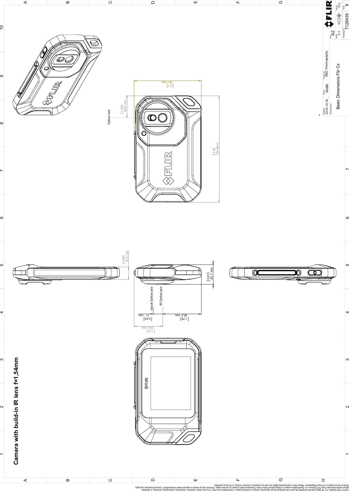
![Mechanical drawings9[See next page]#T559918; r. AL/40424/40424; en-US 40](https://usermanual.wiki/FLIR-Systems/FLIRC7200/User-Guide-3339015-Page-48.png)
![CE Declaration of conformity10[See next page]#T559918; r. AL/40424/40424; en-US 42](https://usermanual.wiki/FLIR-Systems/FLIRC7200/User-Guide-3339015-Page-50.png)