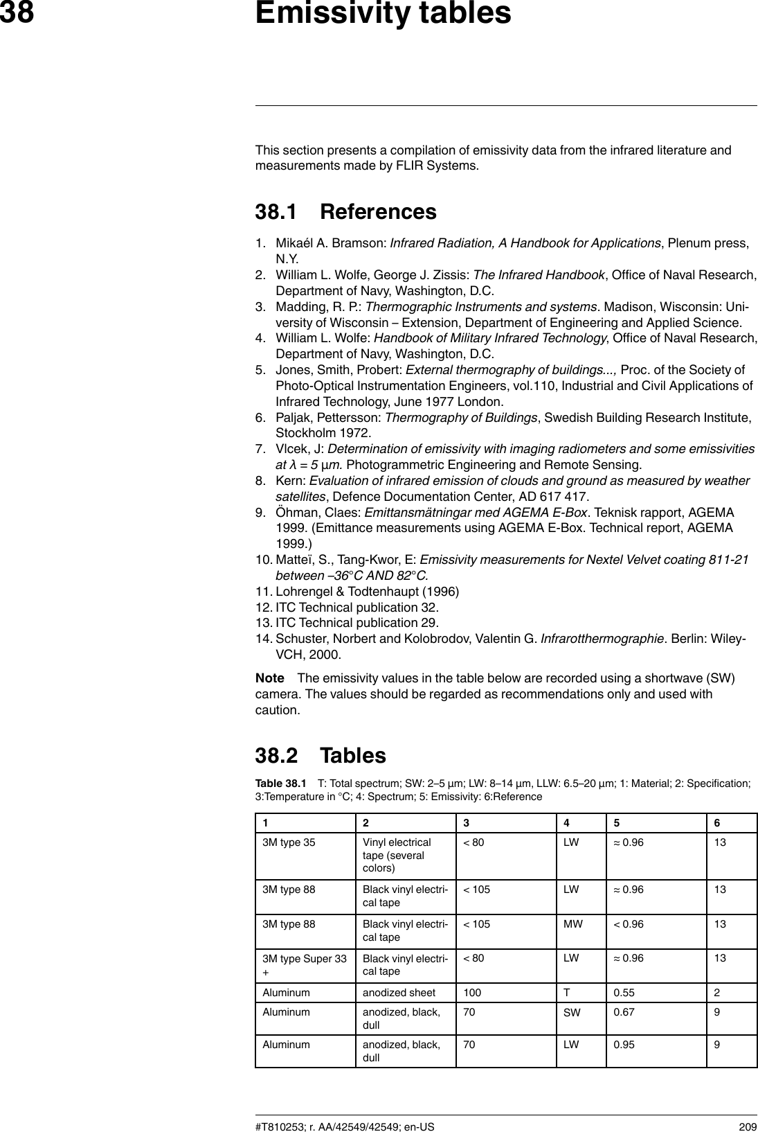
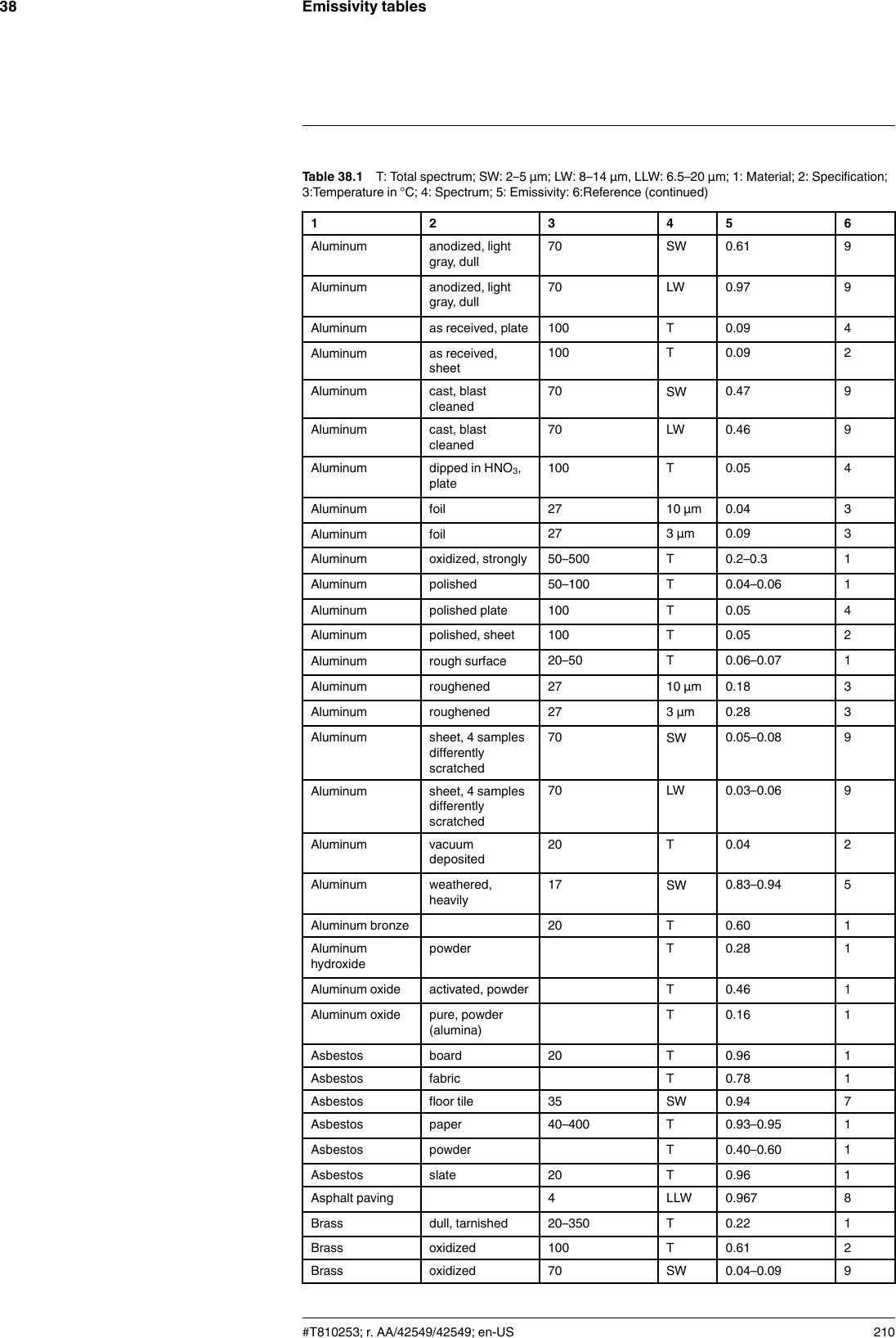
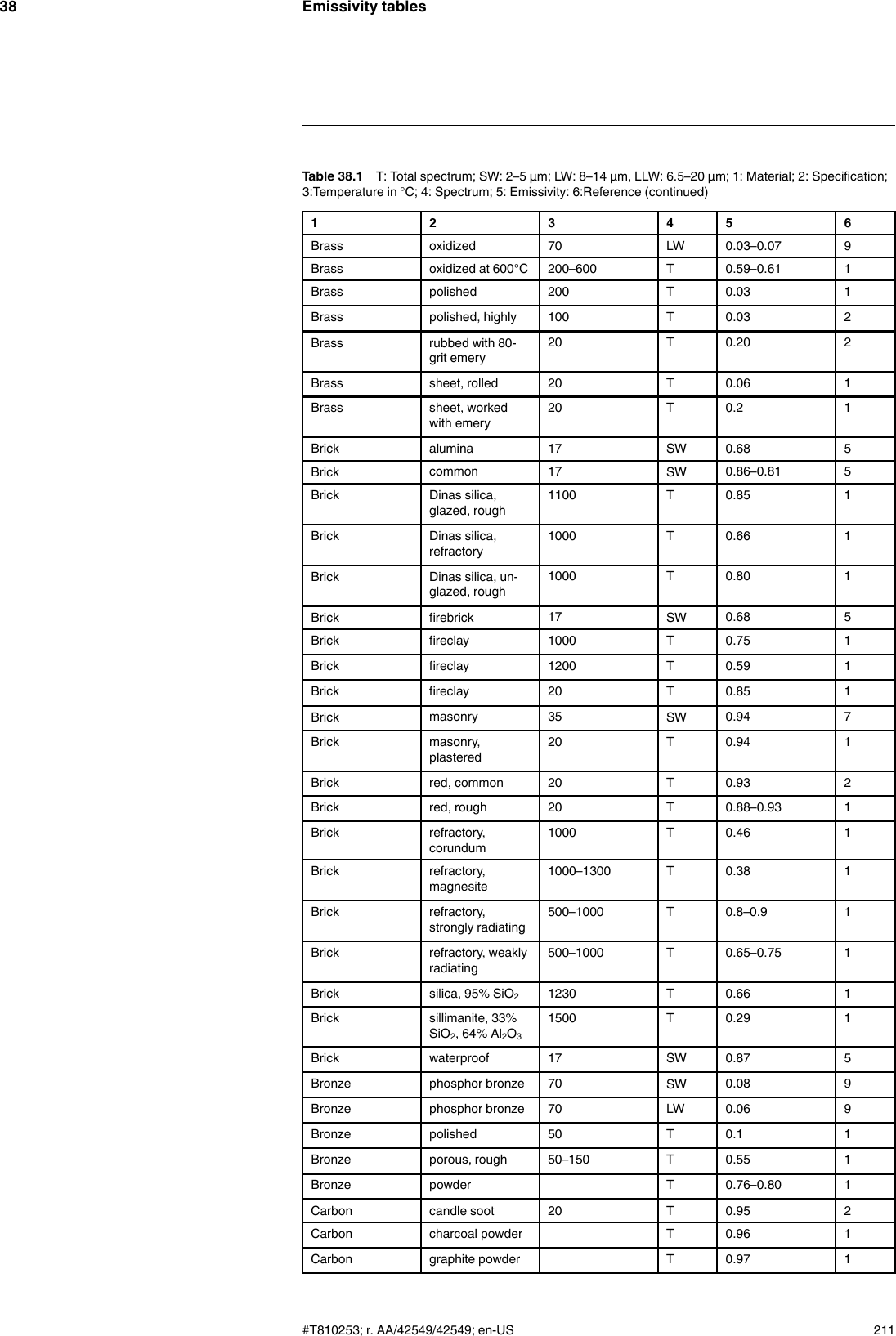
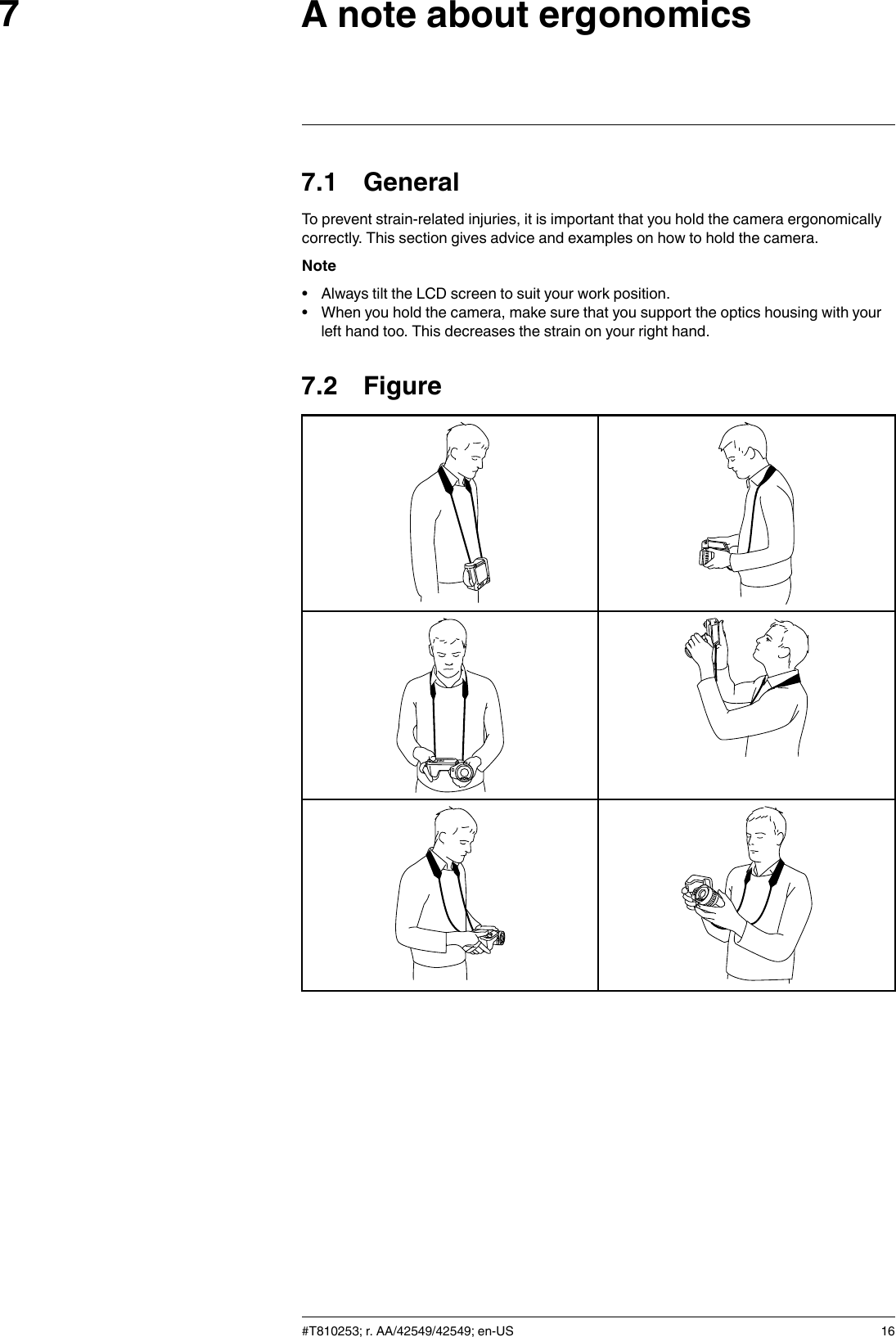
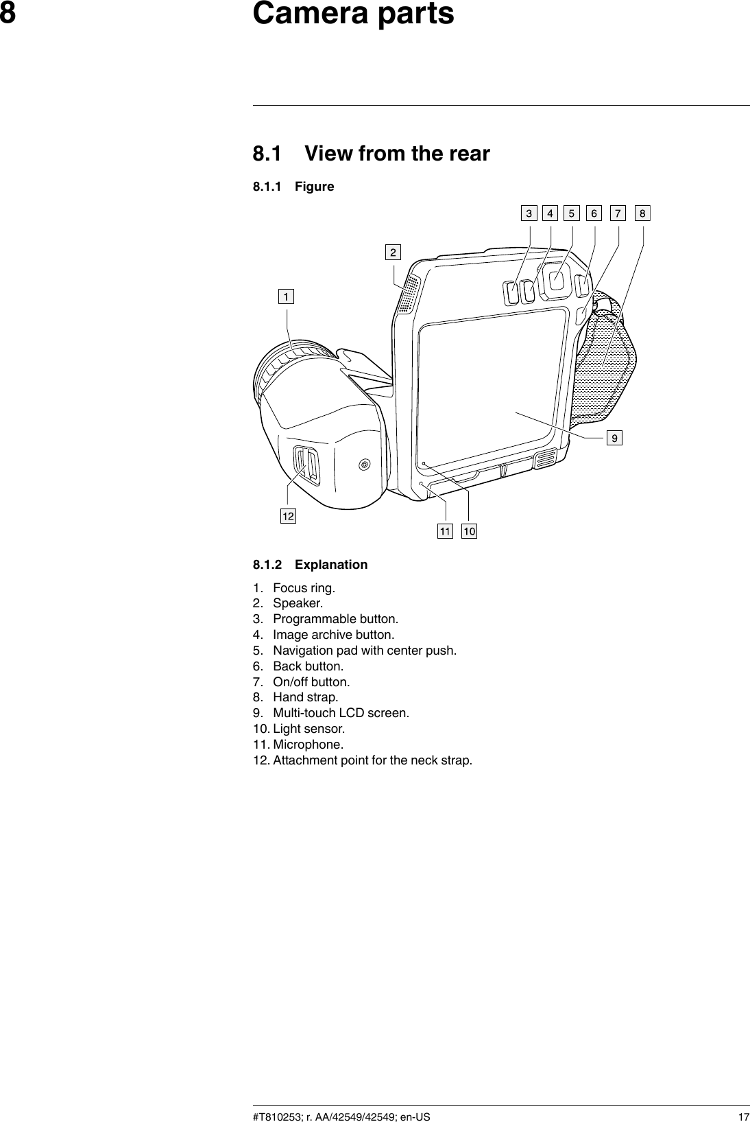
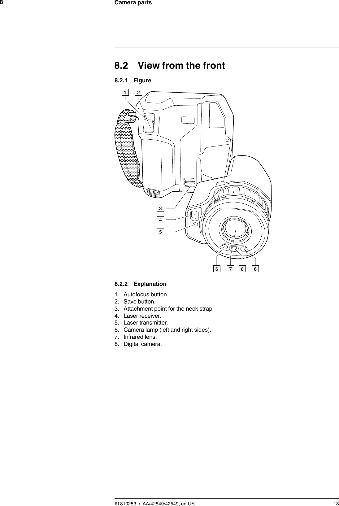
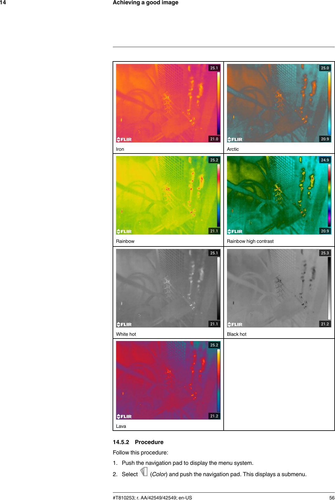
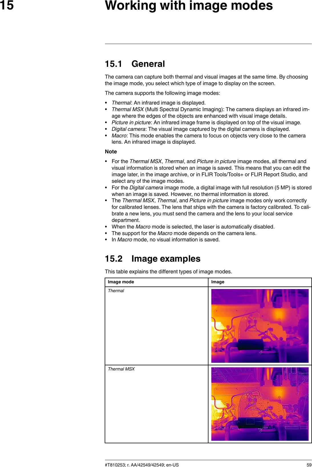
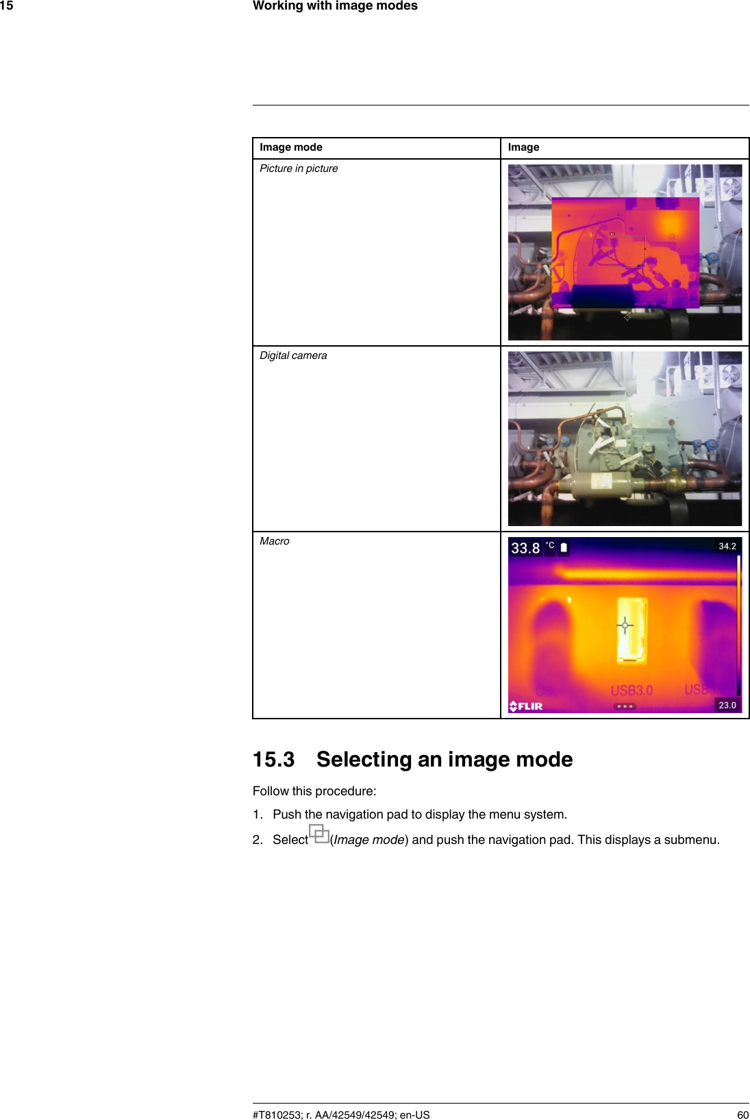
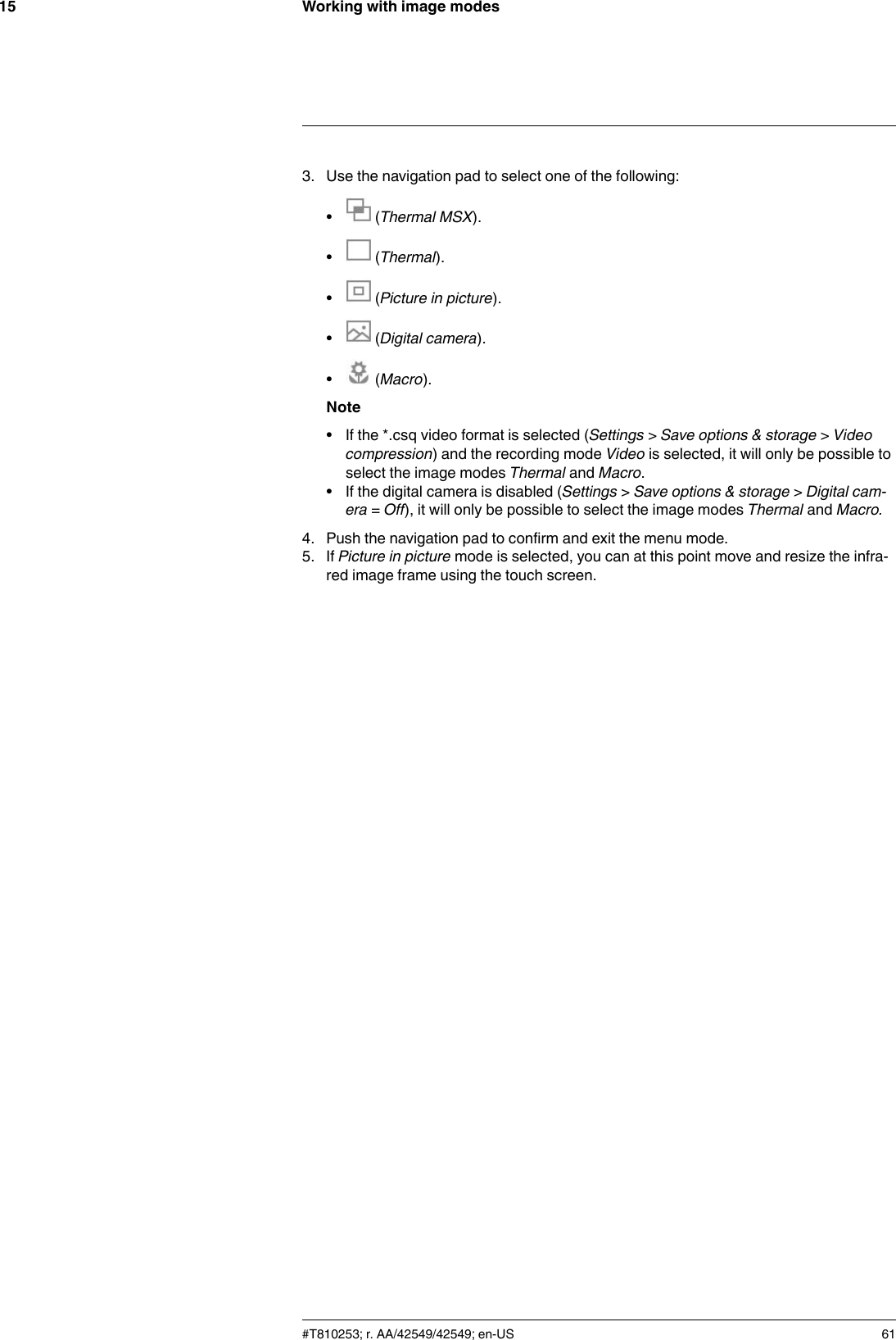
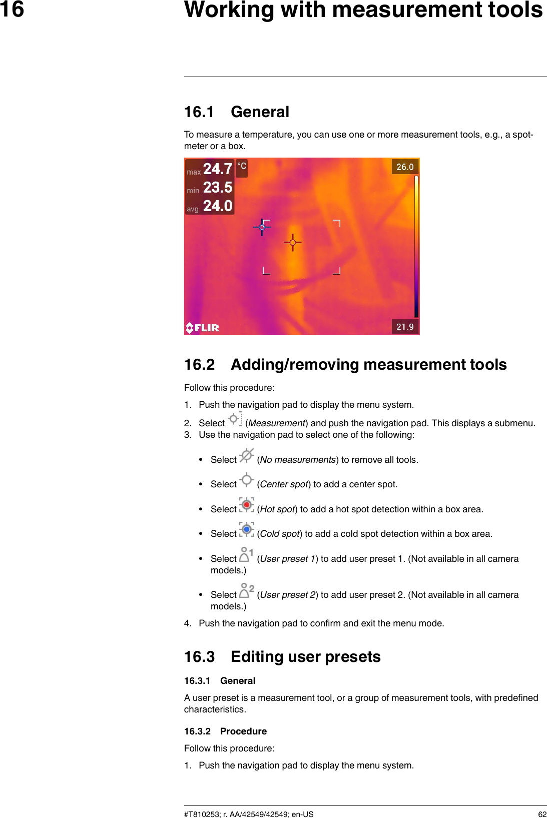
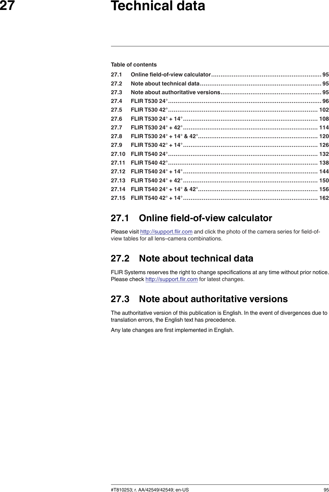
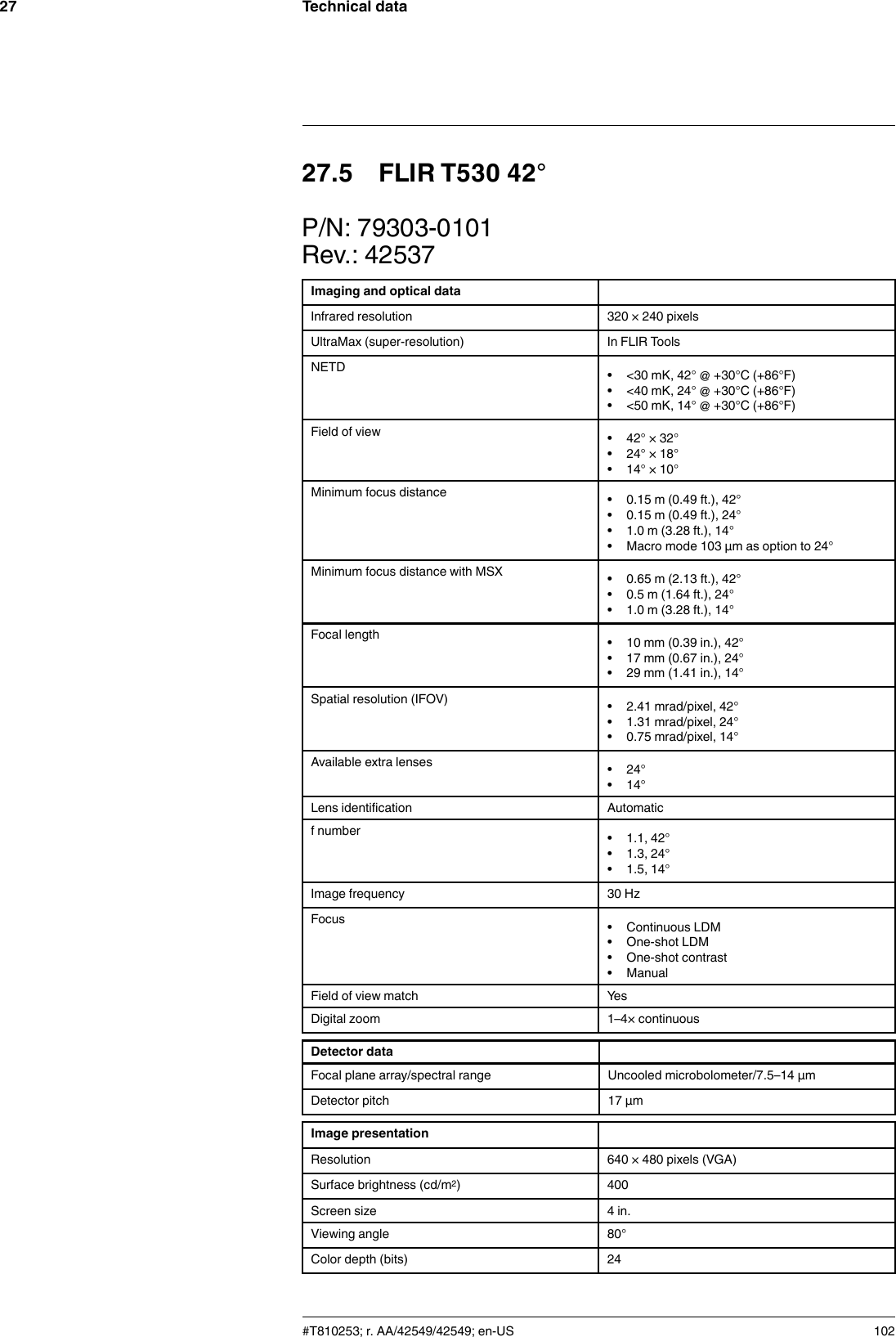
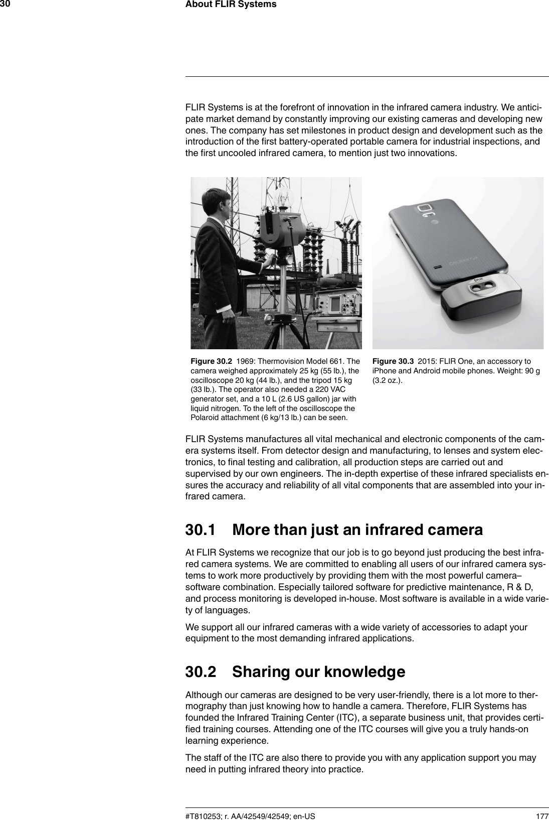
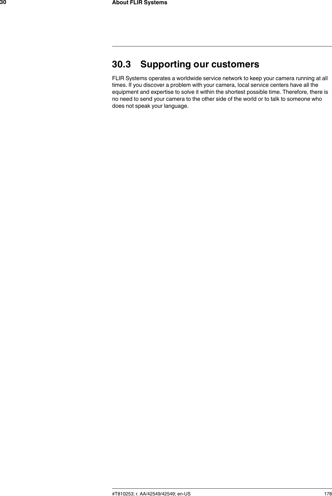
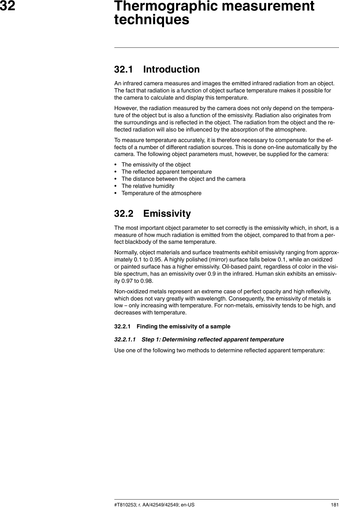
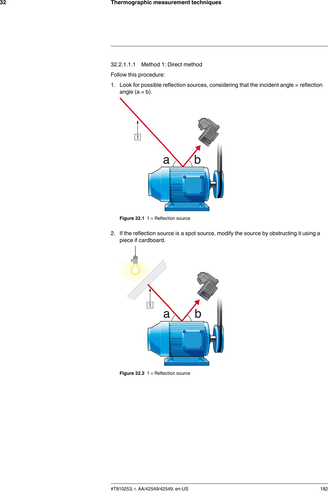
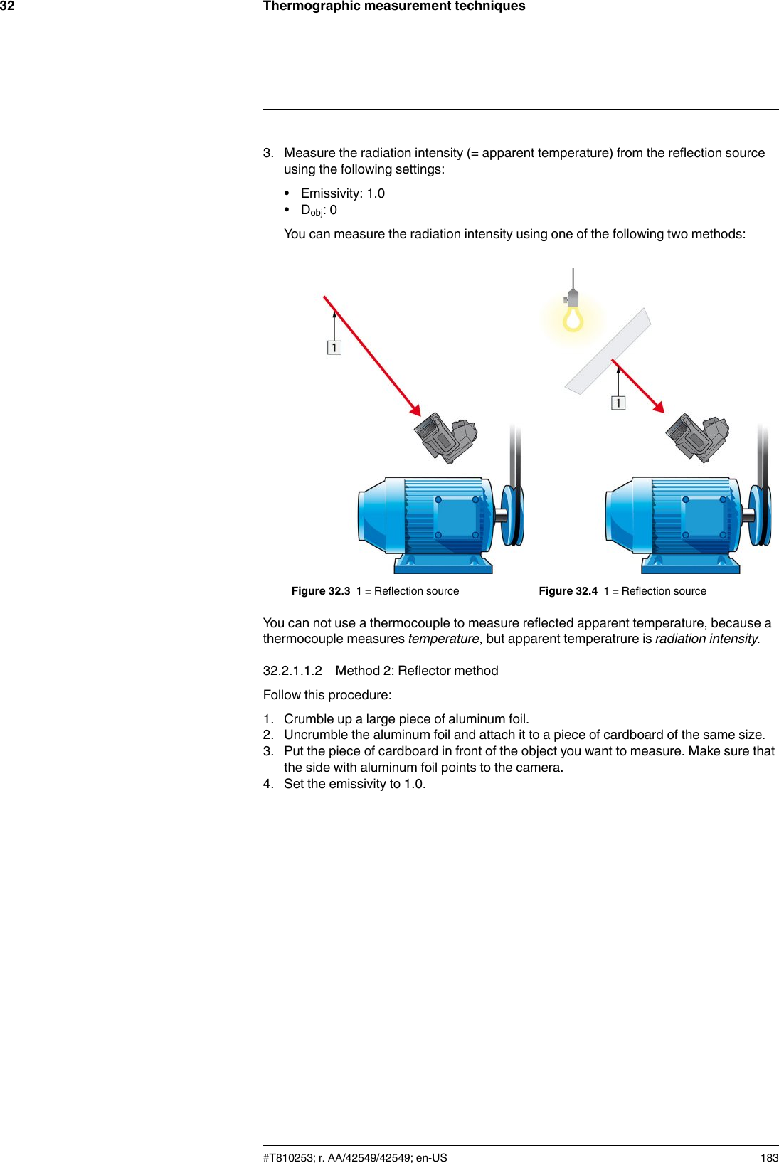
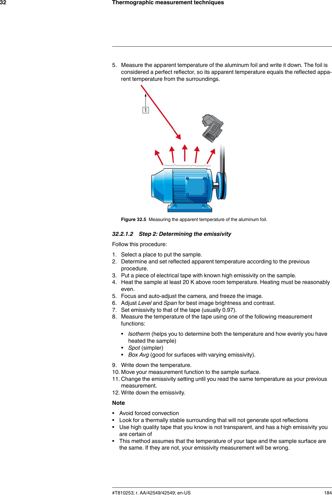
FLIR Systems FLIRT8210 Infrared Camera User Manual
FLIR Systems AB Infrared Camera
UserManual.wiki
>
FLIR Systems
>
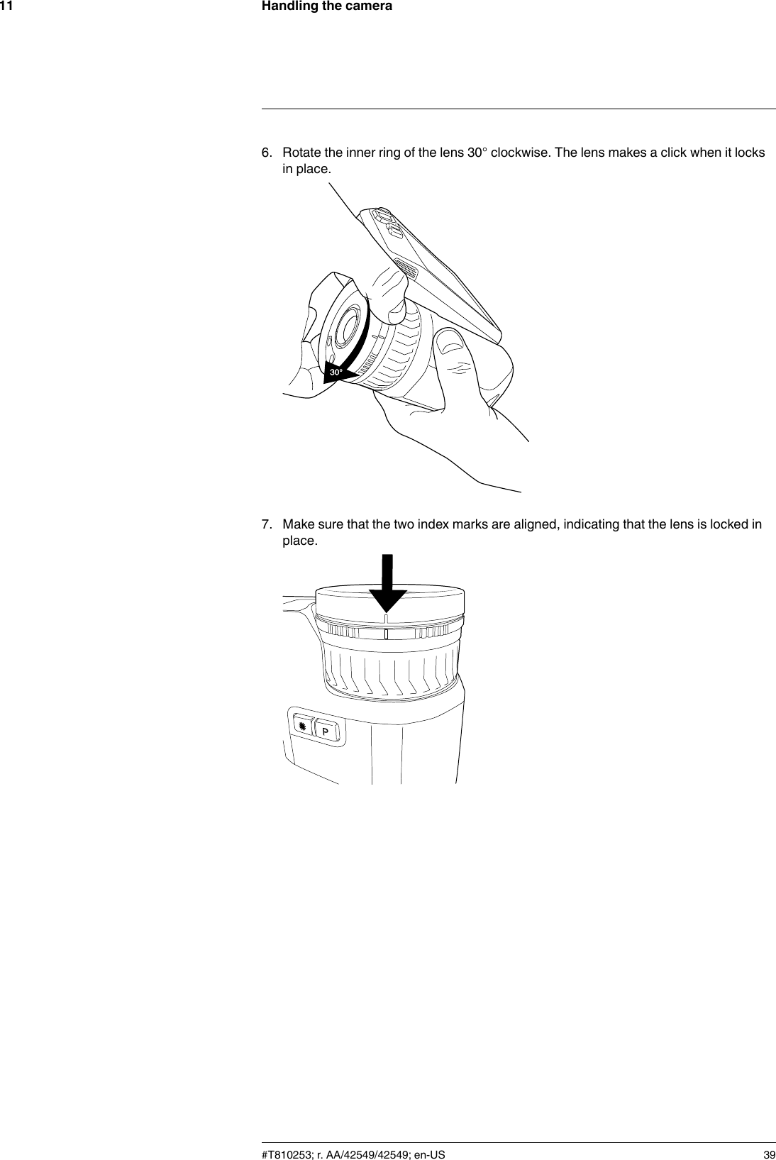
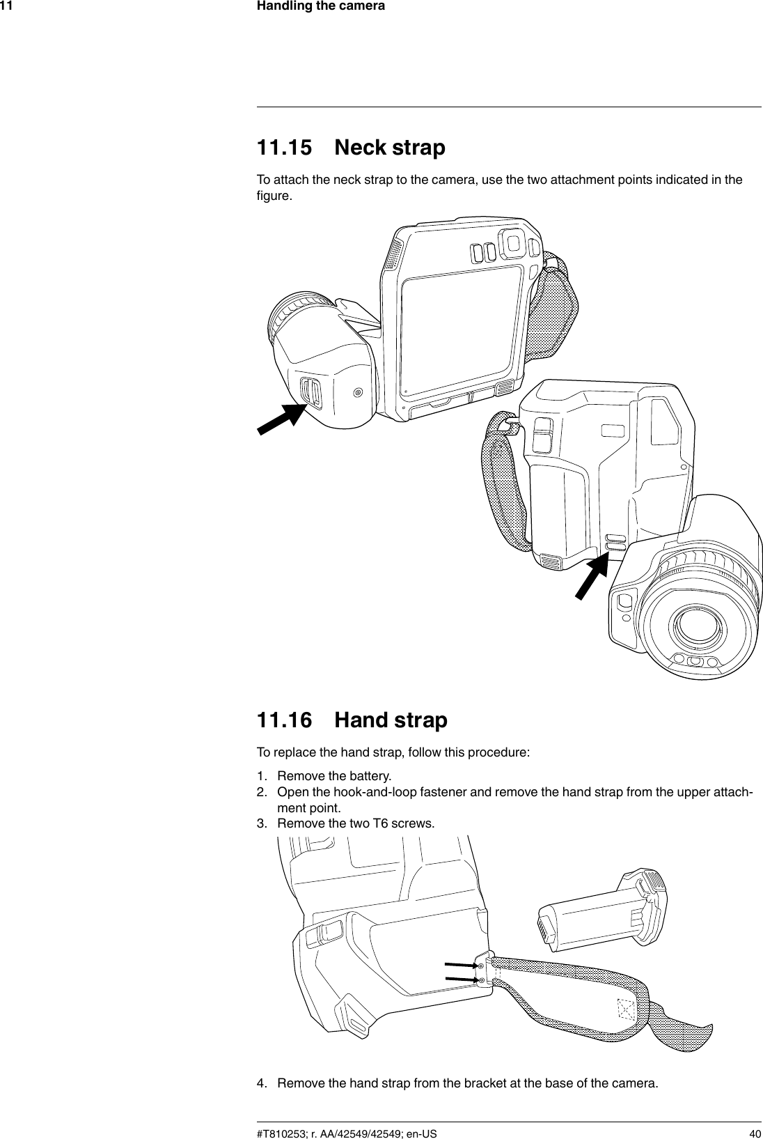
FLIRT8210 User Manual
User Manual
Navigation menu
Upload a User Manual
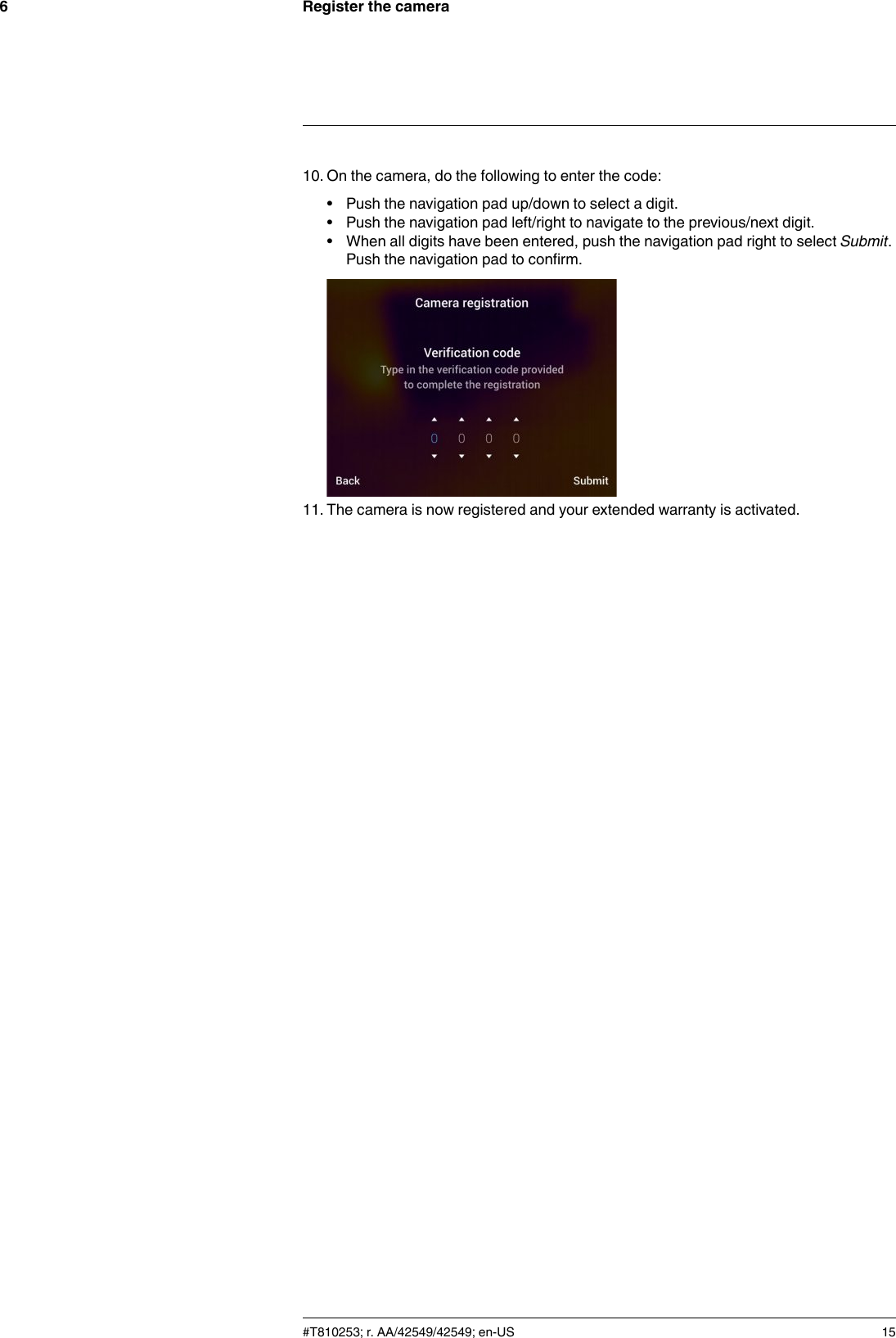
Namespaces
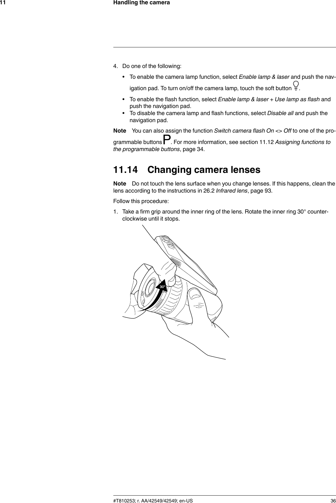
Wiki Guide
HTML
PDF
Info
Views
User Manual
Discussion / Help
Navigation


![Mechanical drawings28[See next page]#T810253; r. AA/42549/42549; en-US 168](https://usermanual.wiki/FLIR-Systems/FLIRT8210/User-Guide-3433424-Page-180.png)
![About calibration3434.1 IntroductionCalibration of a thermal camera is a prerequisite for temperature measurement. The cali-bration provides the relationship between the input signal and the physical quantity thatthe user wants to measure. However, despite its widespread and frequent use, the term“calibration” is often misunderstood and misused. Local and national differences as wellas translation-related issues create additional confusion.Unclear terminology can lead to difficulties in communication and erroneous translations,and subsequently to incorrect measurements due to misunderstandings and, in the worstcase, even to lawsuits.34.2 Definition—what is calibration?The International Bureau of Weights and Measures16 defines calibration17 in the followingway:an operation that, under specified conditions, in a first step, establishes a relation be-tween the quantity values with measurement uncertainties provided by measurementstandards and corresponding indications with associated measurement uncertaintiesand, in a second step, uses this information to establish a relation for obtaining a meas-urement result from an indication.The calibration itself may be expressed in different formats: this can be a statement, cali-bration function, calibration diagram18, calibration curve19, or calibration table.Often, the first step alone in the above definition is perceived and referred to as being“calibration.” However, this is not (always) sufficient.Considering the calibration procedure of a thermal camera, the first step establishes therelation between emitted radiation (the quantity value) and the electrical output signal(the indication). This first step of the calibration procedure consists of obtaining a homo-geneous (or uniform) response when the camera is placed in front of an extended sourceof radiation.As we know the temperature of the reference source emitting the radiation, in the secondstep the obtained output signal (the indication) can be related to the reference source’stemperature (measurement result). The second step includes drift measurement andcompensation.To be correct, calibration of a thermal camera is, strictly, not expressed through tempera-ture. Thermal cameras are sensitive to infrared radiation: therefore, at first you obtain aradiance correspondence, then a relationship between radiance and temperature. Forbolometer cameras used by non-R&D customers, radiance is not expressed: only thetemperature is provided.34.3 Camera calibration at FLIR SystemsWithout calibration, an infrared camera would not be able to measure either radiance ortemperature. At FLIR Systems, the calibration of uncooled microbolometer cameras witha measurement capability is carried out during both production and service. Cooled cam-eras with photon detectors are often calibrated by the user with special software. Withthis type of software, in theory, common handheld uncooled thermal cameras could becalibrated by the user too. However, as this software is not suitable for reporting#T810253; r. AA/42549/42549; en-US 19216.http://www.bipm.org/en/about-us/ [Retrieved 2017-01-31.]17.http://jcgm.bipm.org/vim/en/2.39.html [Retrieved 2017-01-31.]18.http://jcgm.bipm.org/vim/en/4.30.html [Retrieved 2017-01-31.]19.http://jcgm.bipm.org/vim/en/4.31.html [Retrieved 2017-01-31.]](https://usermanual.wiki/FLIR-Systems/FLIRT8210/User-Guide-3433424-Page-204.png)