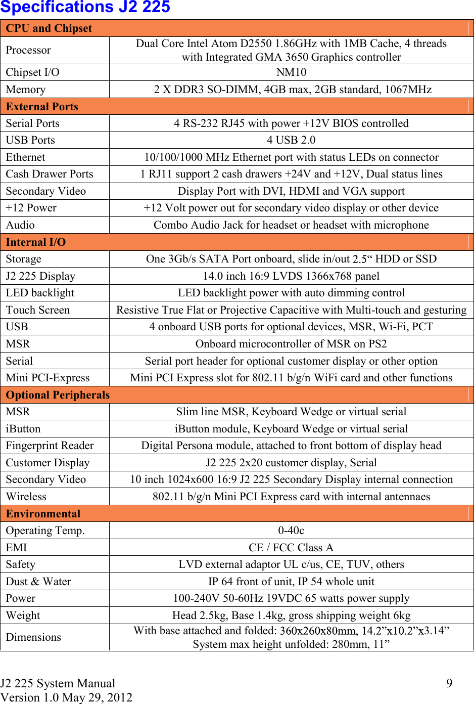
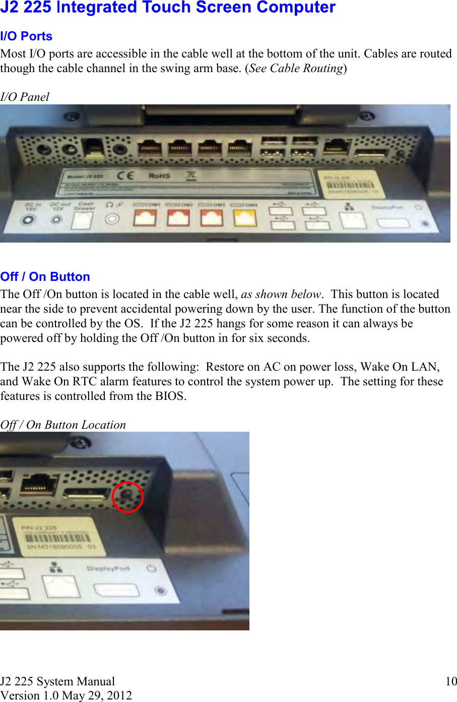
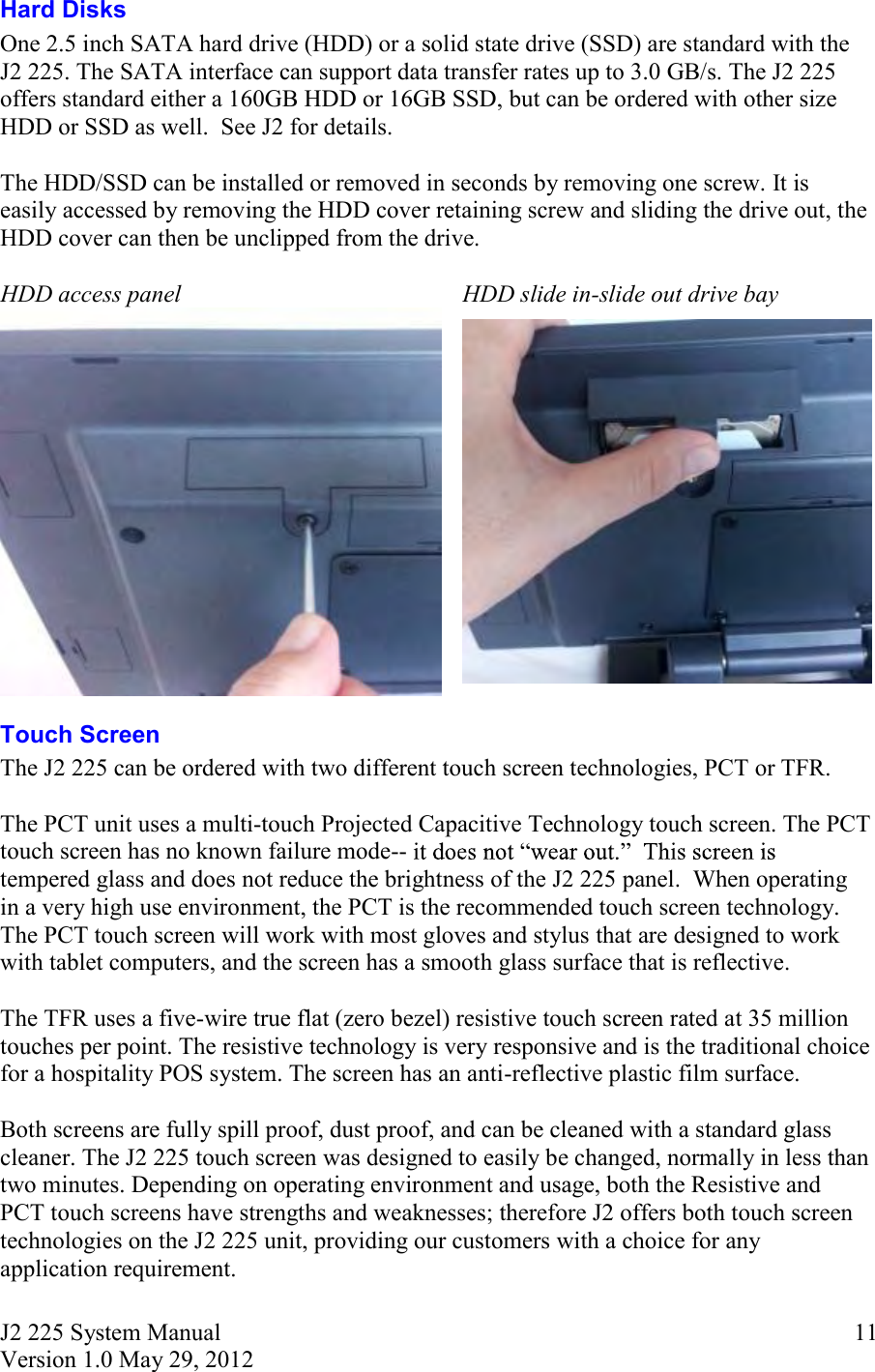
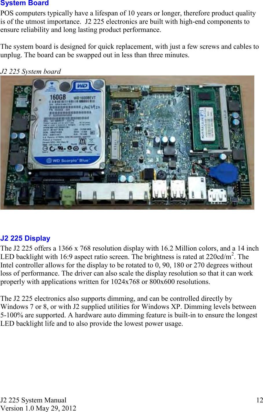
FLYTECH TECHNOLOGY J222594 POS User Manual J2 225 System Manual 1 0

FLYTECH TECHNOLOGY CO., LTD POS J2 225 System Manual 1 0

Users Manual

J2 225 Integrated Touch Screen Computer System Manual April 2012
J2 225 System Manual Version 1.0 May 29, 2012      2                    Copyright © 2012 J2 Retail Systems Ltd All rights reserved                       Change history   Version 1.0 Release May 29, 2012
J2 225 System Manual Version 1.0 May 29, 2012      3Contents  Overview ............................................................................................................................ 6  Design Concept J2 225 ...................................................................................................... 8  Specifications J2 225 ......................................................................................................... 9  J2 225 Integrated Touch Screen Computer .................................................................. 10I/O Ports ........................................................................................................................ 10Off / On Button ............................................................................................................. 10Hard Disks .................................................................................................................... 11Touch Screen ................................................................................................................ 11System Board ................................................................................................................ 12J2 225 Display ............................................................................................................... 12Secondary Video Port ................................................................................................... 13Serial ports .................................................................................................................... 14USB Ports ...................................................................................................................... 16Ethernet Connection ...................................................................................................... 16Audio ............................................................................................................................. 17Cash Drawer Ports ........................................................................................................ 17CMOS Clear .................................................................................................................. 19Mini PCI-E .................................................................................................................... 19Memory SODIMM(s) ................................................................................................... 20Power Supply ................................................................................................................ 20+12VDV Power Out ..................................................................................................... 21Typical Power Consumption J2 225 ............................................................................. 21  Service .............................................................................................................................. 22Swing Arm Base ........................................................................................................... 22Removing the Power Supply ........................................................................................ 23Cable Routing ............................................................................................................... 24VESA Mounting ........................................................................................................... 26J2 225 Disassembly Instructions ................................................................................... 27  BIOS Setting .................................................................................................................... 33Main Screen .................................................................................................................. 33System Information ....................................................................................................... 33Advanced Screen .......................................................................................................... 34Boot Configuration ....................................................................................................... 34Power Configuration ..................................................................................................... 35COM Power and LCD Brightness Configuration ......................................................... 35Security Screen ............................................................................................................. 36Boot Screen ................................................................................................................... 36Exit Screen .................................................................................................................... 37Phoenix Secure Core Tiano BIOS ................................................................................ 37
J2 225 System Manual Version 1.0 May 29, 2012      4Device Drivers ................................................................................................................. 37  OPOS Drivers .................................................................................................................. 37  J2 225 Configuration Utility .......................................................................................... 38Installation ..................................................................................................................... 38Main .............................................................................................................................. 38Power-On Hours ........................................................................................................... 39Power Cycles ................................................................................................................ 39Dim Timeout ................................................................................................................. 39Dim Brightness ............................................................................................................. 40Basic MSR Settings ...................................................................................................... 41Advanced MSR/iButton Settings .................................................................................. 42Update MCU Firmware ................................................................................................ 44MCU Option ................................................................................................................. 45  DimWake ......................................................................................................................... 46Installation ..................................................................................................................... 46  J2 Health .......................................................................................................................... 47Installation ..................................................................................................................... 47Tray Icon ....................................................................................................................... 47Logging to File .............................................................................................................. 48Registry Entries ............................................................................................................. 49J2 Remote Monitoring Software ................................................................................... 49  SMI BIOS Info Utility .................................................................................................... 50Installation ..................................................................................................................... 50Operations ..................................................................................................................... 50  Cash Drawer Test Utility ................................................................................................ 51Installation ..................................................................................................................... 51Operation ....................................................................................................................... 51  J2 Virtual Serial Ports Drivers ...................................................................................... 53  J2 225 Options ................................................................................................................. 54  J2 225 LCM 2x20 Character Customer Display .......................................................... 54Installation ..................................................................................................................... 55J2 225 LCM Configuration Utility ............................................................................... 57Installation ..................................................................................................................... 57  J2 225 MSR ...................................................................................................................... 60Installation ..................................................................................................................... 61
J2 225 System Manual Version 1.0 May 29, 2012      5J2 225 iButton Reader .................................................................................................... 63Installation ..................................................................................................................... 64  J2 225 Wall Mount / Counter-top Mount Kit .............................................................. 66Packing list .................................................................................................................... 66Assembly ....................................................................................................................... 67  J2 225 10.1 inch 1024 x 600 LCD Customer Display ................................................... 71Installation ..................................................................................................................... 72  Contact Information ....................................................................................................... 75European Office ............................................................................................................ 75USA Office ................................................................................................................... 75Australian Office ........................................................................................................... 75Website ......................................................................................................................... 75
J2 225 System Manual Version 1.0 May 29, 2012      6 The J2 225 is a new generation of integrated touch screen Point of Sale computer, brilliantly designed to be more compact and cost effective, yet rich in features and versatility. The J2 225 moves away from the traditional POS 4:3 screen form factor and uses the newer LED backlit 16:9 screen. This allows for a smaller overall physical footprint yet allows for the display of more onscreen data. Retaining the core features and capabilities of J2  other tradition POS products, like the J2 615 and J2 630 units, the J2 225 takes advantage of the newer technologies currently available.    This integrated touch screen computer, like other J2 designs, features an  -in-the-design, and it also offers the versatility to be used as a counter top unit; or as a wall-mount or pole-mounted terminal. The new smaller foot print and its unique swing arm, die cast aluminum base allows for even more flexibility, leaving more counter space for other uses. With an extremely wide range of adjustable heights and viewing angles, the versatile J2 225 can be made to work in almost any POS environment. It weighs only 3.7kg and conveniently folds flat for shipping, therefore saving customers tremendously on shipping and storing costs.  The J2 225 uses the latest Intel Atom dual core Cedarview processors, the 1.86GHz D2550. Combining this with the Intel NM10 chipset provides excellent performance capable of running most POS applications with a very low carbon foot print, all at a competitive and attractive low price.   Even with its small foot print the J2 225 is incredibly feature rich. It comes standard with 2GB of memory, and offers a choice of either a 160GB hard drive or 16GB solid state drive. Built standard with four serial ports, four USB ports, video output, audio in/out, gigabit Ethernet, +12V output, as well as other built in peripherals (like MSR, customer display and more) the J2 225 will perfectly satisfy most POS application requirements, while looking sleek and elegant in any setting.  The J2 225 is available with your choice of either a zero bezel resistive touch screen or a multi-touch projected capacitive touch screen. The new zero bezel five-wire resistive touch screen provides the same quick response and feel of a resistive touch screen traditionally used in the POS market. The new projective capacitive touch screen option can be used in environments where multi-touch and gesturing are required, for example, such as when using the new Windows 8 operating system.    The J2 225 is brilliantly designed to require little or no maintenance. The convection cooled fan-less design means it can be used in very harsh environments.  High dust, grease or sea air will not affect its operation. High temperatures are also not a problem. With a quick access HDD/SDD slot, a drive can be changed in just seconds if needed! A snap-apart design allows the unit to be fully disassembled and assembled in just a few minutes by just removing a few screws. Also available are optional Snap-on color kits, so that the J2 225 can be customized to your customer needs.
J2 225 System Manual Version 1.0 May 29, 2012      7The J2 225 supports the standard Microsoft operating systems: Windows 7, POSReady 7, Windows 7 Embedded, XP, POSReady 2009 and XP embedded, as well as the soon-to-be-released Windows 8. The J2 225 is equally proficient with the many flavors of Linux.
J2 225 System Manual Version 1.0 May 29, 2012      8  The J2 225, with its smooth modern appearance and capabilities, is perfectly suited for most low cost commodity POS touch screen computer markets. The economical price and outmatched performance will provide a great ROI for the end user, as they find it extremely dependable as well as very easy to use. MSR and Secondary Display options make it a perfect fit for companies in the POS markets, as well as for other industries, including medical and healthcare applications, among many others.    To provide the highest performance at low cost with a long product life the J2 225 unit design is based on the new Intel Atom Cedarview processor. This new 32nm part has higher speed and runs on lower power than the current offering of Atom processors for Intel.   The unit was built using as few screws as possible, providing ease of assembly and disassembly, a major design achievement. This means that the touch screen, J2 225 panel, or systems board can quickly be replaced in less than two minutes if needed (however with the solid reliability of this creative unit, this should not even be necessary.)    A major goal in the enclosure design is to keep the total size of the unit as thin and as small as possible. The thickness to the head is not much thicker that a standard notebook, except for a slight bulge in the back where the electronics are located. The aluminum die cast swing arm and fully adjustable base of the unit not only provide superb flexibility but can also easily fold flat for shipping. The shipping box for the J2 225 is no bigger than the size of an average notebook shipping box, which is also about 1/3 to 1/4 the size and weight of other POS products.   As with all J2 products our ultimate goal is always reliability. Reliability is never compromised because to reduce any cost at the expense of a dependable product would be a false economy, and we firmly stand by our outstanding engineering and designs.  We market today.
J2 225 System Manual Version 1.0 May 29, 2012      9Specifications J2 225 CPU and Chipset Processor  Dual Core Intel Atom D2550 1.86GHz with 1MB Cache, 4 threads  with Integrated GMA 3650 Graphics controller Chipset I/O  NM10 Memory   2 X DDR3 SO-DIMM, 4GB max, 2GB standard, 1067MHz External Ports Serial Ports  4 RS-232 RJ45 with power +12V BIOS controlled USB Ports  4 USB 2.0 Ethernet  10/100/1000 MHz Ethernet port with status LEDs on connector Cash Drawer Ports  1 RJ11 support 2 cash drawers +24V and +12V, Dual status lines Secondary Video  Display Port with DVI, HDMI and VGA support +12 Power  +12 Volt power out for secondary video display or other device Audio  Combo Audio Jack for headset or headset with microphone Internal I/O Storage  One 3Gb/s SATA Port onboard, slide in/out  HDD or SSD J2 225 Display  14.0 inch 16:9 LVDS 1366x768 panel  LED backlight  LED backlight power with auto dimming control Touch Screen  Resistive True Flat or Projective Capacitive with Multi-touch and gesturing  USB  4 onboard USB ports for optional devices, MSR, Wi-Fi, PCT MSR  Onboard microcontroller of MSR on PS2  Serial  Serial port header for optional customer display or other option Mini PCI-Express  Mini PCI Express slot for 802.11 b/g/n WiFi card and other functions Optional Peripherals MSR  Slim line MSR, Keyboard Wedge or virtual serial iButton  iButton module, Keyboard Wedge or virtual serial Fingerprint Reader  Digital Persona module, attached to front bottom of display head Customer Display  J2 225 2x20 customer display, Serial Secondary Video  10 inch 1024x600 16:9 J2 225 Secondary Display internal connection Wireless  802.11 b/g/n Mini PCI Express card with internal antennaes Environmental Operating Temp.  0-40c EMI  CE / FCC Class A Safety  LVD external adaptor UL c/us, CE, TUV, others Dust & Water  IP 64 front of unit, IP 54 whole unit Power  100-240V 50-60Hz 19VDC 65 watts power supply Weight  Head 2.5kg, Base 1.4kg, gross shipping weight 6kg Dimensions  With base attached and folded:  3.14  System max height unfolded: 280mm, 11
J2 225 System Manual Version 1.0 May 29, 2012      10 I/O Ports Most I/O ports are accessible in the cable well at the bottom of the unit. Cables are routed though the cable channel in the swing arm base. (See Cable Routing)  I/O Panel    Off / On Button The Off /On button is located in the cable well, as shown below.  This button is located near the side to prevent accidental powering down by the user. The function of the button can be controlled by the OS.  If the J2 225 hangs for some reason it can always be powered off by holding the Off /On button in for six seconds.  The J2 225 also supports the following:  Restore on AC on power loss, Wake On LAN, and Wake On RTC alarm features to control the system power up.  The setting for these features is controlled from the BIOS.  Off / On Button Location
J2 225 System Manual Version 1.0 May 29, 2012      11Hard Disks One 2.5 inch SATA hard drive (HDD) or a solid state drive (SSD) are standard with the J2 225. The SATA interface can support data transfer rates up to 3.0 GB/s. The J2 225 offers standard either a 160GB HDD or 16GB SSD, but can be ordered with other size HDD or SSD as well.  See J2 for details.  The HDD/SSD can be installed or removed in seconds by removing one screw. It is easily accessed by removing the HDD cover retaining screw and sliding the drive out, the HDD cover can then be unclipped from the drive.  HDD access panel HDD slide in-slide out drive bay   Touch Screen The J2 225 can be ordered with two different touch screen technologies, PCT or TFR.   The PCT unit uses a multi-touch Projected Capacitive Technology touch screen. The PCT touch screen has no known failure mode-- tempered glass and does not reduce the brightness of the J2 225 panel.  When operating in a very high use environment, the PCT is the recommended touch screen technology. The PCT touch screen will work with most gloves and stylus that are designed to work with tablet computers, and the screen has a smooth glass surface that is reflective.  The TFR uses a five-wire true flat (zero bezel) resistive touch screen rated at 35 million touches per point. The resistive technology is very responsive and is the traditional choice for a hospitality POS system. The screen has an anti-reflective plastic film surface.   Both screens are fully spill proof, dust proof, and can be cleaned with a standard glass cleaner. The J2 225 touch screen was designed to easily be changed, normally in less than two minutes. Depending on operating environment and usage, both the Resistive and PCT touch screens have strengths and weaknesses; therefore J2 offers both touch screen technologies on the J2 225 unit, providing our customers with a choice for any application requirement.
J2 225 System Manual Version 1.0 May 29, 2012      12System Board POS computers typically have a lifespan of 10 years or longer, therefore product quality is of the utmost importance.  J2 225 electronics are built with high-end components to ensure reliability and long lasting product performance.  The system board is designed for quick replacement, with just a few screws and cables to unplug. The board can be swapped out in less than three minutes.  J2 225 System board    J2 225 Display The J2 225 offers a 1366 x 768 resolution display with 16.2 Million colors, and a 14 inch LED backlight with 16:9 aspect ratio screen. The brightness is rated at 220cd/m2. The Intel controller allows for the display to be rotated to 0, 90, 180 or 270 degrees without loss of performance. The driver can also scale the display resolution so that it can work properly with applications written for 1024x768 or 800x600 resolutions.   The J2 225 electronics also supports dimming, and can be controlled directly by Windows 7 or 8, or with J2 supplied utilities for Windows XP. Dimming levels between 5-100% are supported. A hardware auto dimming feature is built-in to ensure the longest LED backlight life and to also provide the lowest power usage.
J2 225 System Manual Version 1.0 May 29, 2012      13Secondary Video Port The J2 225 supports the newer digital video standard Display Port connector. This connector supports a Display Port monitor, HDMI display, DVI or VGA monitor. When used with HMDI or DVI displays, a passive adaptor cable must be used. When using a VGA display, an active adaptor is to be used.  With HDMI display Audio, support is provided via the same HMDI cable.   The secondary video displays can be configured as Twin, Intel Dual Display Clone, or Extended Desktop. Most all monitor resolutions from 640 x 480, up to 2560 x 1600 are supported.  When the internal secondary J2 225 video display is used the secondary video port is not available.  DisplayPort Video Port
J2 225 System Manual Version 1.0 May 29, 2012      14Serial ports The J2 225 unit has four external RS232 serial ports, all of which can supply +12V power. The serial ports use a ten pin RJ45 connector. The unit comes standard with four serial cables, three  RJ45 to DB9 adapter cables, and one 152cm (5  RJ45 to DB25 serial printer cable that works with EPSON and EPSON compatible printers.   All serial (COM) ports can be BIOS-enabled to provide +12Vpower to external devices. This power is supplied via pin 10 of the RJ45 which corresponds to pin 9 on the DB9 adaptor. The maximum current per port is 1 amp, with a total maximum external loading on the +12V of 3 amps.  A set of stick-on color coded labels are supplied with the cable adaptors, so that the cables can be marked. This makes it easy to plug the cable back into the correct port, should you need to service the unit.  Serial Ports    BIOS Setting Serial Port(s) Power Enable
J2 225 System Manual Version 1.0 May 29, 2012      15RJ45 to DB9 J2 Adaptor Cable               Pin-Out when using CAT5/6 Cable                The J2 Cable Adaptor (supplied)       RJ45 to DB25 J2 Serial Pinter Cable            Pin-out when using 8 wire CAT5/6 cable Epson or Epson compatible serial printer cable    RJ45-10 Pin  DB9 Signal      RJ45- 8 Pin  DB9 Signal Pin 1  ---  ---        ---  ---  --- Pin 2  Pin 1  DCD        Pin 1  Pin 1  DCD Pin 3  Pin 6  DSR        Pin 2  Pin 6  DSR Pin 4  Pin 2  RD        Pin 3  Pin 2  RD Pin 5  Pin 7  RTS        Pin 4  Pin 7  RTS Pin 6  Pin 3  SD        Pin 5  Pin 3  SD Pin 7  Pin 8  CTS        Pin 6  Pin 8  CTS Pin 8  Pin 4  DTR        Pin 7  Pin 4  DTR Pin 9  Pin 5  GND        Pin 8  Pin 5  GND Pin 10  Pin 9  RI        ---  ---  --- RJ45-10 Pin  Signal  DB25 Signal    RJ45- 8 Pin  Signal  DB25 Signal Pin 1  ---  ---  ---    ---  ---  ---  --- Pin 2  DCD  ---  ---    Pin 1  DCD  ---  --- Pin 3  DSR  Pin 20  DTR    Pin 2  DSR  Pin 20  DTR Pin 4  RD  Pin 2  SD    Pin 3  RD  Pin 2  SD Pin 5  RTS  Pin 5  CTS    Pin 4  RTS  Pin 5  CTS Pin 6  SD  Pin 3  RD    Pin 5  SD  Pin 3  RD Pin 7  CTS  Pin 4  RTS    Pin 6  CTS  Pin 4  RTS Pin 8  DTR  Pin 6  DSR    Pin 7  DTR  Pin 6  DSR Pin 9  GND  Pin 7  GND    Pin 8  GND  Pin 7  GND Pin 10  ---  ---  ---    ---  ---  ---  ---
J2 225 System Manual Version 1.0 May 29, 2012      16USB Ports The J2 225 has 4 external and 4 internal USB 2.0 ports. The 4 external ports (see below) are located in the cable well. The 4 internal ports are used for different functions, such as using a PCT touch screen, RFID reader and/or other peripherals.     USB Ports   Ethernet Connection  The J2 225 uses the Realtek RTL8111 Gigabit Ethernet controller. The Ethernet connector is located in the cable well, as shown below. The Ethernet controller supports Wake on LAN, and the BIOS supports a PXE boot ROM as well. There is a LED on the LAN connector, this Green LED light turns on when there is LAN activity.   Ethernet Connector
J2 225 System Manual Version 1.0 May 29, 2012      17Audio The J2 225 uses the VIA1708B HD audio controller. There is one internal speaker.  A combo microphone jack and headset jack are located in the cable well of the J2 225, as seen below, which allows for the connection of a microphone and headset, or audio out to other devices.  Audio out is also supported on the DisplayPort when used with a HDMI monitor.   Audio Jack Location   Cash Drawer Ports The J2 225 is equipped with one Cash Drawer port that can support one or two drawers. This port is located in the cable well, and uses the industry standard RJ-11 connector and pin-out (illustrated below).  Cash Drawer Ports
J2 225 System Manual Version 1.0 May 29, 2012      186  1 Cash Drawer 1 Pin Assignment           Pin Signal 1 GND 2 CD1 SOLENOID 3 STATUS / STATUS CD1 4 24V 5 CD2 SOLENOID  6 GND / STATUS CD2  The application may address the Cash Drawer port in two ways:  1) Using the J2-supplied OPOS drivers for Windows.  2) Direct access to the I/O ports   Cash Drawer Controller Register  The Cash Drawer Controller use one I/O address to control the Cash Drawer.  Register Location:  48Ch           Attribute:  Read / Write         Size:  8bit                            BIT  BIT7  BIT6  BIT5  BIT4  BIT3  BIT2  BIT1  BIT0 Attribute  Read  Reserved  Write  Reserved  7  6  5  4  3  2  1  0     X  X      X  X       Reserved            Cash Drawer 1 fire             Cash Drawer 2 fire   Reserved       Cash Drawer 1 status                Cash Drawer 2 status     s on the one RJ-11 is the same as is used on Epson printers.
J2 225 System Manual Version 1.0 May 29, 2012      19CMOS Clear The J2 225 CMOS can be cleared by unplugging the system board CMOS battery for 30 seconds before plugging it back in.  CMOS Battery   Mini PCI-E  The onboard Mini PCI Express connector is normally used for the optional internal 802.11b/g/n wireless LAN card.      Mounting Screw
J2 225 System Manual Version 1.0 May 29, 2012      20Memory SODIMM(s) The J2 225 supports two SODIMM DDR3 memory sockets. The unit comes standard with 2GB of main memory and can support up to a maximum of 4GB. The memory type is DDR3 800/1066.    Power Supply The J2 225 uses a notebook-type power supply that is mounted in the base of the unit.  The power supply is rated with an output of 65 watts 18.5 VDC 3.5 Amps, and has an input rating of 100-240VAC at 50~60Hz 1.7Amps maximum.  The power supply has an efficiency rating V.  The power supply connector is a standard notebook locking type that plugs into the system power input connector, located in the cable well.  Power Input connector
J2 225 System Manual Version 1.0 May 29, 2012      21+12VDV Power Out   The J2 225 has a fused power out connector that supplies a total of 12VDC, up to 2amp.  The power supply connector is a standard notebook locking type that plugs into the system power input connector, located in the cable well, seen below  Power Input connector   Typical Power Consumption J2 225
J2 225 System Manual Version 1.0 May 29, 2012      22 Swing Arm Base The J2 225 is shipped standard with a counter top base which allows for the head to be adjusted from 0-100°, and the height can be from 8cm to 28. This allows for great versatility in height and viewing angles.                    The J2 225 swing arm base can be folded down flat for shipping, or it can also be used with the wall mounting option. Being able to fold flat greatly reduces the size of the shipping box, thereby reducing its shipping cost and storage space. When using the optional wall mount bracket, the base can be attached and allow for an adjustable viewing angle.
J2 225 System Manual Version 1.0 May 29, 2012      23The base has a lock-down screw hole to secure the base to the counter top with just a screw, or it can be attached using the wall mount bracket.    The swing arm base is only a base for the unit and is not needed for the operation of the unit. It does act as a holder for the power supply, which can be removed if the base is not needed. When not using the base, the VESA 75mm mounting points may be used to mount the J2 225.  The power supply is mounted in the base, and there are two posts to store the extra DC power cord, shown below.    Removing the Power Supply The power supply is normally located in the base but it can be removed if desired.  To remove the power supply, two screws need to be removed which hold the power supply bracket, as can be seen in the above picture.
J2 225 System Manual Version 1.0 May 29, 2012      24Cable Routing The swing arm base is designed to allow for clean cable management. There is a cable channel through the base swing arm, which has a quick access cover.    Use a coin, finger or screw driver to remove cable cover   Remove cable cover so cable can be routed
J2 225 System Manual Version 1.0 May 29, 2012      25Route cables  Replace cover
J2 225 System Manual Version 1.0 May 29, 2012      26Cables can route out via the rear of unit or through a hole in the counter top    VESA Mounting  The J2 225 unit also supports the industry standard 75mm VESA mounting. The same mounting hard point used for the swing arm base is used for VESA mounting. The four points have holes threaded for the 4mm screws.  75mm VESA Pattern
J2 225 System Manual Version 1.0 May 29, 2012      27J2 225 Disassembly Instructions  HDD access panel HDD slide in-slide out drive bay
J2 225 System Manual Version 1.0 May 29, 2012      28
J2 225 System Manual Version 1.0 May 29, 2012      29
J2 225 System Manual Version 1.0 May 29, 2012      30
J2 225 System Manual Version 1.0 May 29, 2012      31
J2 225 System Manual Version 1.0 May 29, 2012      32
J2 225 System Manual Version 1.0 May 29, 2012      33 Main Screen The main BIOS allows for the display of system information, keyboard boot options, and the setting of the time and date. The time and date may also be set via the operating system.    System Information The J2 225 BIOS has a system information screen that displays useful system information, including the serial number of the unit. This information may also be accesed via DMI utilities.    Note: This version of the new Phoenix BIOS does not have a screen shot utility yet. Please excuse the poor quality of the screen pictures. These will be replaced once the screen shot utility is available.
J2 225 System Manual Version 1.0 May 29, 2012      34Advanced Screen The Advance Screen allows for a number of BIOS options to be accessed. Please use care in changing these options, as some settings can cause the system to malfunction. These options are provided to offer maximum flexibility in configuring the J2 225. The Item Specific Help (seen on the right hand side of the screen) explains each option.    Boot Configuration
J2 225 System Manual Version 1.0 May 29, 2012      35Power Configuration The power configuration option allows for changing the behavior of the unit when it is powered up; it also enables changing the auto power-up feature.     COM Power and LCD Brightness Configuration This BIOS screen allows the enabling of the power for the serial ports, and changing the default brightness setting for the LCD screen. The LCD screen brightness can also be set via the Windows OS.
J2 225 System Manual Version 1.0 May 29, 2012      36Security Screen The Security Screen is used to set BIOS accessed passwords.    Boot Screen The boot priority order can be set with the Boot Screen.     Keys are used to view or configure devices: Use up and down arrows to select a device. A plus and minus moves the device up or down in the list. A shift plus the number 1 enables or disables the device.
J2 225 System Manual Version 1.0 May 29, 2012      37Exit Screen The exit screen allows for the saving, discarding or loading of the default BIOS settings. These functions can also be performed any time using the F9 and F10 key.    Phoenix Secure Core Tiano BIOS  The J2 225 uses the new Phoenix Secure Core Tiano BIOS. More information about this new UEFI BIOS came be found at the following web link.  http://www.phoenix.com/pages/phoenix-securecore-tiano-tm   All device drivers for the J2 225 can be downloaded from the J2 web site at: http://support.j2rs.com/225/  Installation instructions are included with each driver.    J2 supports OPOS drivers for the following J2 225 peripherals:  1: Cash Drawer(s) 2: LCM 2X20 character customer display 3: MSR Reader  The driver and documentation can be downloaded from:  http://support.j2rs.com/Utilities/OPOS/
J2 225 System Manual Version 1.0 May 29, 2012      38 The J2 225 incorporates a microcontroller (MCU) that supports a number of system functions. These include auto LCD backlight dimming, MSR encoder, iButton encoder, power LED control, power-on timer, and power cycle counter. The J2 225 Configuration Utility allows for the configuration of options and for reading the current values of these various functions.  Installation  The utility can be downloaded from the J2 web site: http://support.j2rs.com/225/utilities/ To install, simply unzip anywhere and run setup. Like other J2 utilities it can be uninstalled though the Windows control panel.  Main The main screen displays the following:  the current version of firmware, the power on count (in hours), a list of the number of power cycles, and the dim timeout setting and dim brightness settings.  ( shown below):.
J2 225 System Manual Version 1.0 May 29, 2012      39Power-On Hours The MCU uses an internal timer to keep track of how many total hours the J2 225 has been up and running in its lifetime. This number shows powered-up hours only, not the powered but off/standby time. The accuracy of this timer is only about +/- 5% and is to be used as an approximate number. The value is stored in the MCU internal EEPROM.  Power Cycles The MCU tracks the total number of times the unit has been powered off and on in the power cycle counter. The count is stored in the MCU EEPROM and is used for diagnostic purposes. The power-on and power cycles can only be changed at the factory. Dim Timeout This value is the amount of time the MCU waits if there is no touch activity before dimming the screen. This same function is built into Windows 7 and Windows 8 drivers, and should be used rather than the J2 225 hardware dimming.  But for older operating systems (such as XP) the J2 225 hardware dimming default should be used.   The default value for the hardware dim timeout is six minutes, but can be changed with this utility from any value from 0-255 minutes.  Note: a value of zero will disable the hardware auto dimming function.   Once the dim timeout is reached the LCD screen will dim to the value set in Dim Brightness. Any touch of the screen, such as MSR read, iButton read or keyboard activity that changes the keyboard LED status will take the J2 225 out of auto dim mode. This is all done via hardware, and no software drivers need to be loaded. If it is required, the J2 Dim Wake driver should be loaded if other activity is required to take the J2 225 out of auto dim. This driver is described in the Dim Wake section of this manual.
J2 225 System Manual Version 1.0 May 29, 2012      40Dim Brightness The brightness level that the screen dims to when auto dim is active is controlled by the Dim Brightness setting. This utility is used to change this value whose default value is 10%. The possible range is from 5-95%, in 5% increments.     Note: Dimming is important for a few reasons: one is to lower the total power consumption of the unit; another would be to prolong the LCD screen backlight LED life.
J2 225 System Manual Version 1.0 May 29, 2012      41Basic MSR Settings This tab is used to set commonly changed MSR/iButton settings. The default values have been chosen to work with most software without change. Note that these settings can be changed without an MSR installed. It should be noted that the MSR/iButton is a keyboard wedge device. Most settings are self-explanatory.     The radio buttons at the bottom of the screen are used to load settings to and from a file, to retrieve current settings, or to save new settingDefaults and Save to MSR  loads the default settings for the MSR/iButton and auto dimming functions.
J2 225 System Manual Version 1.0 May 29, 2012      42Advanced MSR/iButton Settings The Advanced Settings tab allows preambles and post-ambles to be added, required for the MSR and iButton. By default for the MSR, only an ENTER key needs to be sent at the end of all track data.       When preamble or postamble data needs to be edited, a touch-friendly onscreen keyboard is displayed. The data may be entered by the onscreen keyboard or by an attached keyboard. The onscreen keyboards shown below are for uppercase, lower case and control characters.
J2 225 System Manual Version 1.0 May 29, 2012      43
J2 225 System Manual Version 1.0 May 29, 2012      44Update MCU Firmware This tab is used to update the MCU firmware when necessary. This may be to add a new feature or function to the MSR/iButton. J2 will supply a firmware file for this when required.      Use the  Select Flash Firmware File  to start the update, as shown below. This will let you browse for the correct file.
J2 225 System Manual Version 1.0 May 29, 2012      45Once the hex file has been selected, touch the  Program Flash Firmware  button to start firmware update. The utility will now update the MCU firmware. It will first write the memory then verify it. Do not turn off the J2 225 power when updating.   MCU Option This tab is only used for factory programming and verification of the MCU option fuses. It will display the current value of the MCU option fuse (note that end-users normally would not use this feature).
J2 225 System Manual Version 1.0 May 29, 2012      46  DimWake is a very small and simple utility that loads on any Windows OS, but normally is only used with variations of the XP operating system (like XP Pro, POSReady 2009, WEPOS, or XP Embedded). The DimWake program is used to take the J2 225 out of auto dim mode. The hardware can only take the system out of dimming by either a touch of the touch screen, MSR read, iButton read, or keyboard activity that changes the keyboard LED status. Sometimes it is desirable for other events to take the system out of dim mode, like a mouse movement. The DimWake program provides this function.  Installation  The utility can be downloaded from the J2 web site: http://support.j2rs.com/225/utilities/ To install just unzip anywhere and run setup. Like other J2 utilities it can be uninstalled through the Windows control panel.  Once having installed DimWake, you will need to reboot the system for it to take effect. DimWake will then be running in the background.   Once installed and running - any mouse, keyboard or high CPU activity (like playing a video) will bring hardware auto dimming out of dimming mode, or prevent it from going in to dimming. This combination of hardware auto dimming and DimWake provides that same function to XP, as comes standard with Windows 7 and Windows 8. When using Windows 7 or 8 it is best to use the built-in dimming feature.
J2 225 System Manual Version 1.0 May 29, 2012      47 J2 has a standard program that works with all its POS products, called J2 Health. This program is used in either a standalone mode or in conjunction with J2 remote monitor/asset tracking software. The J2 Health program monitors different aspects of the POS hardware to ensure the hardware is running within specification. For the J2 225 it monitors critical system voltages, as well as system and CPU temperatures. Installation  The utility can be downloaded from the J2 web site: http://support.j2rs.com/Utilities/Health/  To install just unzip anywhere and run setup. Like other J2 utilities it can be uninstalled through the Windows control panel.  Tray Icon Once installed and the system has rebooted, J2 Health will be running in the background. The J2 health icon will appear in the task bar tray:     Right-clicking on this icon displays different Health options, shown below:     The current health values will display by clicking   A sample screen is shown below:
J2 225 System Manual Version 1.0 May 29, 2012      48  As can be seen above, when running on the J2 225 the J2 Health program displays critical system voltages and system and CPU Core temperatures. For other J2 POS systems, J2 Health may display more or less information. An example would be the J2 680 unit, which in addition to the above information would also display the fan speed of the two J2 680 fans. Logging to File The J2 Health program can log the health data to a file in the csv text format for importing to other programs, like Excel. This can be handy for finding  time of day  related problems.   When logging is enabled, the tray icon Rx symbol will change to red to indicate logging in is taking place.
J2 225 System Manual Version 1.0 May 29, 2012      49Registry Entries The J2 Health program creates registry entries for the different health values. Dynamic values are updated at the user defined interval, which is by default 5 seconds. Other software may use these registry entries to access the J2 health information. J2 225 Health keys are shown below:     J2 Remote Monitoring Software J2 now offers a full remote monitoring and asset tracking solution that works in conjunction with J2 Health to ensure the highest uptime possible of your POS hardware.  Please contact J2 sales for more information on this fully customizable, remote monitoroption. For more information, please visit us at http://www.j2retailsystems.com/newsarticle.php?news_id=57
J2 225 System Manual Version 1.0 May 29, 2012      50 The J2 SMI BIOS Info program allows for the reading of all populated BIOS DMI/SMI information. With some J2 products including the J2 225, this information also includes dynamic system health information. Normally this dynamic DMI health information BIOS is only supported on very high end servers. Now J2 brings this feature to POS hardware.   The J2 SMI BIOS Info program will run on any J2 POS hardware or for that fact on any PC hardware. It can display all DMI/SMI information on a formatted form. Installation  The utility can be downloaded from the J2 web site: http://support.j2rs.com/Utilities/ To install just unzip anywhere and run as you wish to run the utility form. Operations Just click on the .exe file to run. The following screen will be displayed (see below).  Note that the health data will only display on newer J2 systems that support the dynamic DMI health BIOS.
J2 225 System Manual Version 1.0 May 29, 2012      51 J2 has a generic cash drawer test utility that works on all J2 products, including the new J2 225 computer. This test program also supports the J2 225 separate status lines, such as when   is used, supporting two cash drawers.   Installation  The utility can be downloaded from the J2 web site: http://support.j2rs.com/Utilities/ To install just unzip anywhere and run as you wish to download the utility form.  Operation Just run the cash drawer test from whatever folder it was installed into(See example below)
J2 225 System Manual Version 1.0 May 29, 2012      52 To use two cash drawers with the J2 225 you use cable that also works with Epson printers or  s separate status lines (The standard cable supports shared status lines.). When using the look like this:     option is to test the cash drawer you set up using the J2 virtual serial ports program. The virtual serial port program must be installed with the cash drawer virtual serial ports set to Comm 10 & 11.
J2 225 System Manual Version 1.0 May 29, 2012      53    Virtual serial ports can be used for the cash drawers, virtual 2x20 line display on the optional 10.1 LCD, Smart UPS, MSR and iButton.    To open virtual serial cash drawer send a bell character to the Com port it is assigned to.  (The bell chathe drawer may be obtained by reading the status bits of its COM port. The drawer open/close status will be reflected on the CTS and RI bits, either bit may be used. This virtual COM port driver is designed to work the same as a hardware serial cash drawer and will work with drivers for serial cash drawers.
J2 225 System Manual Version 1.0 May 29, 2012      54  The J2 225 supports an optional two line by twenty character mono color liquid crystal display module (LCM). This LCM display shows black characters on a white background for maximum visibility to the customer. The LCM supports a number of firmware emulations of popular customer displays which allows existing POS software to run without modification.
J2 225 System Manual Version 1.0 May 29, 2012      55Installation The J2 225 LCM can be installed in just a minute. To install: first power down the system, then remove the secondary display mounting cover (as shown below):
J2 225 System Manual Version 1.0 May 29, 2012      56After the secondary display cover is removed, attach the LCM cable to the unit.           This 8-pin cable plugs into the CN8 / LCM connector on the system board. The connector is keyed so that it can only plug in one way. This cable provides power and serial data to the LCM module.    Once the cable is plugged in, feed any extra cable into the unit and attach the LCM with the two 4mm screws provided with the display.
J2 225 System Manual Version 1.0 May 29, 2012      57The system can now be powered on. When power is first applied, the LCB will display its current settings before clearing and will wait for serial data from the system.       J2 225 LCM Configuration Utility A configuration utility is provided to change the LCM setting. This utility allows for the setting of serial port bard rate, a data format as well as emulation type and default font. It also allows for the LCM firmware to be updated if required.  Installation  The utility can be downloaded from the J2 web site: http://support.j2rs.com/Utilities/  To install just unzip anywhere and run setup. Like other J2 utilities it can be uninstalled through the Windows control panel.
J2 225 System Manual Version 1.0 May 29, 2012      58By default the LCM is mapped to ComPort 6, 9600 baud and N-8-1 parity.     The emulation, character set, baud rate and parity can be changed under CD Settings.
J2 225 System Manual Version 1.0 May 29, 2012      59the necessary file should a firmware update be required.
J2 225 System Manual Version 1.0 May 29, 2012      60 The J2 225 supports an optional magnetic card reader (MSR). This reader supports magnetic stripe cards conforming to ISO 7811/1-6. It can read both high & low coercivity magnetic stripes. The MSR support 3 tracks of data but defaults to having only track one and two enabled. The MSR is a Keyboard Wedge device with all data being sent to the keyboard port. For software that requires a serial port MSR, the J2 Virtual Serial Port driver can be used to allow the J2 225 MSR to function as a serial port MSR.
J2 225 System Manual Version 1.0 May 29, 2012      61Installation The J2 225 MSR can be installed in just a minute. To install, first power down the system. Then remove the option mounting point cover, as shown below:
J2 225 System Manual Version 1.0 May 29, 2012      62Once the cover is removed, plug in the cable MSR cable.    Once the cable is attached, the MSR may be screwed onto the unit using the 2 screws provided. Make sure the MSR cable is not being pinched when attaching the MSR.   This completes the installation of the J2 225 optional MSR.  Note that the MSR can be mounted to any one of the J2 225 option mounting points. By default the internal MSR cable is routed to the upper right hand corner of the unit, however this cable can be rerouted if need be to use any of the other three option mounting points.  The software configuration of the MSR is covered under the J2 225 Configuration Utility section of this manual.
J2 225 System Manual Version 1.0 May 29, 2012      63 J2 225 supports an optional iButton reader, sometimes referred to as a Dallas key. The iButton is a Keyboard Wedge device with all data being sent to the keyboard port. For software that requires a serial port iButton reader, the J2 Virtual Serial Port driver can be used to allow the J2 225 iButton reader to function as a serial port iButton reader.
J2 225 System Manual Version 1.0 May 29, 2012      64 Installation The J2 225 iButton reader can be installed in just a minute. To install, first power down the system, then remove the option mounting point cover, as shown below:       Plug in the ibutton cable as shown:.
J2 225 System Manual Version 1.0 May 29, 2012      65Attach the iButton reader onto the unit with the 2 screws provided.  Make sure the cable is not being pinched when attaching the iButton reader.     This completes the installation of the J2 225 optional iButton reader.    Note that the iButton reader can be mounted to any one of the J2 225 mounting option points. By default the internal iButton reader cable is routed to the upper right hand corner of the 225, but this cable can be rerouted if need be to use any of the other three option mounting points.  The software configuration of the iButton reader is covered under the J2 225 Configuration Utility section of this manual.
J2 225 System Manual Version 1.0 May 29, 2012      66-  The J2 225 has available an optional kit for wall mounting the unit when not using the VESA mounts. This kit has the advantage that it works together with the J2 225 standard base to allow the viewing angle and distance from the wall to be adjusted. Also the power supply is mounted in the base making for a clean install. This same kit can also be used as a way of securely mount the unit to a counter top or other surfaces.  Packing list The wall mount come with the following parts:  Qty Part 8 3 mm screws 4 Mounting Clips 1 4 mm screw 1 Mounting Bracket
J2 225 System Manual Version 1.0 May 29, 2012      67Assembly First attach the four mounting clips using the 3 mm screws, as shown below:   Next attach the mounting bracket to the wall or other surface using at least four of the bracket mounting holes. Please note that the bracket has both a 100mm and 75mm hole pattern, so that the bracket can be used with the VESA bracket as well as being directly mounted to a wall. Be sure to use a mounting screw with sufficient hold force for the material being mounted to and allow for the stress of the adjustment of the swing arm base.  UP
J2 225 System Manual Version 1.0 May 29, 2012      68Next the J2 225 can be hung on the bracket by sliding the unit down on the bracket so it catches on all four mounting clips, as illustrated below. This will need to be done by feel, of course, as you will not be able to see the clips engage.  Next step is to route any cables you need to go to the unit as required. A space is provided just by the power supply for the cable to exit cleanly, assuming they are routed via the swing arm cable channel as in a normal install. Cables can also be routed down as well. Be sure cables are clear or protected of any sharp surfaces. You can remove the unit on and off the wall mount bracket as needed to route the cables.    Cables can exit the top or bottom when routed between the bracket and unit. A wall hole could be used to cover the cables in the power supply area.
J2 225 System Manual Version 1.0 May 29, 2012      69The final step is to install the locking safety screw. This screw is to insure the unit is not knocked of the wall by accident . The 4 mm screw supplied is used for this propose. First remove the rubber hole plug from the unit, then screw in the safety screw. The unit is now secure enough and the swing base can be adjusted to the desired viewing angle.  Rubber Screw Cover    Safety Screw Location
J2 225 System Manual Version 1.0 May 29, 2012      70Some possible viewing angles using the wall mount bracket.
J2 225 System Manual Version 1.0 May 29, 2012      71 The J2 225 supports an optional customer side LCD display. This display attaches to an internal DisplayPort via short cable that support power and data to the display. The display resolution is 1024 x 600 16:9. This display is the same type as used as on many Netbook computers.  10.1 inch 16:9 Customer Display
J2 225 System Manual Version 1.0 May 29, 2012      72Installation The J2 225 10.1 display can be installed in just a minute. To install: first power down the system, then remove the secondary display mounting cover (as shown below):
J2 225 System Manual Version 1.0 May 29, 2012      73This 20-pin cable plugs into the CN6 connector on the system board. The connector is keyed so that it can only plug in one way. This cable provides power and video data to     Once the cable is plugged in, feed any extra cable into the unit and attach the LCM with the two 4mm screws provided with the display.
J2 225 System Manual Version 1.0 May 29, 2012      74Configure the Intel video driver for extended desktop with the 1024 x 600 display as the secondary display.  The secondary display brightness will follow the main screen brightness unless disable by a jumper on the 10.1 display electroins.    J2 also supplies display. This allows part of the screen to display data that would normal be used on a 2 x 20 display while using the rest of the display for advertising content.
J2 225 System Manual Version 1.0 May 29, 2012      75  European Office  J2 Retail Systems Ltd. J2 House Clayton Road, Birchwood Warrington   WA3 6RP United Kingdom  44 (0) 1925 817003 Phone 44 (0) 1925 811989 Fax  USA Office  J2 Retail Systems Inc. 9251 Irvine Boulevard  Irvine, CA 92618 USA   Australian Office  J2 Retail Systems Pty Ltd Unit 6 83/85 Boundary Road Mortdale NSW 2223 Australia  02 9584 5222 Phone 02 9584 1500 Fax  Website  http://www.j2retailsystems.com
FCC StatementThis equipment has been tested and found to comply with the limits for a Class A digital device, pursuant to Part 15 of the FCC Rules.  These limits are designed to provide reasonable protection against harmful interference when the equipment is operated in a commercial environment.  This equipment generates, uses, and can radiate radio frequency energy and, if not installed and used in accordance with the instruction manual, may cause harmful interference to radio communications.  Operation of this equipment in a residential area is likely to cause harmful interference in which case the user will be required to correct the interference at his own expense.This device complies with FCC radiation exposure limits set forth for an uncontrolled environment.This device complies with Part 15 of the FCC Rules. Operation is subject to the following two conditions: (1) this device may not cause harmful interference, and (2) this device must accept any interference received, including interference that may cause undesired operation.Caution! Any changes or modifications not expressly approved by the party responsible for compliance could void the user's authority to operate the equipment.

Navigation menu