FLYTECH TECHNOLOGY K936C73 Bedside Terminal Hardware System User Manual K936 V1 1 1201
FLYTECH TECHNOLOGY CO., LTD Bedside Terminal Hardware System K936 V1 1 1201
Users Manual
Version 1.1 September 2014
Bedside Terminal
Hardware System
User Manual
Copyright 2014
All Rights Reserved
Manual Version 1.1
The information contained in this document is subject to change without notice.
We make no warranty of any kind with regard to this material, including, but not
limited to, the implied warranties of merchantability and fitness for a particular
purpose. We shall not be liable for errors contained herein or for incidental or
consequential damages in connection with the furnishing, performance, or use of
this material.
This document contains proprietary information that is protected by copyright. All
rights are reserved. No part of this document may be photocopied, reproduced or
translated to another language without the prior written consent of the
manufacturer.
TRADEMARK
Intel®, Pentium® and MMX are registered trademarks of Intel® Corporation.
Microsoft® and Windows® are registered trademarks of Microsoft Corporation.
Other trademarks mentioned herein are the property of their respective owners.

Safety
IMPORTANT SAFETY INSTRUCTIONS
1. To disconnect the machine from the electrical Power Supply, turn off the power
switch and remove the power cord plug from the wall socket. The wall socket
must be easily accessible and in close proximity to the machine.
2. Read these instructions carefully. Save these instructions for future reference.
3. Follow all warnings and instructions marked on the product.
4. Do not use this product near water.
5. Do not place this product on an unstable cart, stand, or table. The product may
fall, causing serious damage to the product.
6. Slots and openings in the cabinet and the back or bottom are provided for
ventilation; to ensure reliable operation of the product and to protect it from
overheating. These openings must not be blocked or covered. The openings
should never be blocked by placing the product on a bed, sofa, rug, or other
similar surface. This product should never be placed near or over a radiator or
heat register, or in a built-in installation unless proper ventilation is provided.
7. This product should be operated from the type of power indicated on the marking
label. If you are not sure of the type of power available, consult your dealer or
local power company.
8. Do not allow anything to rest on the power cord. Do not locate this product where
persons will walk on the cord.
9. Never push objects of any kind into this product through cabinet slots as they
may touch dangerous voltage points or short out parts that could result in a fire
or electric shock. Never spill liquid of any kind on the product.
10. To avoid the risk of electric shock, this equipment must only be connected to a
supply mains with protective earth.)
11. No modification of this equipment is allowed.
CE MARK
This device complies with the requirements of the EEC directive 2004/108/EC
with regard to “Electromagnetic compatibility” and 2006/95/EC “Low Voltage
Directive”
FCC
This device complies with part 15 of the FCC rules. Operation is subject to the
following two conditions:
(1) This device may not cause harmful interference.
(2) This device must accept any interference received, including interference that
may cause undesired operation
UL
This equipment has been tested and found to comply with the limits for a Class
B digital device, pursuant to part 15 of the FCC Rules. These limits are designed to
provide reasonable protection against harmful interference in a residential
installation.
This equipment generates, uses and can radiate radio frequency energy and, if not
installed and used in accordance with the instructions, may cause harmful
interference to radio communications. However, there is no guarantee that
interference will not occur in a particular installation. If this equipment does cause
harmful interference to radio or television reception, which can be determined
by turning the equipment off and on, the user is encouraged to try to correct the
interference by one or more of the following measures:
—Reorient or relocate the receiving antenna.
—Increase the separation between the equipment and receiver.
—Connect the equipment into an outlet on a circuit different from that to which the
receiver
is connected.
—Consult the dealer or an experienced radio/TV technician for help
CAUTION ON LITHIUM BATTERIES
There is a danger of explosion if the battery is replaced incorrectly. Replace only with
the same or equivalent type recommended by the manufacturer. Discard used
batteries according to the manufacturer’s instructions.
Battery Caution
Risk of explosion if battery is replaced by an incorrectly type.
Dispose of used battery according to the local disposal instructions.
Safety Caution
Note: To comply with IEC60950-1 Clause 2.5 (limited power sources, L.P.S) related
legislation, peripherals shall be 4.7.3.2 "Materials for fire enclosure" compliant.
4.7.3.2 Materials for fire enclosures
For MOVABLE EQUIPMENT having a total mass not exceeding
18kg.the material of a FIRE ENCLOSURE, in the thinnest significant
wall thickness used, shall be of V-1 CLASS MATERIAL or shall pass
the test of Clause A.2.
For MOVABLE EQUIPMENT having a total mass exceeding 18kg
and for all STATIONARY EQUIPMENT, the material of a FIRE
ENCLOSURE, in the thinnest significant wall thickness used, shall
be of 5VB CLASS MATERIAL or shall pass the test of Clause A.1
ATTENTION
Caution!
Any changes or modifications not expressly approved by the party responsible for compliance
could void the user's authority to operate the equipment.
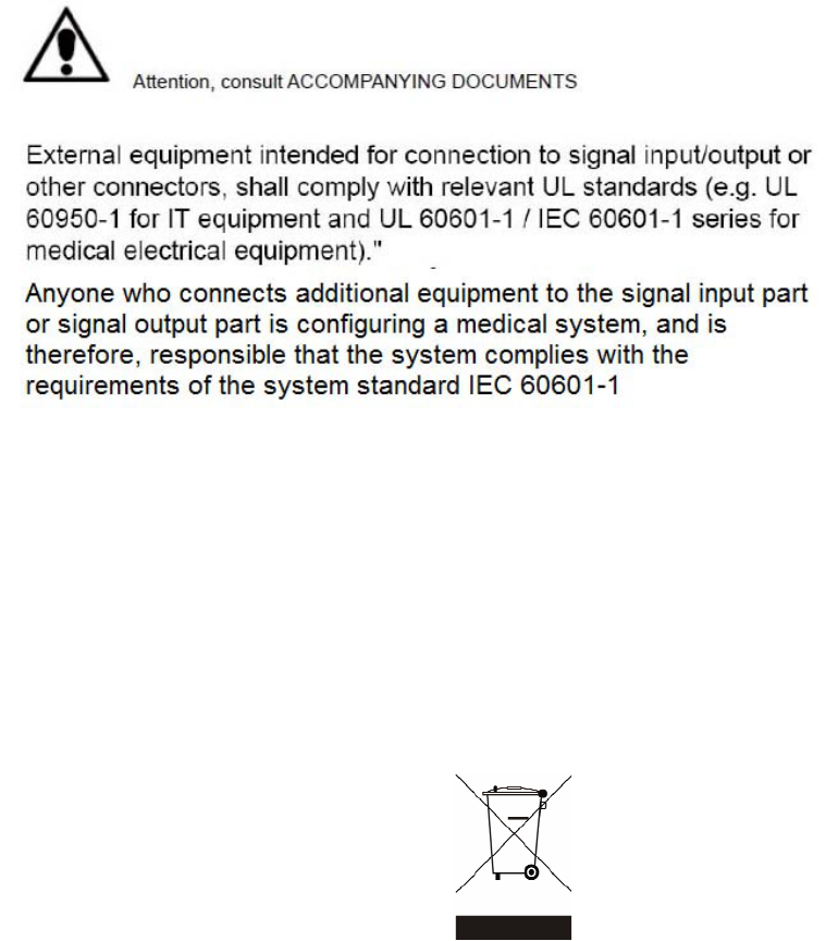
LEGISLATION AND WEEE SYMBOL
2012/19/EU Waste Electrical and Electronic Equipment Directive on the treatment,
collection, recycling and disposal of electric and electronic devices and their
components.
The crossed dustbin symbol on the device means that it should not be disposed of
with other wastes at the end of its working life. Instead, the device should be taken
to the waste collection centers for activation of the treatment, collection, recycling
and disposal procedure.
To prevent possible harm to the environment or human health from uncontrolled
waste disposal, please separate this from other types of wastes and recycle it
responsibly to promote the sustainable reuse of material resources.
Users should contact either the retailer where they purchased this product, or their
local government office, for details of where and how they can take this item for
environmentally safe recycling.
Business users should contact their supplier and check the terms and conditions of
the purchase contract.
This product should not be mixed with other commercial wastes for disposal.

Troubleshooting
For your own safety and that of your equipment, always take the following precautions.
Disconnect the power plug (by pulling the plug, not the cord), from your computer if
any of the following conditions exists:
The power cord or plug becomes frayed or otherwise damaged.
You spill something into the case.
Your computer has been dropped or the case has been otherwise damaged.
You suspect that your computer needs service or repair.
You want to clean the computer or screen.
You want to remove/install any parts.
Repair of the device may only be carried out by trained service personnel.
We recommend that a service contract be obtained with supplier and
that all repairs also be carried out by them. Otherwise the correct
functioning of the device may be compromised.
Please read the user manual

Revision History
Revision Date Description
V1.0 June, 2011 Release
V1.1 August, 2014
Remove C43 motherboard
Add C73 motherboard
Replace MSR module with 2nd smart IC
card reader
Table Content
1 Intended Use ........................................... 2
2 Item Checklist ......................................... 3
2-1 Standard Items .................................................................. 3
3 System View ............................................ 4
3-1 Front View & Side View ...................................................... 4
3-2 Rear View ........................................................................... 5
3-3 I/O View .............................................................................. 6
3-4 Indicator Lights .................................................................. 7
4 Driver Installation ................................... 8
4-1 Driver List ........................................................................... 8
4-2 Chipset Driver Installation ................................................. 9
4-3 VGA Driver Installation .................................................... 10
4-4 Audio Driver Installation .................................................. 13
4-5 10/100/1000Mb LAN Driver Installation ...................... 14
4-6 POSTouch Driver Installation .......................................... 15
5 System Assembly ................................. 18
5-1 HDD Replacement ........................................................... 18
5-2 Stand Assembly ............................................................... 18
6 Peripheral Installation ......................... 19
6-1 Phone Set Installation ..................................................... 19
6-2 2nd Smart IC Card Reader Installation ........................... 19
7 Specification ........................................ 20
8 Jumper Setting ..................................... 22
8-1 C73 Motherboard Layout ................................................ 22
8-2 Connectors & Functions .................................................. 23
8-3 Jumper Setting ................................................................. 25
Appendix: Driver Installation .................. 27

2
1 Intended Use
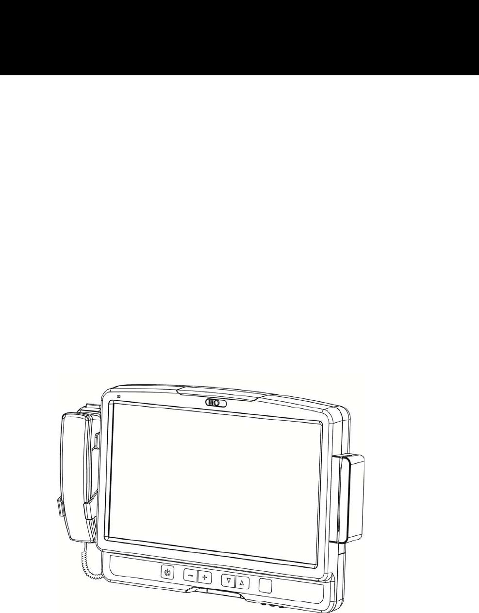
According to the Instructions for Use (IFU) of the manufacturer, the Bedside Terminal
has the following intended use:
The Bedside Terminal Hardware System is a computing device capable of storing,
retrieving and sending data electronically. This Bedside Terminal Hardware System,
including its user interface, battery, PCB and power supply, is intended to be fixed to a
stand in medical care environment. This Bedside Terminal Hardware System must be
operated by professional personnel.
3
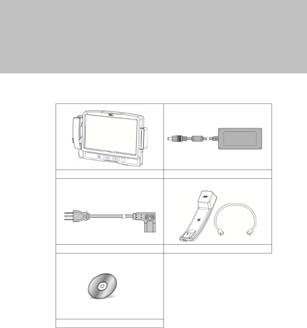
2 Item Checklist
2-1 Standard Items
a. System b. Power adapter (60W)
c. Power cable d. Phone module
e. Driver CD
4
3 System View
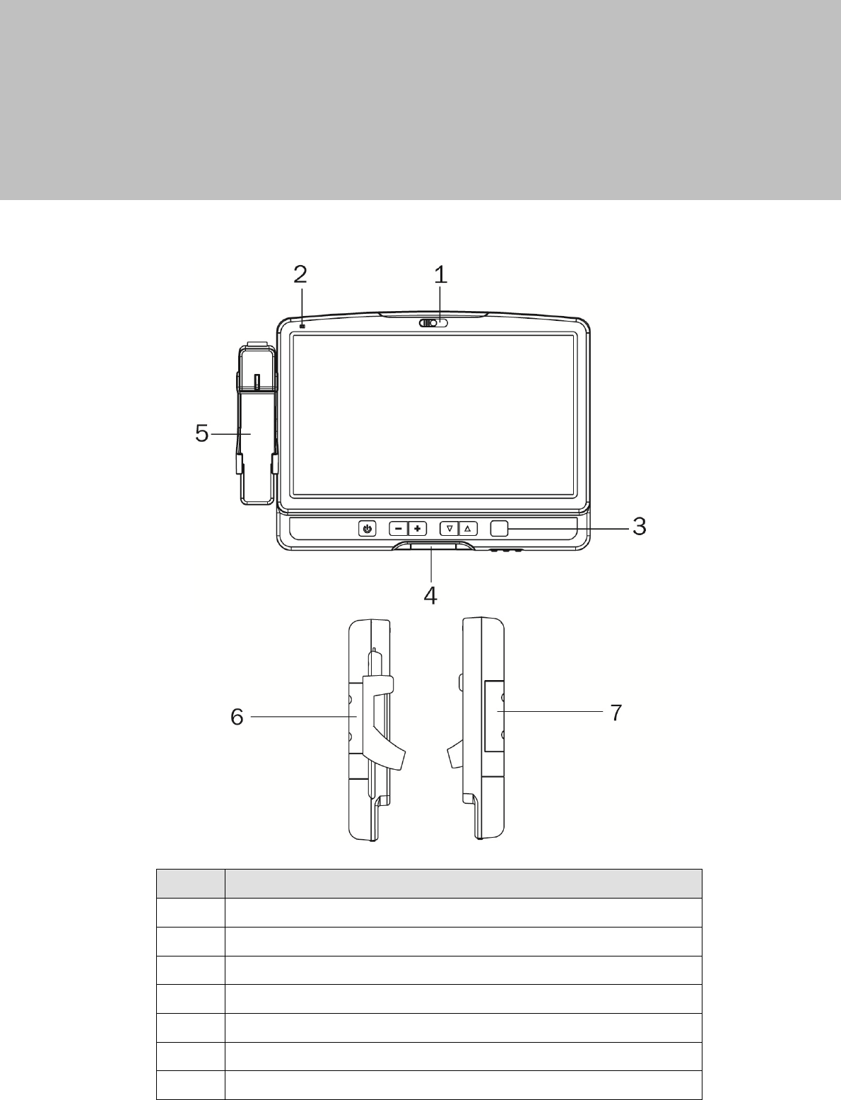
3-1 Front View & Side View
No. Description
1 Build-in camera
2 Build-in microphone
3 Key pad (power, volume button)
4 Smart card reader slot
5 Phone
6 Phone holder
7 2nd smart card reader dummy cover
5
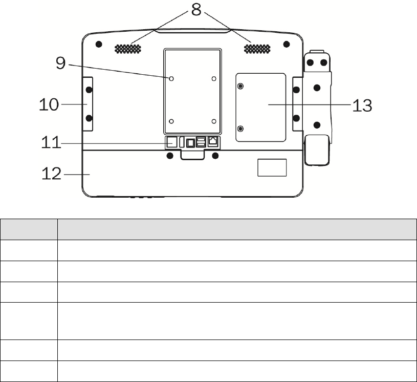
3-2 Rear View
No. Description
8 Speakers
9 VESA holes x 4
10 2nd smart card reader dummy cover
11 Rear I/O
(from right to left: RJ48, USBx2, DC-IN, Display port , LAN)
12 Cable cover
13 HDD door
6
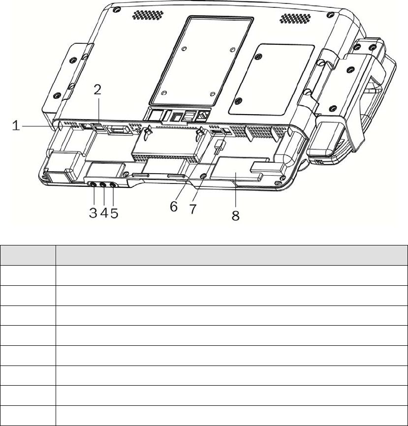
3-3 I/O View
No. Description
1 LAN (RJ45)
2 USB x 2
3 USB x 1
4 Phone Jack (RJ11)
5 Audio Line-out
6 Audio Line-in
7 Audio MIC-IN
8 RFID sensor
7
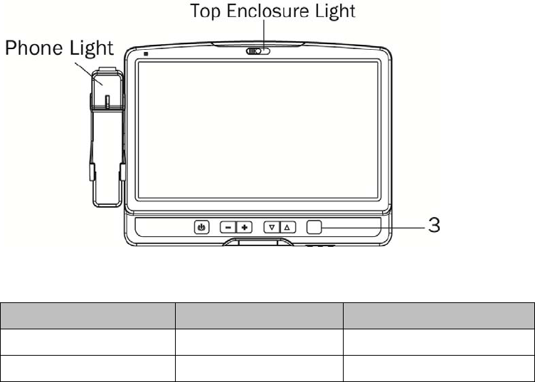
3-4 Indicator Lights
Light LED Color Status
Top enclosure light blue ornament light
Phone light blue phone rings
Symbols on Label and abbreviations on this equipment (from left to right):
Power on/off
Volume down
Volume up
Channel down
Channel up

8
4 Driver Installation
4-1 Driver List
Folder/File File Description
<CD>:\ K936_C73.htm Driver List
<CD>:\COMMON\INTEL\Chipset\i9xx Chipset Driver
<CD>:\COMMON\INTEL\VGA\GMA3150 VGA Driver
<CD>:\COMMON\Audio\Realtek_HD_Codec-AEC_enable
Audio driver with AEC enable
<CD>:\COMMON\ POS_Touch POSTouch Driver
<CD>:\COMMON\Lan_driver\Intel 10/100/1000Mb LAN Driver
-The following procedures are for Windows 2000/XP, other platforms are similar.
9
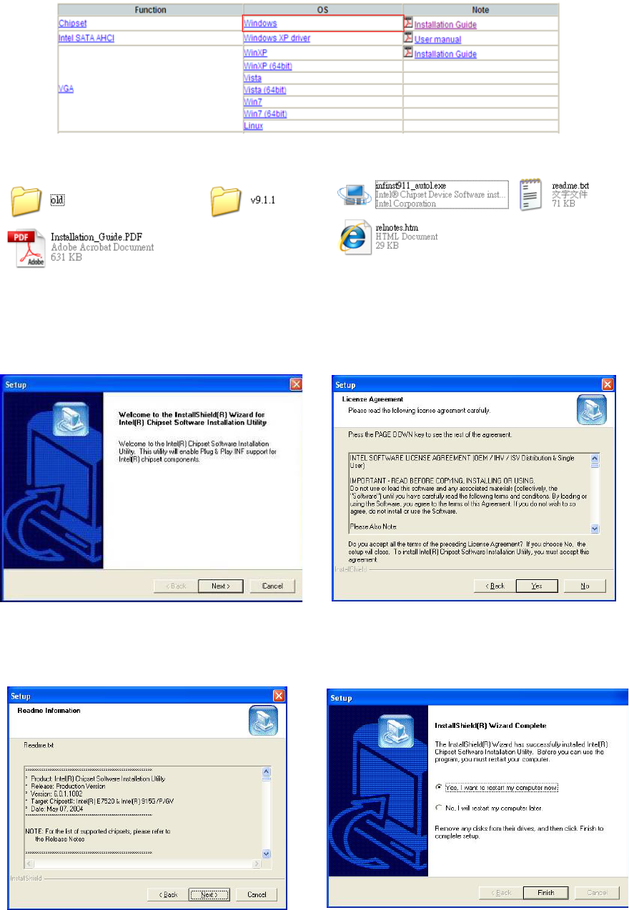
4-2 Chipset Driver Installation
a. Click “Windows” in the Driver List menu of K936 C43 and then doule-click “v9.1.1”
b. Double-click “infinsts911_autol.exe” on the My computer window.
c. Click the “Next” button on the Welcome
window.
d. Click the “Yes” button on the License
Agreement window.
e. Click the ”Next” button on the Readme
Information window.
f. Click the “Finish” button and restart your
system.
10
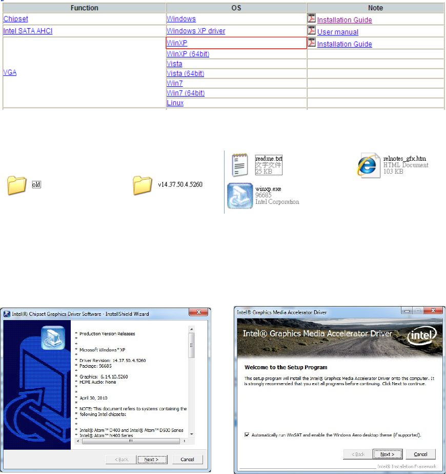
4-3 VGA Driver Installation
a. Click “WinXP” of “VGA” section in the Driver List menu and then double-click
“v14.37.50.4.5260”
b. Double-click “winxp.exe” on the My computer window..
c. Click the “Next” button on the Intel(R)
Chipset Graphics Driver Software- Install
Shield(R) Wizard dialog.
d. Click the “Next” button on the Intel(R)
Graphics Media Accelerator Driver dialog.
11
e. Click the “Yes” button on the Intel(R)
Graphics Media Accelerator Driver dialog.
f. Click “Next” button on the Intel(R)
Graphics Media Accelerator Driver dialog.
g. Click “Next” button on the Intel(R)
Graphics Media Accelerator Driver dialog.
h. Select
“Yes, I want to restart m
y
computer now” and click the “Finish”
button on the Intel(R) Graphics Media
Accelerator Driver dialog.
12
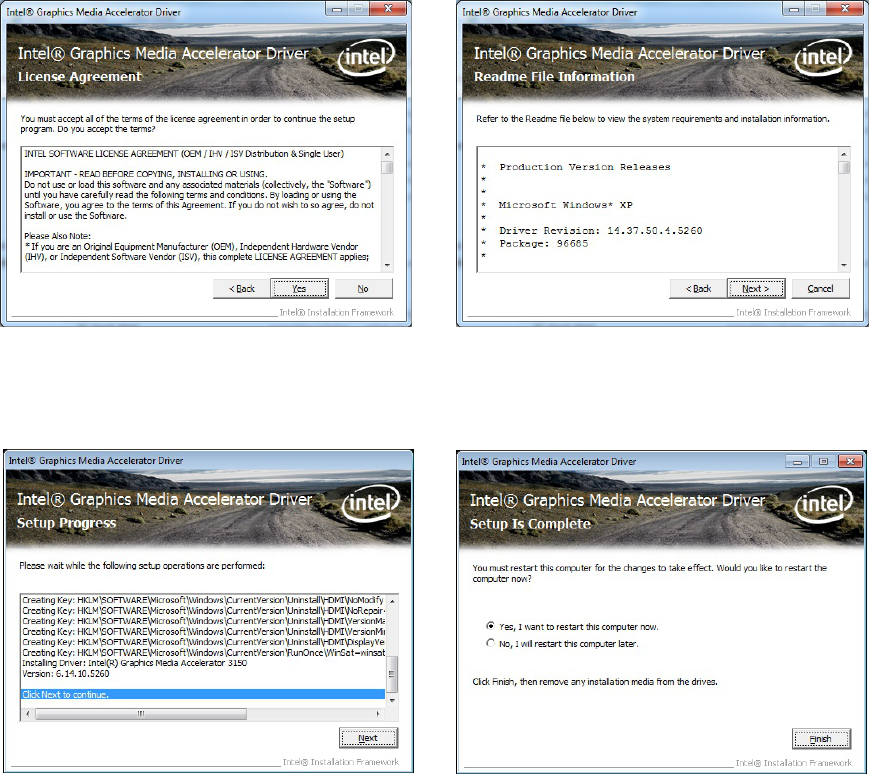
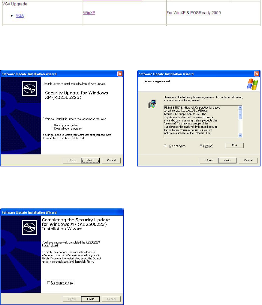
For WinXP and POSReady 2009 upgrade
a. Click “WinXP” of “VGA” section in the Driver List menu.
b. Click the “Next” button on the Software
Update Installation Wizard dialog.
c. Click “I Agree” and click “Next” button
on the Software Update Installation
Wizard dialog.
d. Click
t
he “Finish” button on the
Software Update Installation Wizard
dialog to restart your system.
13
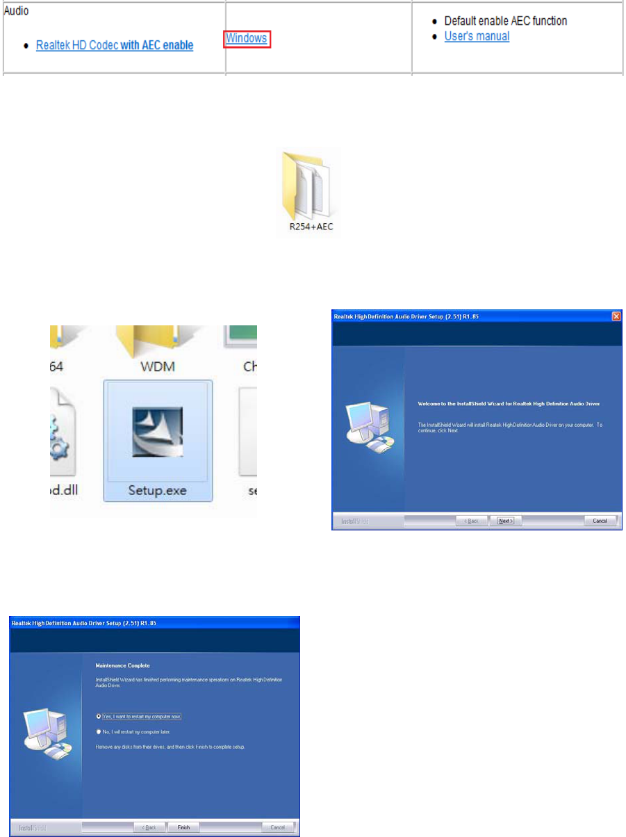
4-4 Audio Driver Installation
a. Click “Windows” of the “Audio” section in the Driver List menu.
b. Double-click R254+AEC” on the My Computer window.
c. Double-click “Setup.exe” on the My
Computer window.
d. Click “Next” button on the Realtek
Audio Setup window.
e. Click “Finish” button on the Realtek
Audio Setup window.
14
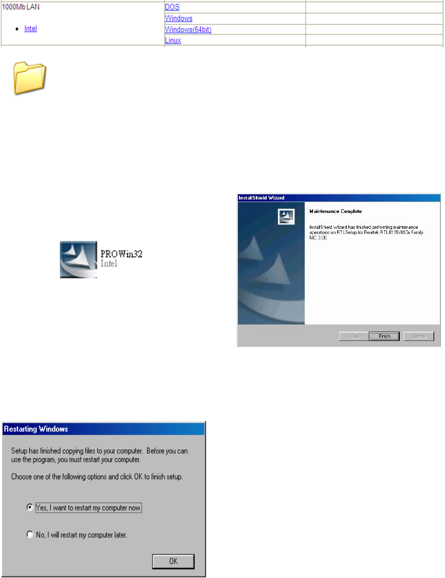
4-5 10/100/1000Mb LAN Driver Installation
a. In the “intel” section, click on “Windows” and click on “Alpha”
b. Double-click “v15.6”
c. Double-click Setup.exe
d. Click the Finish button on the
Maintenance Complete window.
e. Click the OK button and restart your
system.
v15.6
15
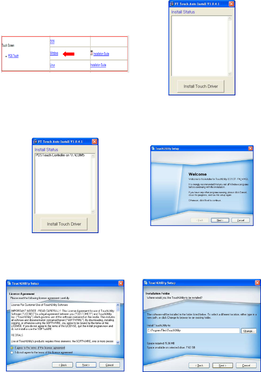
4-6 POSTouch Driver Installation
a. In the “Touch Screen auto…”
section,
click “Windows”.
b. Click “Install Touch Driver” on “FT Touch
Auto Install V1.0.4.1” window to detect
the touch type in your system.
c. “FT Touch Auto Install” program will
detect what touch type and interface
being installed on the system.
d. Click ”Next”.
e. Select ”I agree…” and click ”Next”.
f. Select the installation folder for the
touch utility driver and click ”Next”.
16
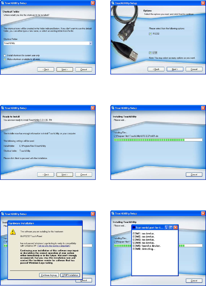
g. Select the shortcut folder for the touch
utility driver and click ”Next”.
h. Click ”Next”.
i. Click ”Next”.
j
. The computer is installing the touch
driver
k. Click ”Continue Anywa
y
” button.
l. The serial ports are scanned for a touch
device. The Touch panel is on COM5.
17
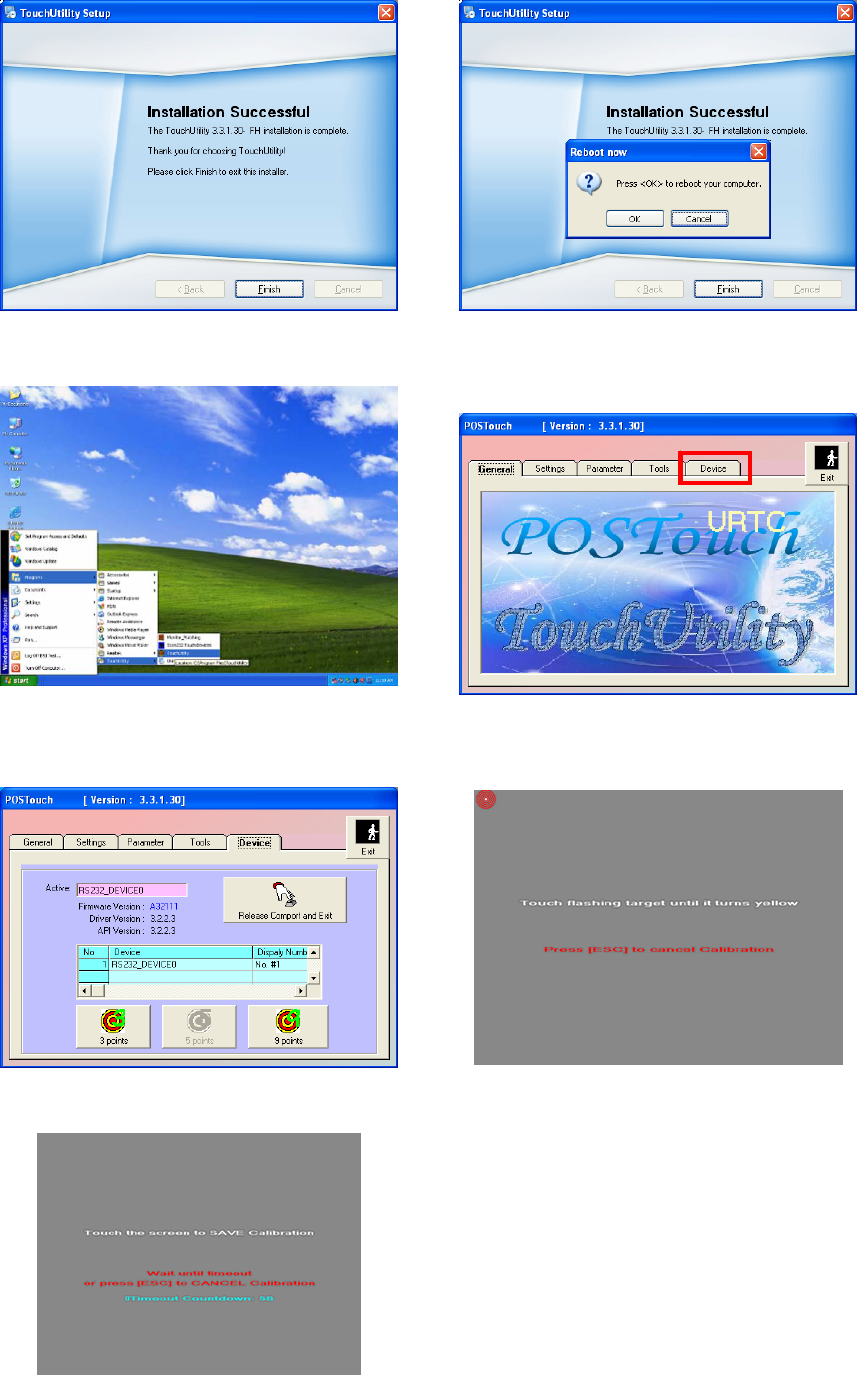
m. Click ”Finish”. n. Click ”OK”
t
o restart the computer and
finish the touch utility installation.
o. The computer has restarted. Click on
the ”Start” button, select “Programs”,
t
hen select ”Touchutilit
y
”.
p. Select the Device tab.
q. Click on the 3 points or the 9 points
calibration button.
r. Follow the instructions on the screen to
do the calibration of the touch panel.
Touch anywhere on the screen to save the calibration.
18
5 System Assembly
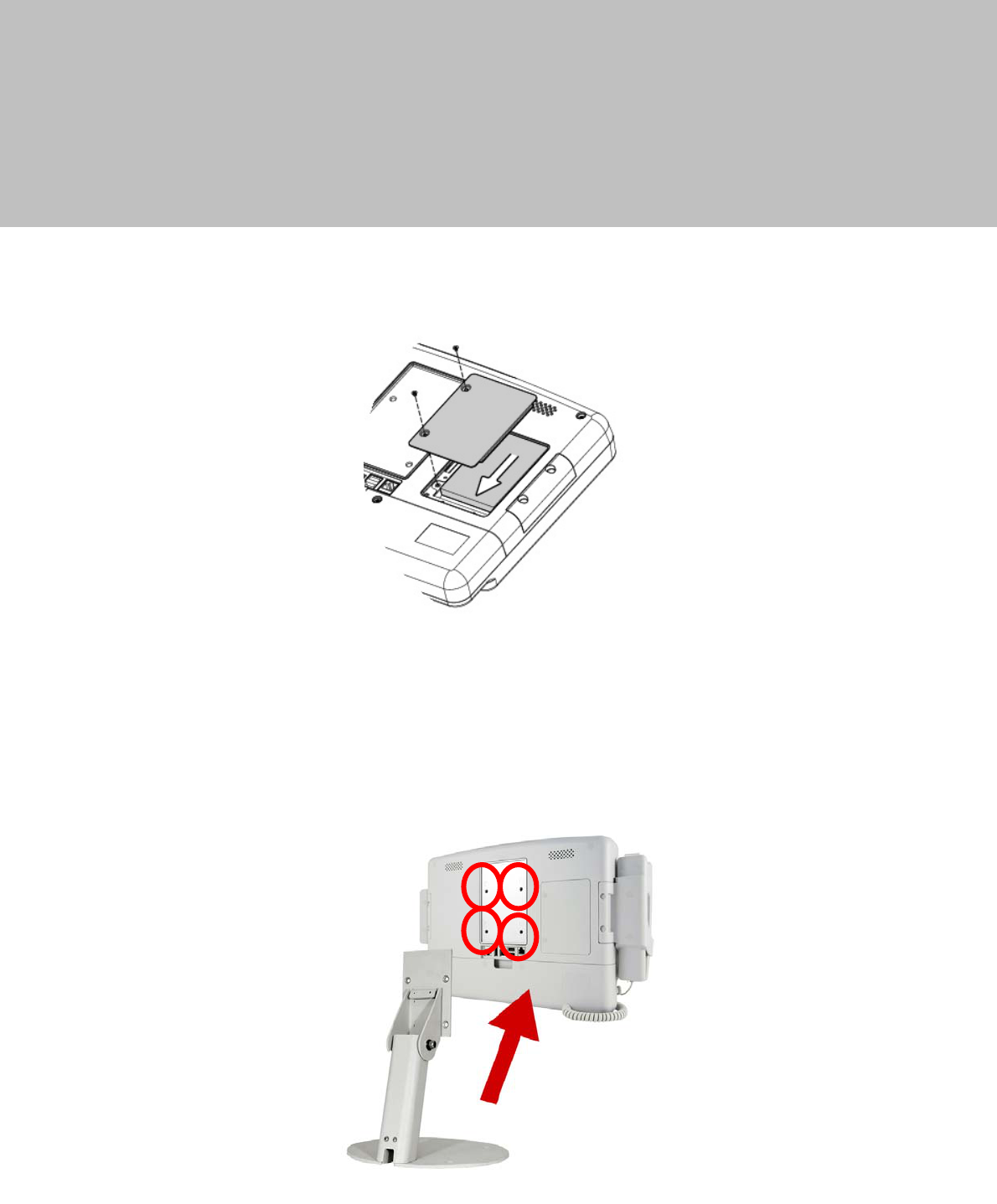
5-1 HDD Replacement
1. Find the HDD door at the rear right side of the system and loosen the screws(x2).
2. To replace the HDD, push the HDD outwards as picture shown.
5-2 Stand Assembly
1. To install the stand, attached the stand module to the rear of the system and
fasten the screws (x4) to secure the stand to the system.
19
6 Peripheral Installation
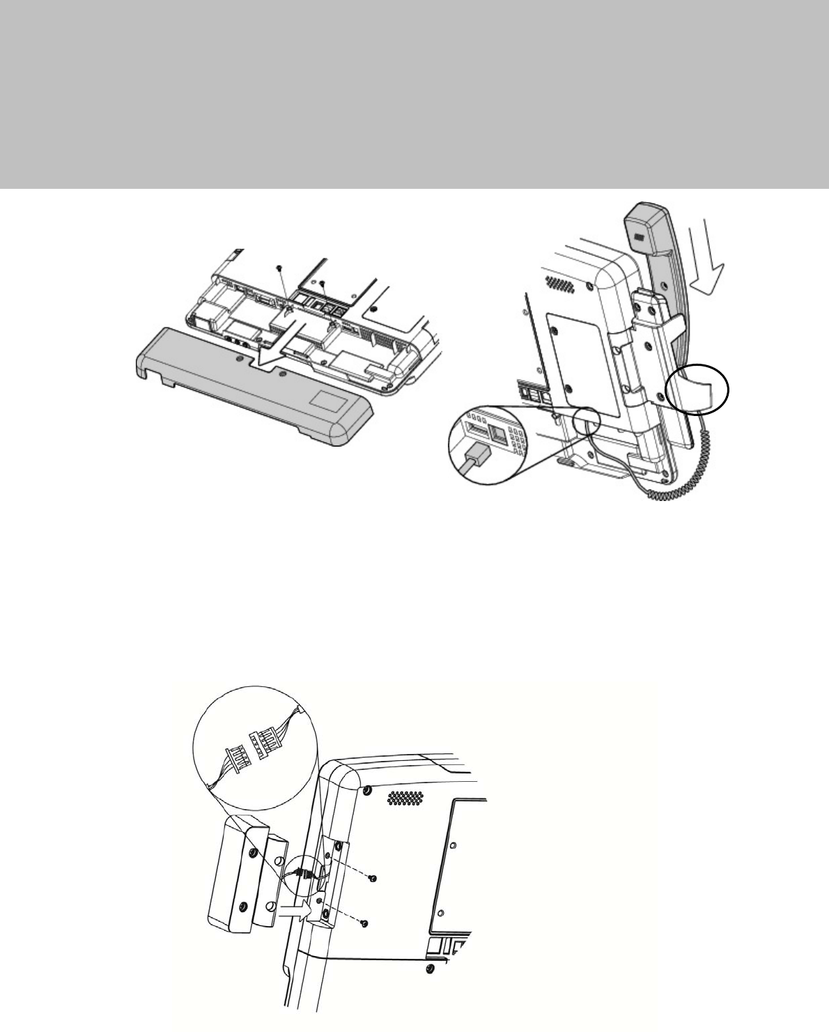
6-1 Phone Set Installation
1. Loosen the screws(x2) to open the cable cover.
2. Slide the phone module into the phone set holder and connect the phone
cable to the connector on the phone module.
3. Connect the other end of the phone cable to the connector on the system.
6-2 2nd Smart IC Card Reader Installation
1. Connect the cable to connector to the on system side.
2. Fasten screws(x2) to secure the module.

20
7 Specification
Model K936
Motherboard C73
Processor Intel® Ivy Bridge CPU, BGA, 22nm
Celeron 1047UE 1.4G, LLC 2M, 17W
Core logic HM76
System memory 2 x DDR3 SO-DIMM slot up to 8GB FSB 1333/1600Mhz
Graphic memory DX11, HD Graphics, 350MHz
LAN controller / PHY Intel WG82583V / Intel WG82579V
Audio controller Realtek ALC 662-GR HD codec
I/O controller Winbond W83627UHG
Watch dog timer Hardware WDT
Cooling Fanless
DC-in 12V ~ 48V (wide range)
LCD Touch Panel
LCD size 15.6" LED LCD
Resolution 1366 x 768
Brightness 220 nits
Touch screen 5-Wire Resistive
Storage
Hard drive 1 x 2.5" Slim SATA HDD or SSD
Expansion
Mini PCI-E 2 x Full size slot(2W each, total 4W)
Audio/Light sensor
Speaker 2 x 2W Built-in
External I/O
Line-out 2
Mic-in 1
USB 2.0 3
USB 3.0 2
LAN (10/100/1000) 2 x RJ45
Power button 1
Reset button 1
Display port 1 for DVI-D
COM 1 x RJ48

21
Model K936
Motherboard C73
Phone jack 1 x RJ11
Power
Power adaptor Medical Grade 12V/60W
Mechanism
Mounting 75x75mm VESA Standard
Special material Antibacterial Plastic Housing
Peripheral
Webcam 2M Pixel Camera & Camera Latch
VOIP phone 1 x Handset & Cradle
Smart IC card reader 1
RFID 1
2nd Smart IC card reader Optional
Scanner 1 x 2D Optional Scanner
Certificate
EMC & Safety FCC / CE / EN60601-1-2 / UL60601-1 3rd/ANSI/AAMI ES60601-1
Environment for System
Operation temperature 0°C ~ 35°C (32°F ~ 95°F)
Storage temperature -20° ~ 60°C (-4°F ~ 140°F)
Storage humidity 30% ~ 93% RH Non-condensing
Atmospheric pressure range 700 - 1060 hPa
Dimension/Weight
Dimension 390 x 55 x 297 mm (15.4" x 2.2" x 11.7")
Weight 4kgs w/o Handset & Cradle
* This specification is subject to change without prior notice.
Application: Access to patient records / Hospital administration system / Bed management
Manufactory information:
Factory: Flytech Technology Co., Ltd.
Address: NO.36 Huaya 3rd Rd., Guishan Township, Taoyuan County 33383, Taiwan
Tel No: 886-3-272-9688 Fax No: 886-3-272-9666
Note: Cleaning solution-Wipe with cloth using clean water, 2 times a week.
Adaptor Manufacturer: FSP TECHNOLOGY INC.
Model: PMP60-12-B16
Rating: 100-240V,47-63Hz,1.22-0.68A
22
8 Jumper Setting
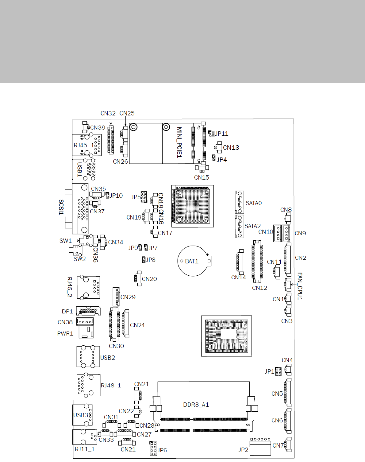
8-1 C73 Motherboard Layout

23
8-2 Connectors & Functions
Connector Function
CN3 USB Port For Web Cam
CN4 Speaker & MIC
CN5 Cradle
CN6 Speaker
CN7 Audio Jack (Line out & MIC)
CN9 Inverter
CN10 Build-In MIC
CN14 Membrane
CN15 30P All-In-One
(Membrane, 2D scanner, RFID, Smart card, Audio Jack)
CN18 Audio Jack (Line Out)
CN19/JP5 System Indicator
CN20 IrDA
CN21 LVDS
CN22 Power LED
CN23 PS/2 Keyboard
CN24 MSR
CN25 COM1
CN26 System FAN
CN27 MIC for AEC
CN28 Power Button
CN29/30 SATA Power
CN31 HDD LED
CN32/35 Internal USB
CN33 USB Port For DVD Dong
CN34 LAN2 LED
CN36 Battery
CN37 USB Port For RFID
CN38 2D Scanner
CN39 USB Port For Smart Card
CN40 LAN1 LED
DP3 DVI
PWR3 +19V DC Jack
RJ11_3 Handset
RJ45_3 LAN2
RJ45_4 LAN1
RJ48_1 COM
SATA1/2 SATA
USB3 USB3

24
Connector Function
JP3 Touch
JP4 Inverter Selection
JP6 LCD ID Setting
JP7 MCU Power Button
JP8 Power Mode Setting
JP9 MCU Mode Setting
JP10 System Reset
JP11 CMOS Operation Mode
25
8-3 Jumper Setting
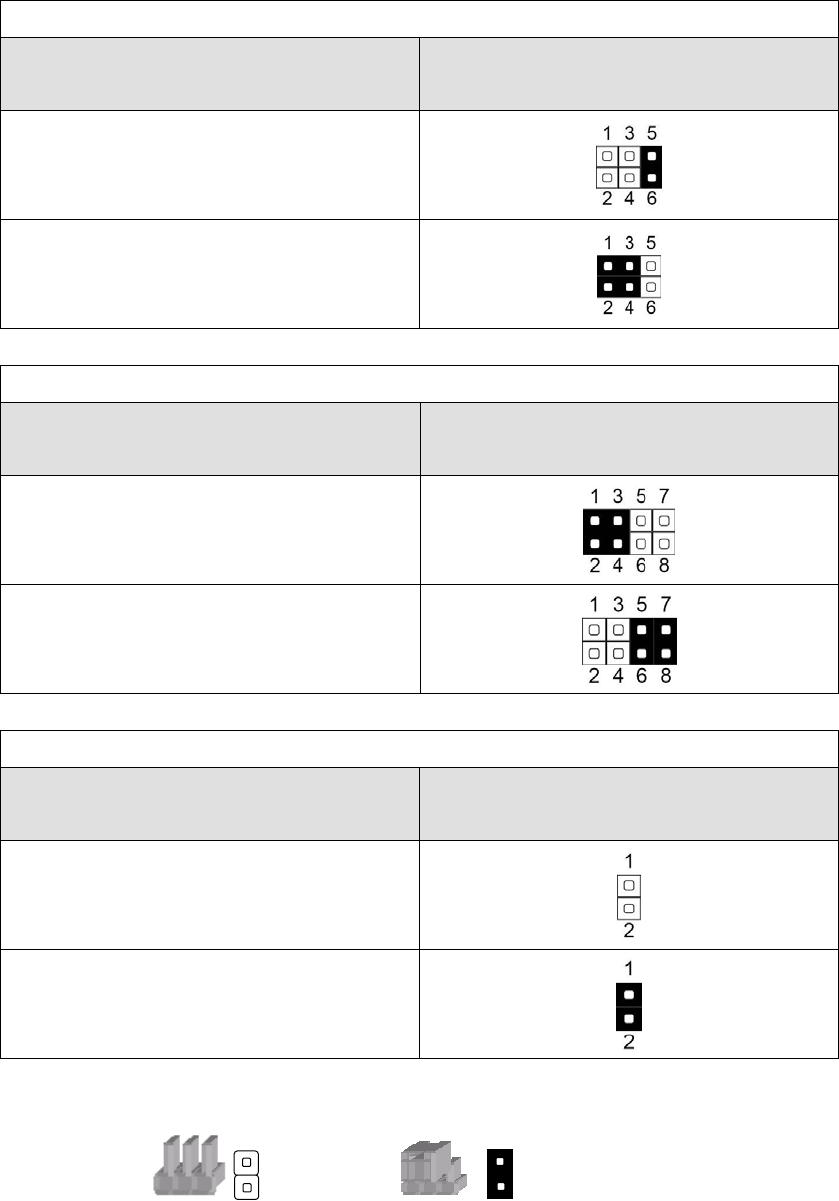
Inverter Selection
Function JP4
(1-2) (3-4) (5-6)
▲CCFL
LED
System Indicator
Function JP5
(1-2) (3-4) (5-6) (7-8)
▲Disable
Enable
MCU Power Button
Function JP7
(1-2)
Disable
▲Enable
▲ = Manufacturer Default Setting
Note:
OPEN SHORT
26
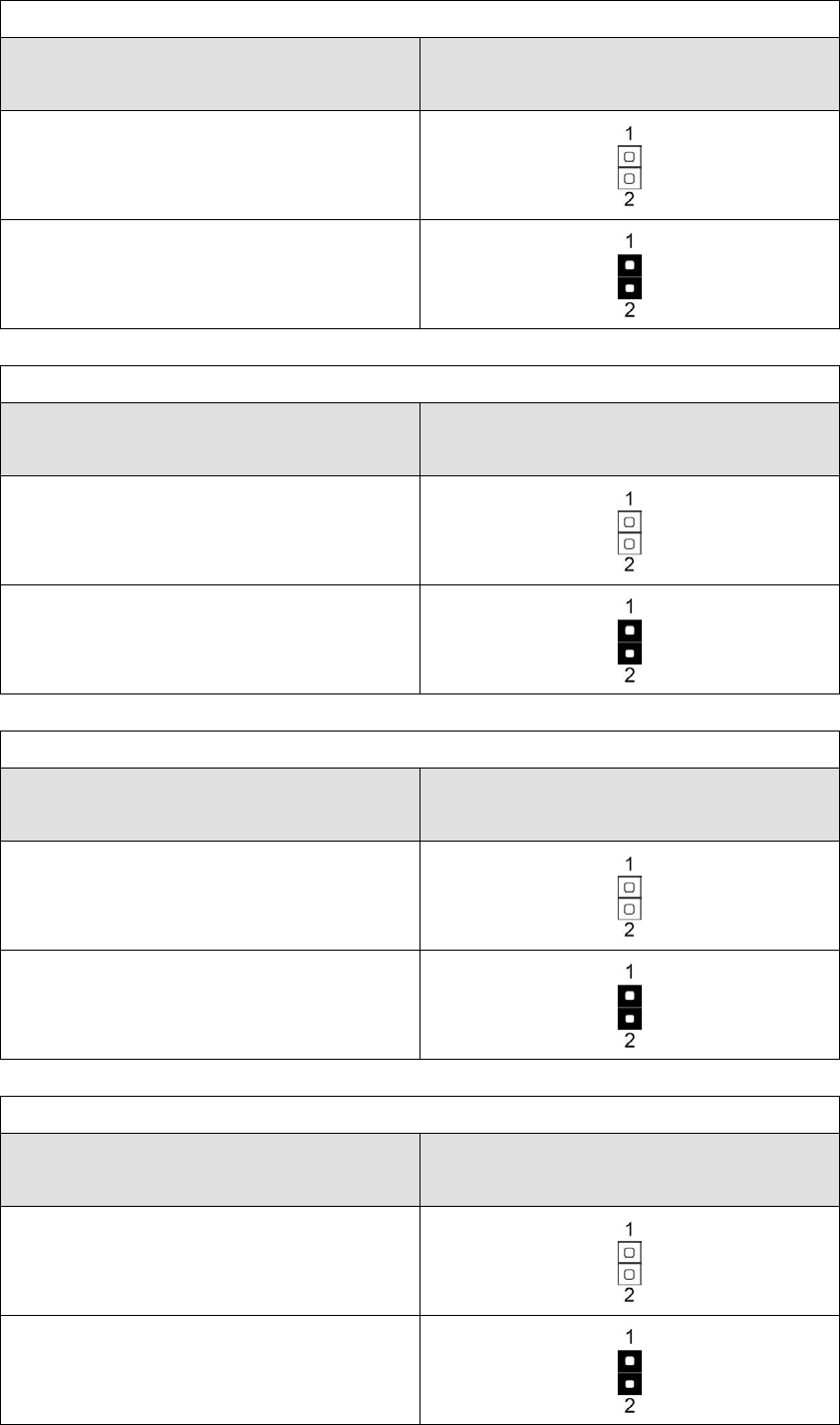
Power Mode Setting
Function JP8
(1-2)
ATX Power
▲AT Power
MCU Mode Setting
Function JP9
(1-2)
▲Normal
ISP Debug
System Reset
Function JP10
(1-2)
▲System Normal
System Reset
CMOS Operation Mode
Function JP11
(1-2)
▲CMOS Normal
CMOS Reset

27
Appendix: Driver Installation
The shipping package includes a Driver CD. You can find every individual driver and
utility that enables you to install the drivers in the Driver CD.
Please insert the Driver CD into the drive and double click on the “index.htm” to
pick the models. You can refer to the drivers installation guide for each driver in the
“Driver/Manual List”.