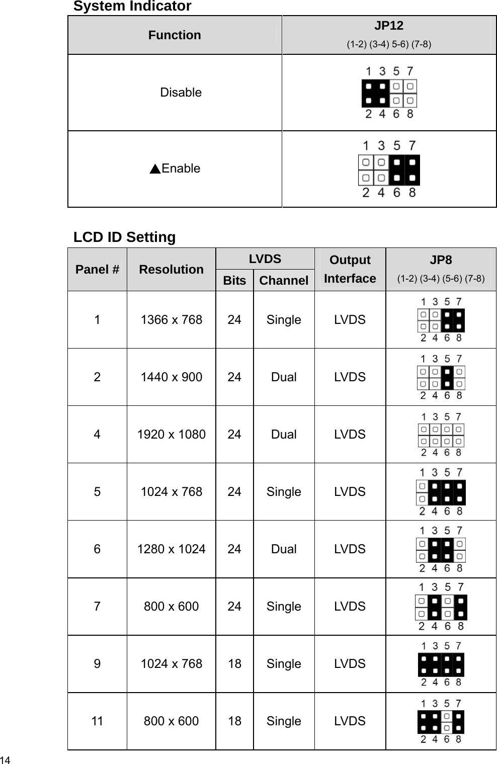
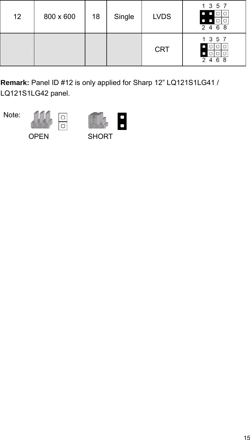
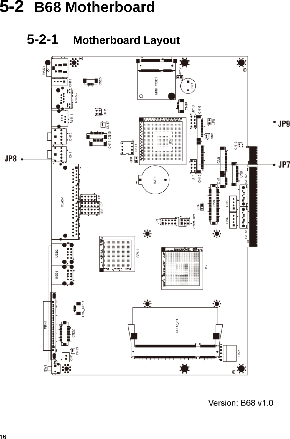
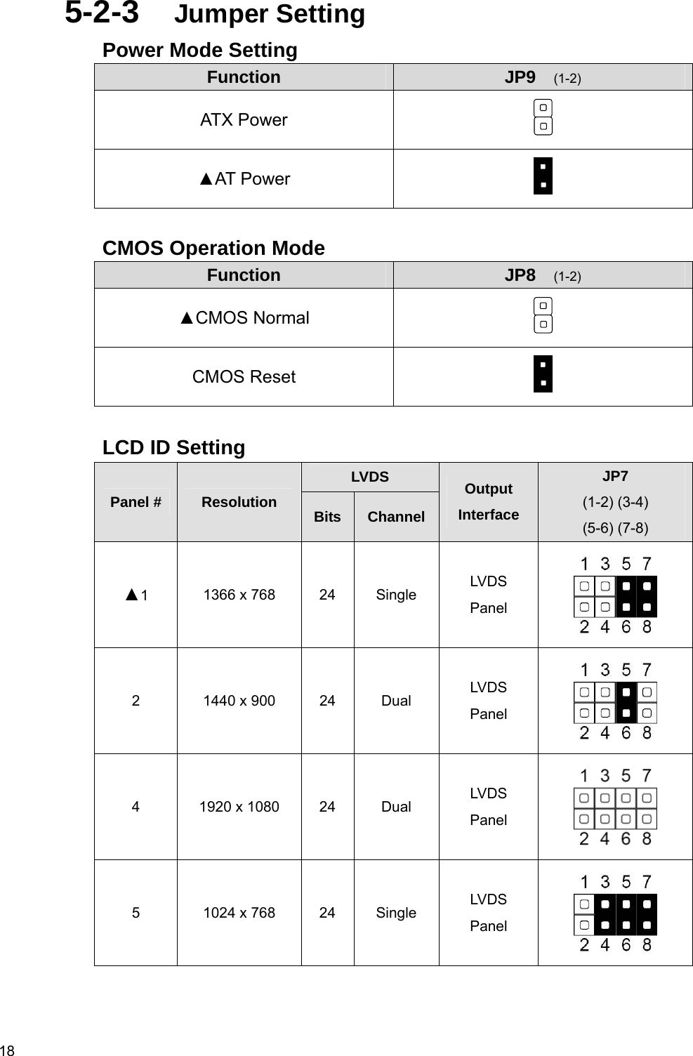
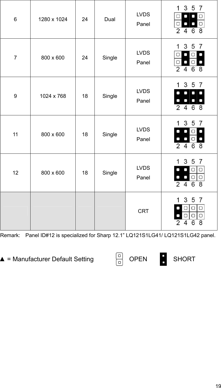
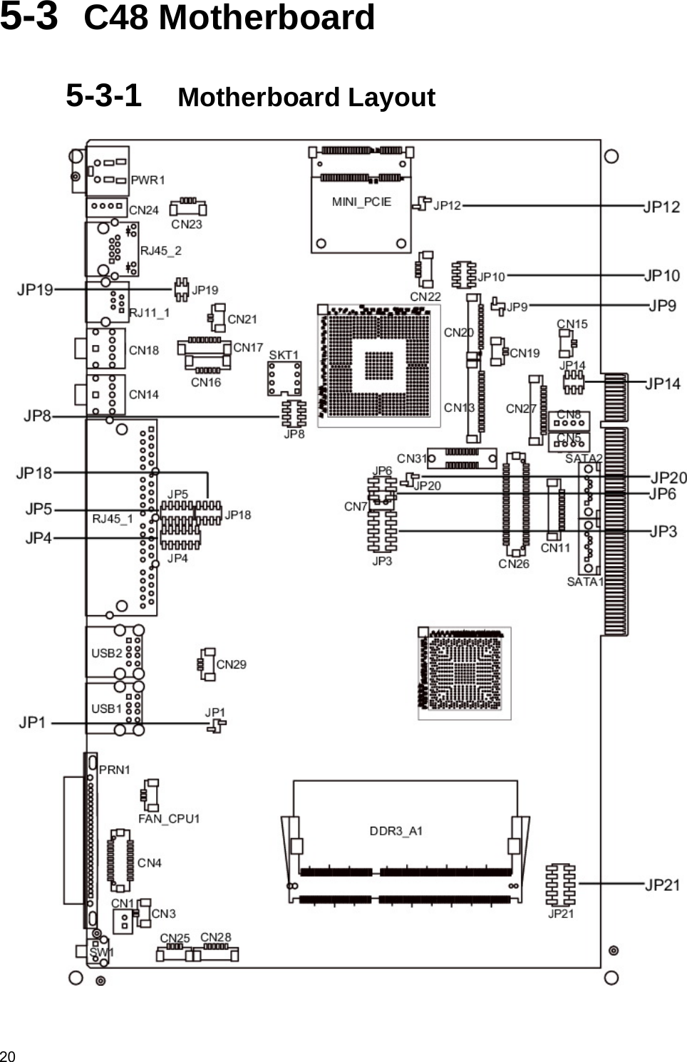
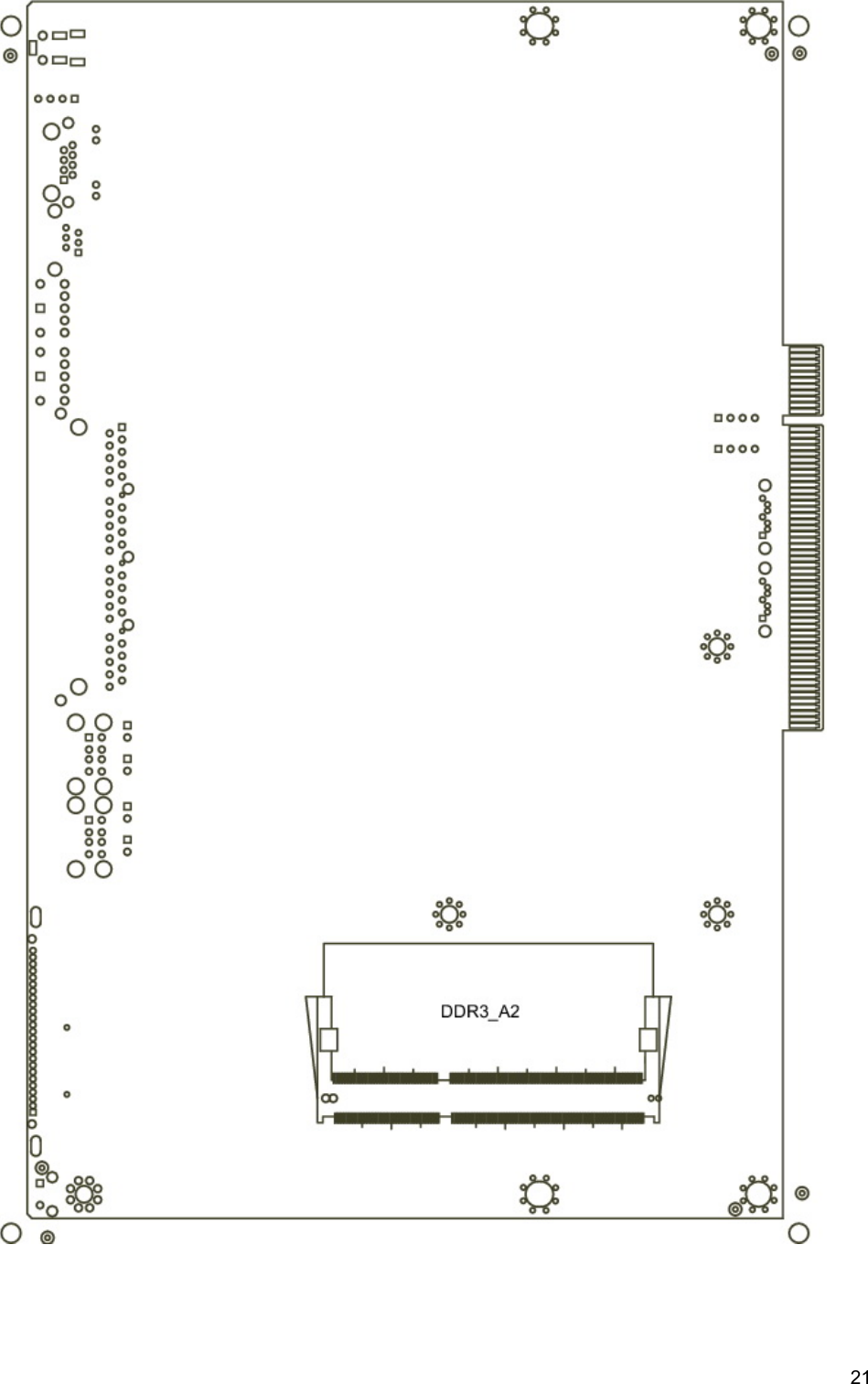
FLYTECH TECHNOLOGY K938C48 Bedside Terminal Hardware System User Manual K938 V1 4 avin
FLYTECH TECHNOLOGY CO., LTD Bedside Terminal Hardware System K938 V1 4 avin
UserManual.wiki
>
FLYTECH TECHNOLOGY
>
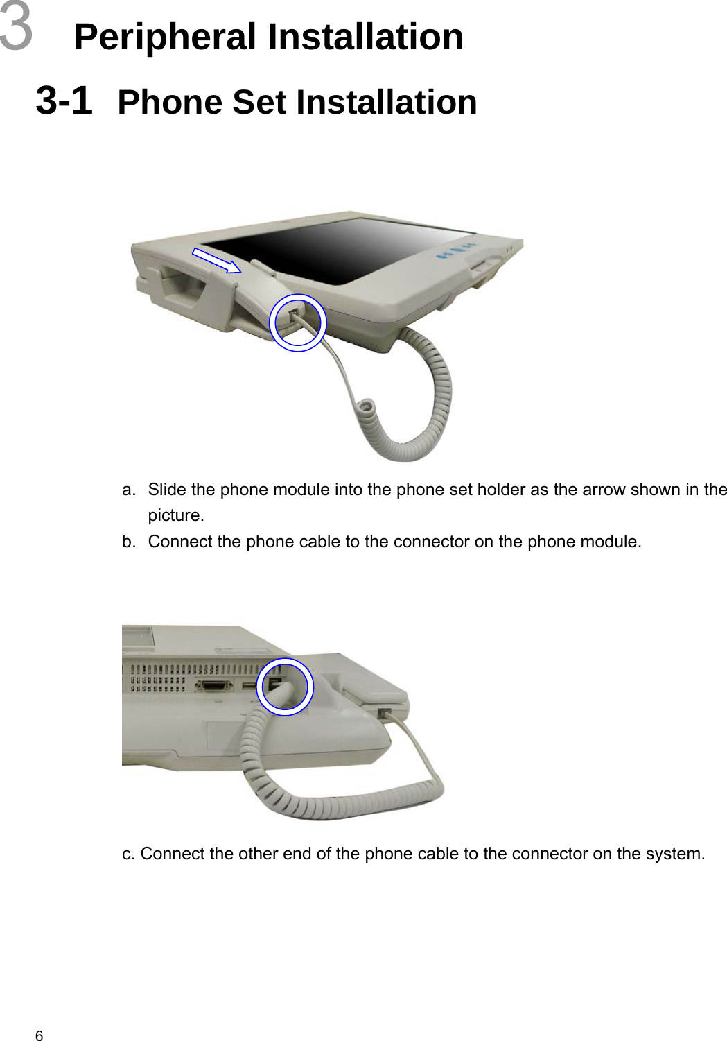
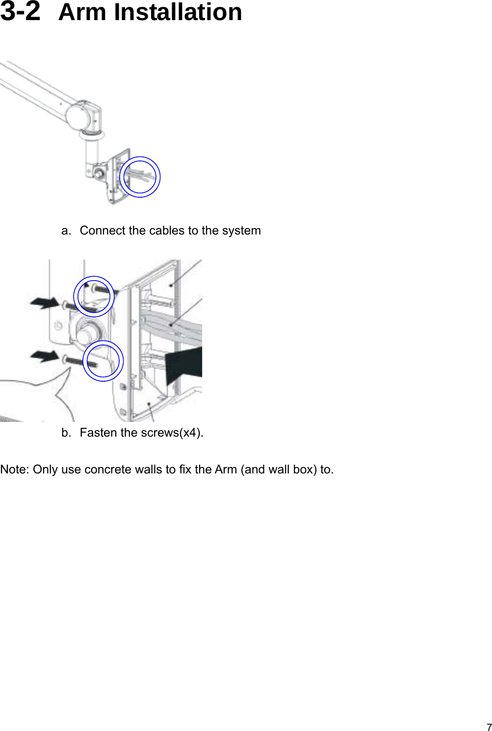
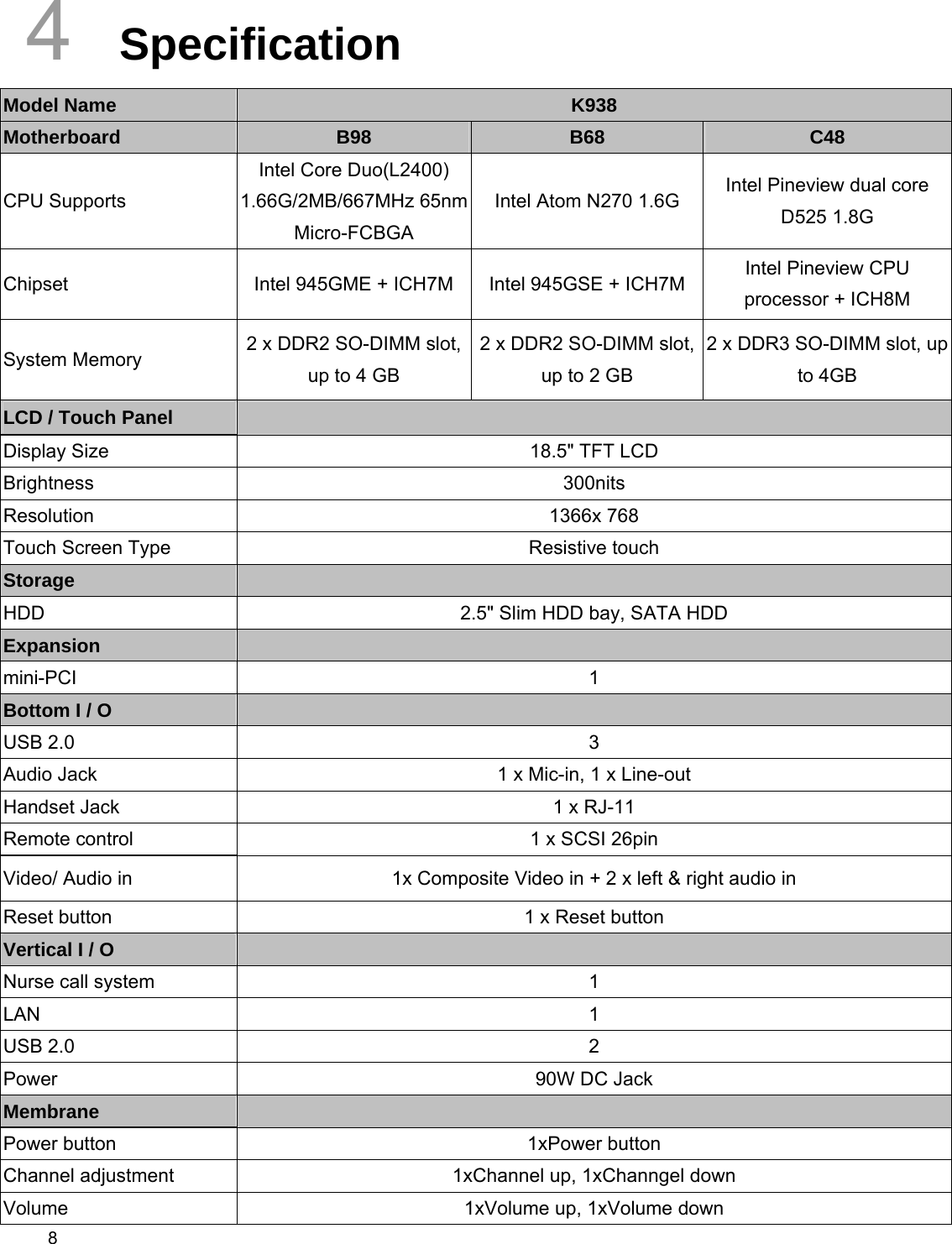
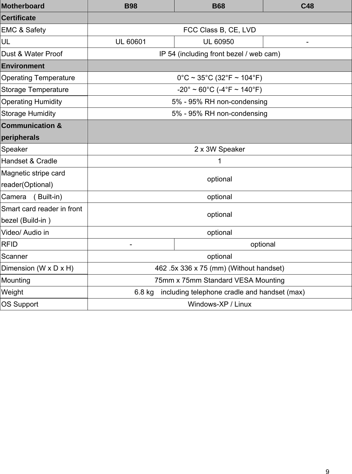
K938C48 User Manual
user manual
Navigation menu
Upload a User Manual
Namespaces
Wiki Guide
HTML
PDF
Info
Views
User Manual
Discussion / Help
Navigation