FLYTECH TECHNOLOGY K948C73 Bedside Terminal Hardware System User Manual R13 K948 C73 v1 0
FLYTECH TECHNOLOGY CO., LTD Bedside Terminal Hardware System R13 K948 C73 v1 0
User manual
Version 1.0 August 2013
Bedside Terminal
Hardware System
User Manual
i
Copyright 2013
All Rights Reserved
Manual Version 1.0
The information contained in this document is subject to change without notice.
We make no warranty of any kind with regard to this material, including, but not
limited to, the implied warranties of merchantability and fitness for a particular
purpose. We shall not be liable for errors contained herein or for incidental or
consequential damages in connection with the furnishing, performance, or use of
this material.
This document contains proprietary information that is protected by copyright. All
rights are reserved. No part of this document may be photocopied, reproduced or
translated to another language without the prior written consent of the
manufacturer.
TRADEMARK
Intel®, Pentium® and MMX are registered trademarks of Intel® Corporation.
Microsoft® and Windows® are registered trademarks of Microsoft Corporation.
Other trademarks mentioned herein are the property of their respective owners.
Safety
IMPORTANT SAFETY INSTRUCTIONS
1. To disconnect the machine from the electrical Power Supply, turn off the power
switch and remove the power cord plug from the wall socket. The wall socket
must be easily accessible and in close proximity to the machine.
2. Read these instructions carefully. Save these instructions for future reference.
3. Follow all warnings and instructions marked on the product.
4. Do not use this product near water.
5. Do not place this product on an unstable cart, stand, or table. The product may
fall, causing serious damage to the product.
6. Slots and openings in the cabinet and the back or bottom are provided for
ventilation; to ensure reliable operation of the product and to protect it from
overheating. These openings must not be blocked or covered. The openings
should never be blocked by placing the product on a bed, sofa, rug, or other
similar surface. This product should never be placed near or over a radiator or
heat register, or in a built-in installation unless proper ventilation is provided.
7. This product should be operated from the type of power indicated on the
marking label. If you are not sure of the type of power available, consult your
dealer or local power company.
8. Do not allow anything to rest on the power cord. Do not locate this product
where persons will walk on the cord.
9. Never push objects of any kind into this product through cabinet slots as they
may touch dangerous voltage points or short out parts that could result in a fire
or electric shock. Never spill liquid of any kind on the product.

ii
CE MARK
This device complies with the requirements of the EEC directive 2004/108/EC
with regard to “Electromagnetic compatibility” and 2006/95/EC “Low Voltage
Directive”
FCC
This device complies with part 15 of the FCC rules. Operation is subject to the
following two conditions:
(1) This device may not cause harmful interference.
(2) This device must accept any interference received, including interference
that may cause undesired operation
"Changes or modifications not expressly approved by the party responsible for compliance
could void the user's authority to operate the equipment."
This equipment has been tested and found to comply with the limits for a Class
B digital device, pursuant to part 15 of the FCC Rules. These limits are designed
to provide reasonable protection against harmful interference in a residential
installation.
This equipment generates, uses and can radiate radio frequency energy and, if
not installed and used in accordance with the instructions, may cause harmful
interference to radio communications. However, there is no guarantee that
interference will not occur in a particular installation. If this equipment does
cause harmful interference to radio or television reception, which can be
determined
by turning the equipment off and on, the user is encouraged to try to correct the
interference by one or more of the following measures:
—Reorient or relocate the receiving antenna.
—Increase the separation between the equipment and receiver.
—Connect the equipment into an outlet on a circuit different from that to which the
receiver
is connected.
—Consult the dealer or an experienced radio/TV technician for help
Battery Caution
Risk of explosion if battery is replaced by an incorrectly type.
Dispose of used battery according to the local disposal instructions.
Indicating that replacement by inadequately trained personnel could result in a
hazard (such as excessive temperatures, fire, or explosion)
Lithium battery: CR2032
iii
Safety Caution
Note: To comply with IEC60950-1 Clause 2.5 (limited power sources, L.P.S) related
legislation, peripherals shall be 4.7.3.2 "Materials for fire enclosure" compliant.
4.7.3.2 Materials for fire enclosures
For MOVABLE EQUIPMENT having a total mass not exceeding
18kg.the material of a FIRE ENCLOSURE, in the thinnest significant
wall thickness used, shall be of V-1 CLASS MATERIAL or shall pass
the test of Clause A.2.
For MOVABLE EQUIPMENT having a total mass exceeding 18kg
and for all STATIONARY EQUIPMENT, the material of a FIRE
ENCLOSURE, in the thinnest significant wall thickness used, shall
be of 5VB CLASS MATERIAL or shall pass the test of Clause A.1
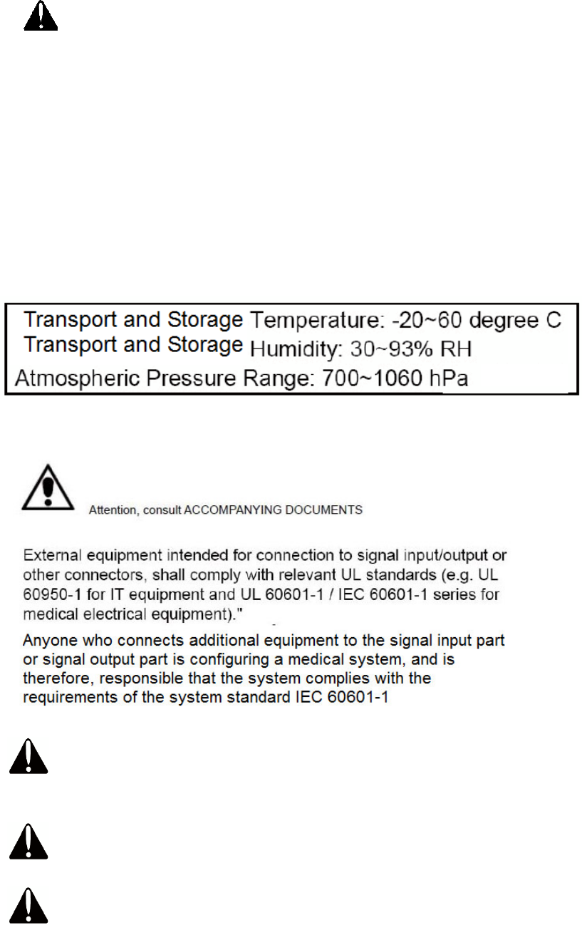
CAUTION SYMBOL IN CARTON
ATTENTION
WARNING:
To avoid risk of electric shock, this equipment must only be connected to a supply
mains with protective earth.
WARNING:
Do not modify this equipment without authorization of the manufacturer.
WARNING:
If an appliance coupler or separable plug is used as the disconnecting device, it shall
iv
be readily identifiable and easily reached by the operator. For single-phase portable
equipment, a plug on a cord of length not greater than 3m is considered to be easily
reached.
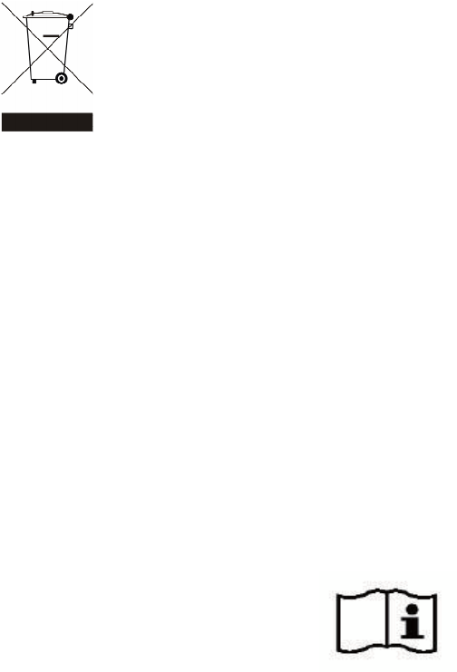
LEGISLATION AND WEEE SYMBOL
2012/19/EU Waste Electrical and Electronic Equipment Directive on the treatment,
collection, recycling and disposal of electric and electronic devices and their
components.
The crossed dustbin symbol on the device means that it should not be disposed of
with other household wastes at the end of its working life. Instead, the device
should be taken to the waste collection centers for activation of the treatment,
collection, recycling and disposal procedure.
To prevent possible harm to the environment or human health from uncontrolled
waste disposal, please separate this from other types of wastes and recycle it
responsibly to promote the sustainable reuse of material resources.
Household users should contact either the retailer where they purchased this
product, or their local government office, for details of where and how they can
take this item for environmentally safe recycling.
Business users should contact their supplier and check the terms and conditions
of the purchase contract.
This product should not be mixed with other commercial wastes for disposal.
Power supply is specified as a part of ME EQUIPMENT
Please read the user manual

v
Revision History
Revision Date Description
V1.0 August, 2013 Release
vi
Table of Contents
1 Intended Use ...................................................... 1
2 Package Checklist ............................................ 2
2-1 Standard Items ................................................................................. 2
3 System View ....................................................... 3
3-1 Front View .......................................................................................... 3
3-2 Side View............................................................................................ 4
3-3 Rear View ........................................................................................... 4
3-4 Bottom View ...................................................................................... 5
3-5 Dimension .......................................................................................... 5
4 System Assembly .............................................. 6
4-1 SSD/HDD Replacement .................................................................. 6
5 Peripherals Installation .................................... 7
5-1 Phone module Installation .............................................................. 7
5-2 Stand Installation ………………………………………………………………….8
6 Specification ...................................................... 9
7 Jumper Setting ................................................ 12
7-1 C73 Motherboard ........................................................................... 12
7-2 Connectors & Functions ................................................................ 13
7-3 Jumper Setting ................................................................................ 14

1
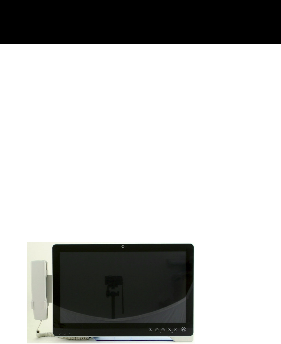
1 Intended Use
According to the Instructions for Use (IFU) of the manufacturer, the Bedside Terminal
has the following intended use:
The Bedside Terminal Hardware System is a computing device capable of storing,
retrieving and sending data electronically. This Bedside Terminal Hardware System,
including its user interface, battery, PCB and power supply, is intended to be fixed to a
stand in medical care environment.
2
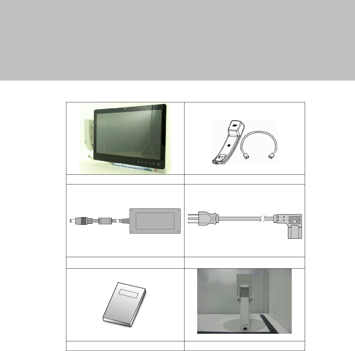
2 Package Checklist
2-1 Standard Items
a. System
b.
Phone module
c. Power adapter d. Power Cable
e. Manual f. Stand
3
3 System View
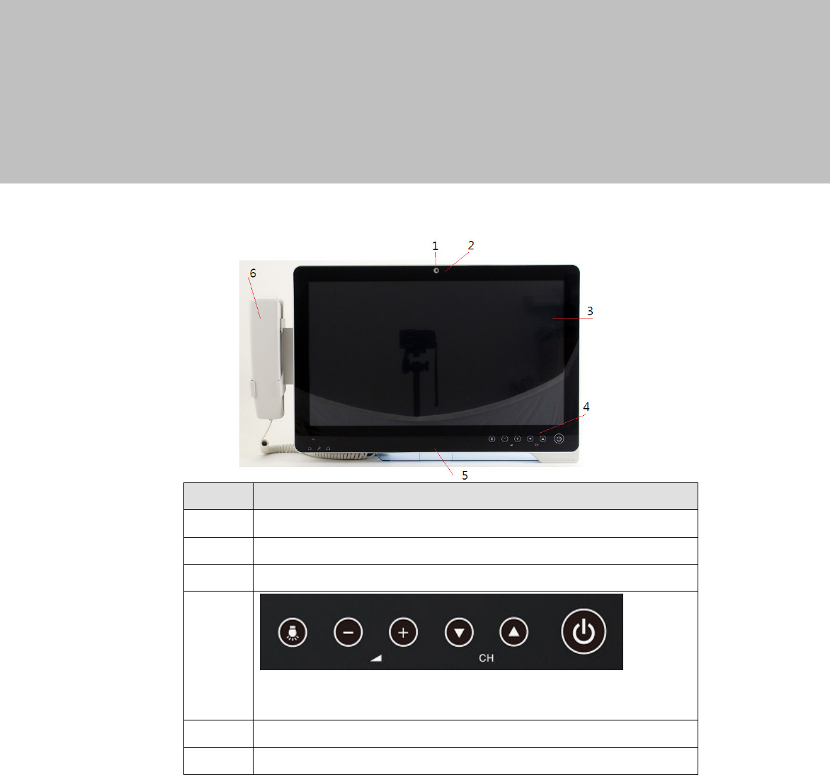
3-1 Front View
Number
Description
1 Build-in camera
2 Camera LED
3 Touch screen
4
Touch keys (from left to right: reading light, volume down,
volume up, channel down, channel up , power button)
5 Smart IC card reader
6 VOIP phone (optional)
4
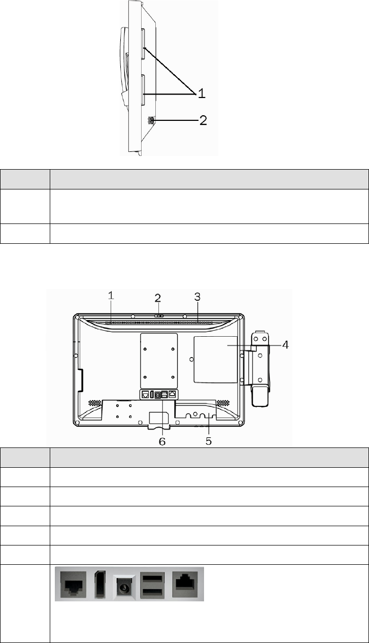
3-2 Side View
Number
Description
1
Combo smart IC card reader with separate RFID antenna
(optional)
2 Speaker
3-3 Rear View
Number
Description
1 Light Sensor
2 Webcam switch
3 Ventilation
4 SSD/HDD door
5 Cable cover
6
Vertical I/O port (from left to right: Nurse call, Display port, DC
jack, USBx2, LAN )
5
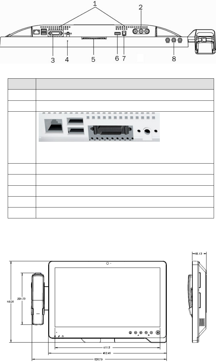
3-4 Bottom View
Number
Description
1 Ventilation
2 From left to right: Video in, Audio left, Audio right (optional)
3
Bottom I/O port (from let to right: LAN, USBx2, Remote, Power
button)
4 Microphone
5 Smart IC card reader
6 USBx1
7 Phone jack (RJ11)
8 From left to right: Audio line-out, Mic-in, Audio line-out
3-5 Dimension
6
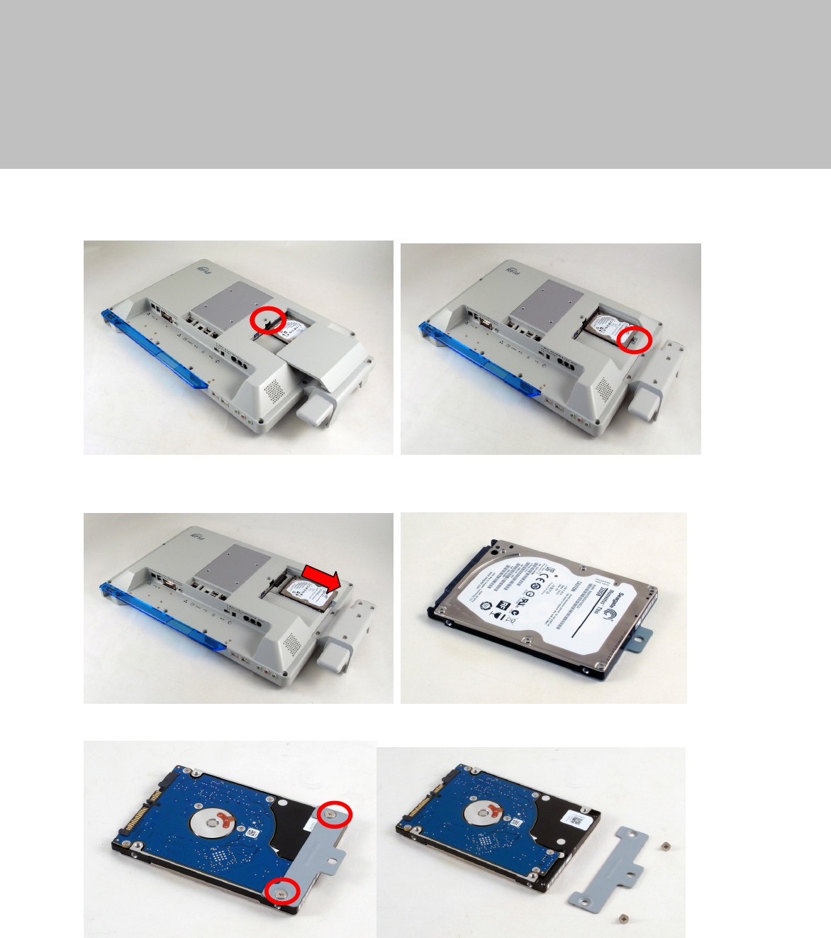
4 System Assembly
4-1 SSD/HDD Replacement
1. Remove the screw (x1) to open the HDD door.
2. Remove the screw (x1) that fixed the HDD to the system.
3. Pull the HDD outward as shown in the picture.
4. The HDD is secured by a metal bracket, remove the screws (x2) to release the metal
bracket from the HDD.
7
5 Peripherals Installation
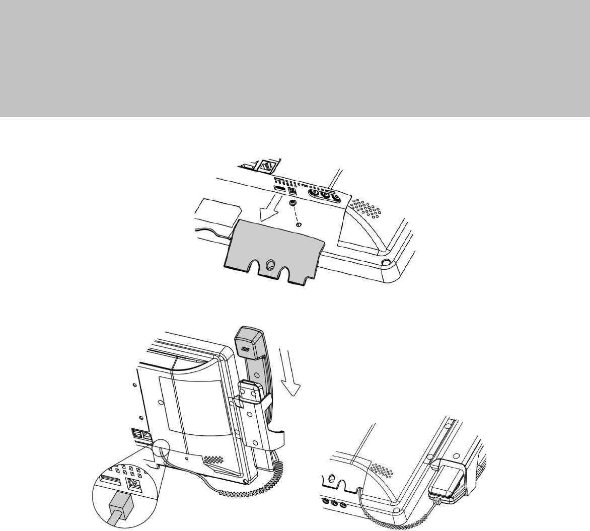
5-1 Phone module Installation
1. Loosen the screw(x1) to open the cable cover.
2. Slide the phone module into the phone holder and connect the
other end of the phone cable to the connector on the system.
8
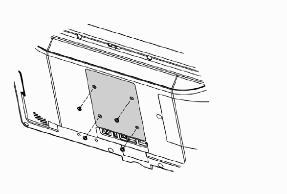
5-2 Stand Installation
2. Fasten the screws.(monitor screw M6x10 4pcs)
9
6 Specification
Model K948
Motherboard C73
Processor Intel Celeron 1047UE
Core Logic CPU with Graphic built-in HM76
System Memory 2 x DDR3 SO-DIMM slot up to 8GB FSB1600Mhz
Graphic Memory DX11, HD Graphic 350MHz
LAN Controller / PHY Intel WG82583V / Intel WG82579V
Audio Controller Realtek ALC 662-GR HD codec
I/O Controller Winbond W83627UHG
Touch TF P-cap 18.5”
Camera LED Green-color (GPIO)
Microphone 1
Power LED Tri-color (GPIO)
Watch Dog Timer Hardware WDT
Display Size 18.5”
Resolution 1366 x 768
Brightness 250 nits
DC-In 12V-48V 5A-1.5A
Storage
HDD Either 2.5" SATA SSD or HDD
Expansion
Mini PCI e 1 x full size slot or half size slot
Side I/O (Back-Left)
Smart IC Card
Reader
(o
p
tional)
1
Rear I/O (Left)
LAN (2nd LAN) 1xRJ45 (with 10/100/1000,LED indicator)
USB 2 (USB 2 .0)
Remote 1x SCSI 26 pin
Reset Button 1, button can be pressed by probe
Power Button 1
Rear I/O (Right)
Composite Video Video in, Audio Left, Audio Right
Line-out 2 (Auto-detect,GPIO), in external IO

10
Model K948
Motherboard C73
Mic-In 1 (Auto-detect,GPIO), in external IO
Vertical I / O
LAN 1 x RJ45 (with 10/100/1000)
Power DC Jack 1 x DVI-D
Display Port 1 x DVI-D
USB 2 (USB 2 .0)
Nurse Call 1 x RJ48
Touch Keys
Power Button 1xPower button (GPIO)
Channel Adjustment 1xChannel up, 1xChannel down (GPIO)
Volume 1xVolume up, 1xVolume down (GPIO)
Reading light 1xReading light(GPIO)
Environment
EMC & Safety FCC Class B, CE, LVD / UL60950 / EN60601
Environment
Operating Temperature 0°C ~ 35°C (32°F ~ +95°F)
Storage Temperature -20°C ~ 60°C (-4°F ~ 140°F)
Humidity 20% - 85% RH non condensing
Weight
Wei
g
ht
5Kgs
Operating System
OS Support
Wind
o
ws Embed
d
ed P
O
SReady7, W
i
nd
o
ws 7, Li
n
ux
Communication
& Peripherals
Speaker
2 x
2.5
W
Build
In
Mic
r
ophone
In
the
b
o
tt
o
m
side
Webcam
5M web cam (USB interface) with webcam door
(w/ fly LED cable to MB & control by GPIO)
VOIP Phone (Front left) Handset module (optional)
Smart IC Card Reader Comply with ISO 7816-1,2,3,T=1 and T=0 protocol
Combo Smart IC Card Reader
(optional) with separate RFID
antenna in the front bezel
Comply with ISO 7816-1,2,3,T=1 and T=0
Support MIFARE, MIFARE+ ,Desfire, PC/SC 2.0, HID
Light Sensor Yes (GPIO)
TV Tuner & DVD Maker Card Mechanical reserved
* This specification is subject to change without prior notice.
Application: Access to patient records / Hospital administration system / Bed management
11
Manufactory information:
Factory: Flytech Technology Co., Ltd.
Address: NO.36 Huaya 3rd Rd., Guishan Township, Taoyuan County 33383, Taiwan
Tel No: 886-3-272-9688 Fax No: 886-3-272-9666
Note: Cleaning solution-Wipe with cloth using clean water, 2 times a
week.
Adaptor Manufacturer: FSP TECHNOLOGY INC.
1. Model: PMP105-18-B15
Rating: 100-240V,47-63Hz,0.7 – 1.4A
2. Model: PMP60-12-B16
Rating: 100-240V,47-63Hz,1.22-0.68A
12
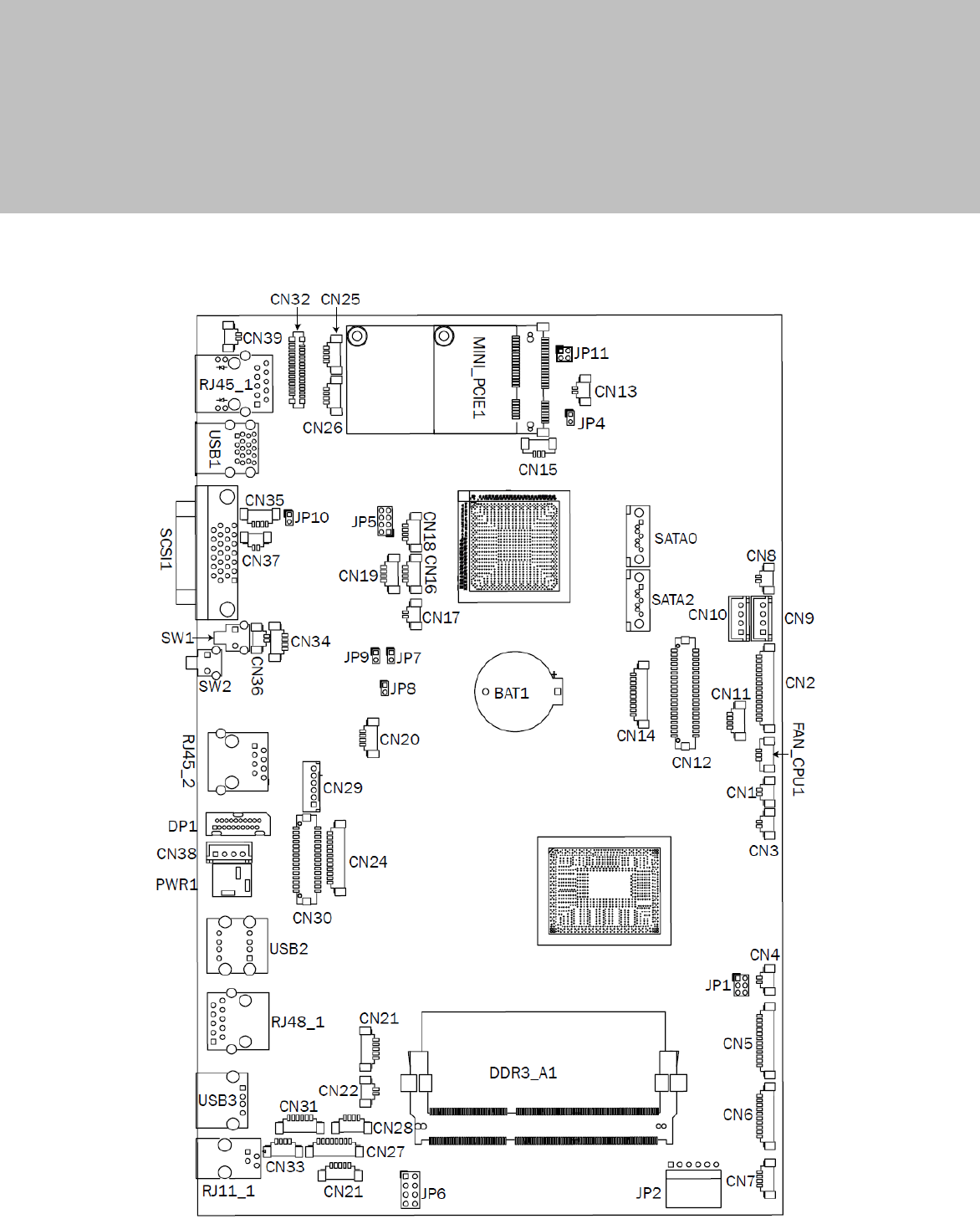
7 Jumper Setting
7-1 C73 Motherboard

13
7-2 Connectors & Functions
Connec
t
or
F
unction
CN2
Scanner
CN3
Nurse Call LED Power
CN4
Build
-
In MIC
CN5
Inverter
CN6
COM5 (for touch)
CN7
USB port for Web Cam
CN8
HDD LED
CN9
SATA Power
CN10
SATA Power
CN1
1
PS/2 keyboard
CN12
LVDS
CN14
COM1
CN16
USB
CN17
Power LED
CN18
USB
CN
1
9
USB
CN20
IrDA
CN22
Reading Light
CN23
Cradle
CN25
USB
CN26
USB
CN27
First Audio Jack
CN28
Second Audio Jack
CN2
9
To front USB board connector
CN30
30P All
-
In
-
One
(Mem
brane, 2D scanner, RFID, Smart
CN
3
1
Speaker & MIC
CN3
2
MSR
CN33
Speaker
CN34
MIC
CN36
Power Button
CN37
LAN LED
CN38
Adaptor Connector
CN39
LAN LED
RJ45_1
LAN1
USB1
USB1, USB2
SCSI 1
SATA
SW1
System Reset
SW2
System Power Bu
tton
RJ45_2
LAN2
DP1
DVI
-
D
PWR1
Adaptor Power Jack
USB2
USB1, USB2
RJ48_1
Nurse Call
USB3
USB
RJ11_1
Handset
SATA0
SATA
SATA1
SATA
FAN_CPU1
CPU Fan
14
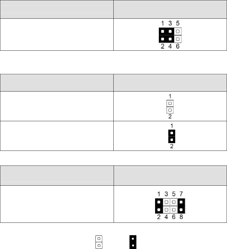
7-3 Jumper Setting
Brightness Type Selection
Function
JP1
(1-2) (3-4) (5-6)
▲LED
Power Mode Setting
Function
JP8
(1-2)
▲ATX Power
AT Power
LCD ID Setting
Function
JP5
(1-2) (3-4) (5-6) (7-8)
18.5” AUO LCD
▲ = Manufacturer Default Setting OPEN SHORT