FLYTECH TECHNOLOGY PB55D31L Swing User Manual Revision v1
FLYTECH TECHNOLOGY CO., LTD Swing Revision v1
Users Manual
Version 1.0 March 2017
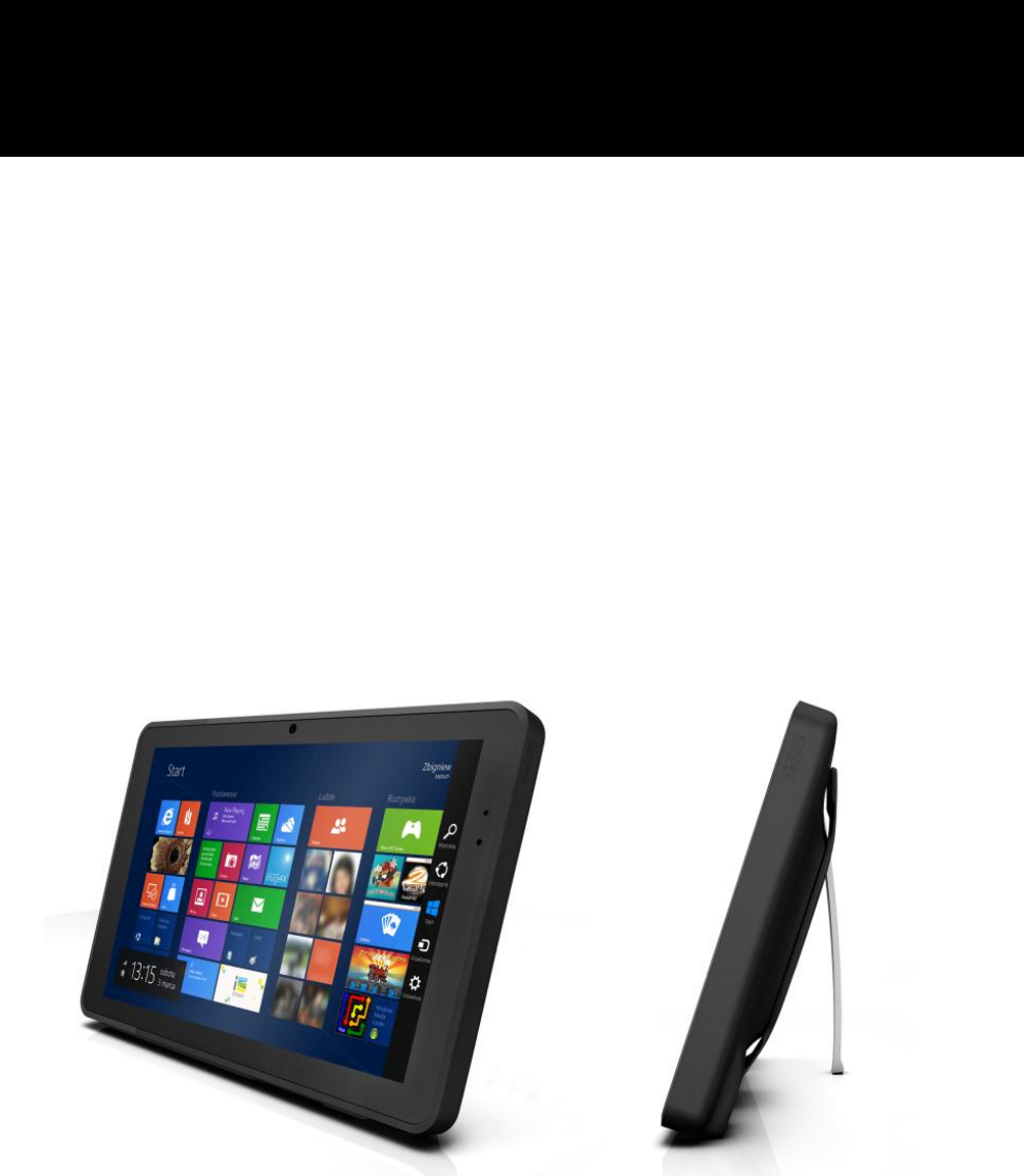
SWING Mobile PC
User Manual
ii
Copyright
Copyright 2017
All Rights Reserved
Manual Version 1.0
The information contained in this document is subject to change without notice.
We make no warranty of any kind with regard to this material, including, but not limited to,
the implied warranties of merchantability and fitness for a particular purpose. We shall
not be liable for errors contained herein or for incidental or consequential damages in
connection with the furnishing, performance, or use of this material.
This document contains proprietary information that is protected by copyright. All rights
are reserved. No part of this document may be photocopied, reproduced or translated to
another language without the prior written consent of the manufacturer.
TRADEMARK
The material in this manual is subject to change without notice.
Bluetooth is a registered trademark of Bluetooth SIG.
Microsoft® , Windows® and ActiveSync® are either registered trademarks or trademarks
of Microsoft Corporation.
All other product or service names are the property of their respective owners.
iii
Safety
Regulatory Information
Caution: Only use approved and UL Listed accessories, battery packs and battery
chargers. Do NOT attempt to charge damp/wet mobile computers or batteries. All
components must be dry before connecting to an external power source.
Power Supply
Use only the approved power supply 50-14000-148 output rated 5 Vdc and minimum 2 A.
The power supply is certified to EN60950-1 with SELV outputs. Use of alternative power
supply will invalidate any approval given to this device and may be dangerous.
Warning for Use of Wireless Devices
Please observe all warning notices with regard to the usage of wireless devices.
Potentially Hazardous Atmospheres
You are reminded of the need to observe restrictions on the use of radio devices in fuel
depots, chemical plants etc. and areas where the air contains chemicals or particles
(such as grain, dust, or metal powders)
and any other area where you would normally be advised to turn off your vehicle engine.
Safety in Aircraft
Switch off your wireless device whenever you are instructed to do so by airport or airline
staff.
Pacemakers
Pacemaker manufacturers recommended that a minimum of 15cm (6 inches) be
maintained between a handheld wireless device and a pacemaker to avoid potential
interference with the pacemaker. These recommendations are consistent with
independent research and recommendations by Wireless Technology Research.
Persons with Pacemakers
Persons with Pacemakers should ALWAYS keep the device more than 15cm (6 inches)
from their pacemaker when turned ON and hence they should not carry the device in a
breast pocket .
Should use the ear furthest from the pacemaker to minimize the potential for
interference.
If you have any reason to suspect that interference is taking place, turn OFF your device.
iv
Hearing Aids
The wireless device may interfere with some hearing aids. In the event of interference
you may want to consult your hearing aid supplier to discuss solutions.
Other Medical Devices
Please consult your physician or the manufacturer of the medical device, to determine if
the operation of your wireless product may interfere with the medical device.
FCC/EU RF Exposure Guidelines
FCC Statement
This equipment has been tested and found to comply with the limits for a Class B digital
device, pursuant to part 15 of the FCC Rules. These limits are designed to provide
reasonable protection against harmful interference in a residential installation. This
equipment generates, uses and can radiate radio frequency energy and, if not installed
and used in accordance with the instructions, may cause harmful interference to radio
communications. However, there is no guarantee that interference will not occur in a
particular installation. If this equipment does cause harmful interference to radio or
television reception, which can be determined by turning the equipment off and on, the
user is encouraged to try to correct the interference by one or more of the following
measures:
Reorient or relocate the receiving antenna.
Increase the separation between the equipment and receiver.
Connect the equipment into an outlet on a circuit different from that to which the
receiver is connected.
Consult the dealer or an experienced radio/TV technician for help.
This device complies with FCC SAR exposure limits set forth for an uncontrolled
environment.
This device complies with Part 15 of the FCC Rules. Operation is subject to the following
two conditions: (1) this device may not cause harmful interference, and (2) this device
must accept any interference received, including interference that may cause undesired
operation.
Caution!
Any changes or modifications not expressly approved by the party responsible for
compliance could void t he user's authority to operate the equipment.

v
CE Marking and European Economic Area
The use of 2.4GHz RLAN's, for use through the EEA, have the following restrictions:
Maximum radiated transmit power of 100 mW EIRP in the frequency range
2.400 -2.4835 GHz
France, outside usage is restricted to 2.4 - 2.454 GHz.
Italy requires a user license for outside usage.
Bluetooth® Wireless Technology for use through the EEA has the following restrictions:
Maximum radiated transmit power of 100mW EIRP in the frequency range
2.400 -2.4835 GHz
France, outside usage is restricted to 10mW EIRP
Italy requires a user license for outside usage.
Battery Information
Our rechargeable battery packs are designed and constructed to the highest standards
within the industry.
However, there are limitations to how long a battery can operate or be stored before
needing replacement.
Many factors affect the actual life cycle of a battery pack, such as heat, cold, harsh
environmental conditions and severe drops.
When batteries are stored over six (6) months, some irreversible deterioration in overall
battery quality may occur. Store batteries discharged in a dry, cool place, removed from
the equipment to prevent loss of capacity, rusting of metallic parts and electrolyte
leakage. When storing batteries for one year or longer, they should be charged and
discharged at least once a year. If an electrolyte leakage is observed, avoid any contact
with affected area and properly dispose of the battery. Batteries must be charged within
the 32° to 95° F (0° to +35° C) ambient temperature range.
Replace the battery when a significant loss of run time is detected.

vi
Battery Caution
Risk of explosion if battery is replaced by an incorrectly type.
Dispose of used battery according to the local disposal instructions.
Waste Electrical and Electronic Equipment (WEEE)
English: For EU Customers: All products at the end of their life must be returned to the
reseller for recycling.
Notational Conventions
The following conventions are used in this document:
Italics are used to highlight specific items in the general text, and to identify
chapters and sections in this and related documents.
bullets (•) indicate:
action items
lists of alternatives
lists of required steps that are not necessarily sequential
Sequential lists (e.g., those that describe step-by-step procedures)
appear as numbered lists.
NOTE This symbol indicates something of special interest or importance to the reader.
Failure to read the note will not result in physical harm to the reader, equipment or data.
CAUTION This symbol indicates that if this information is ignored, the possibility of data
or material damage may occur.
WARNING! This symbol indicates that if this information is ignored the possibility that
serious personal injury may occur.

vii
Revision History
Version
Date
Description
1.0
November 2017
Initial release
viii
Table of Contents
1 Introduction ................................................ 9
1-1 System Overview ................................................................................ 9
1-1-1 Front View .................................................................................... 9
1-1-2 Rear View .................................................................................. 10
1-2 Specification ..................................................................................... 11
1-2-1 Touch Panel ............................................................................... 11
1-2-2 Docking Station- Wall Mount .................................................... 13
1-2-3 Docking Station- Pole Mount .................................................... 13
1-2-4 Docking Station- Hinge Type I/O Box ....................................... 13
1-2-5 Docking Station- Light version I/O Box .................................... 14
1-2-6 Docking Station- Charging Cradle ............................................ 14
2 Getting Started ......................................... 15
2-1 Power On/Off the System ................................................................ 15
2-2 Replacing the Battery....................................................................... 16
2-3 Using the Docking Station ............................................................... 17
2-3-1 Wall Mount ................................................................................ 17
2-3-2 Pole Mount ................................................................................ 18
9
1 Introduction
1-1 System Overview
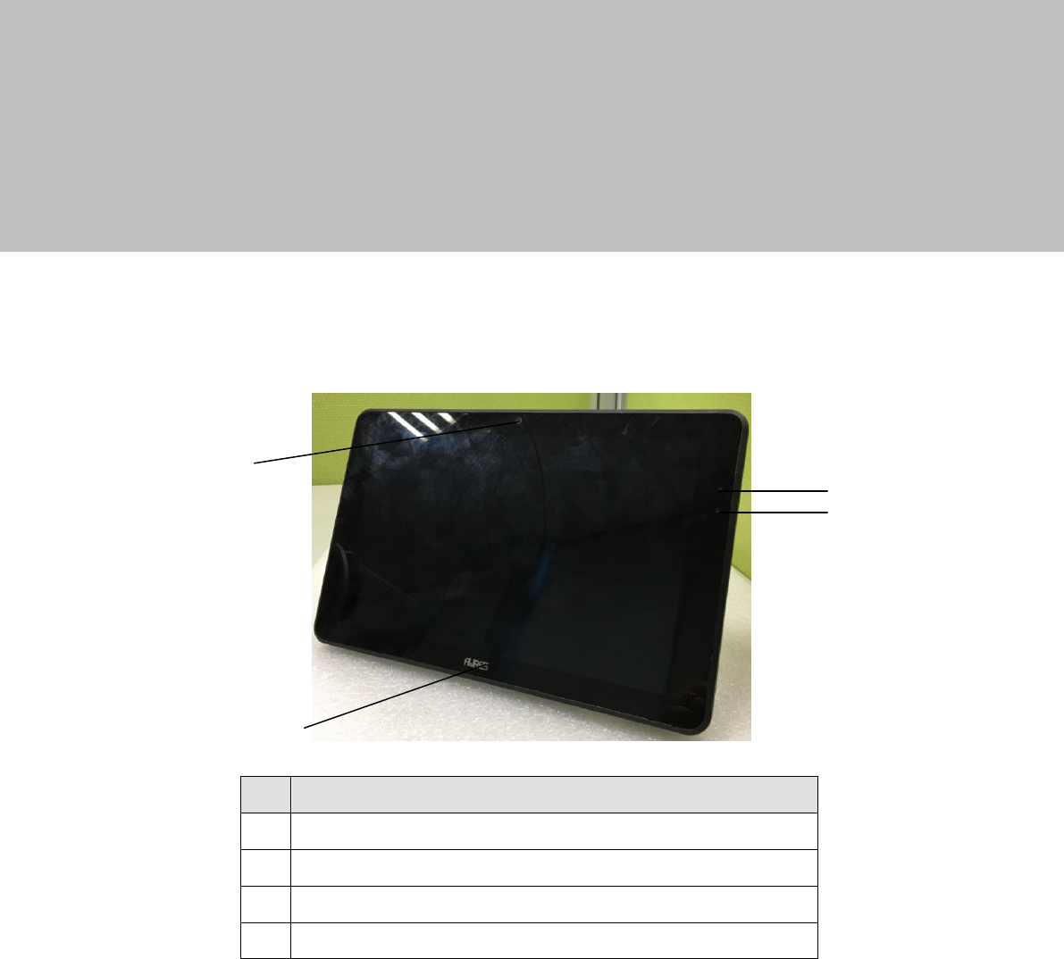
1-1-1 Front View
No.
Description
1
Front Camera
2
Power LED light indicator
3
Ambient light sensor
4
Home key with Aures logo
2
3
4
4
1
4
10
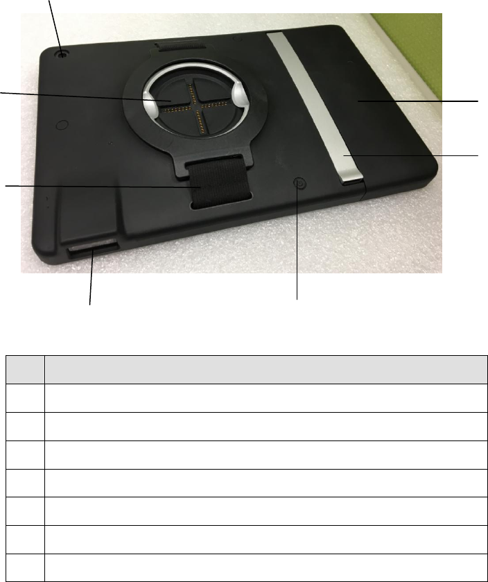
1-1-2 Rear View
No.
Description
5
Rear Camera
6
POGO metal ring
7
Hand strap
8
Scanner
9
Power button
10
Arm Stand
11
Battery
5
6
7
8
9
10
11

11
1-2 Specification
1-2-1 Touch Panel
System
PB55
Motherboard
D31L
CPU
BayTrail - T CR Z3735F 1.33 ~1.83 Ghz quad - core
System memory
2GB DDR3
Flash memory
32GB /64GB eMMC (32GB default )
LCD Touch Panel
LCD size
10.1" TFT LED Panel
Brightness
350nits
Resolution
1920 x 1200
Touch screen
P-CAP Multi-touch
Wireless Networking
Wireless LAN
802.11 a/b/g/n, 2.4G/5GHz
Bluetooth
4.0+LE, Class 2
NFC/RFID
Option ( USB, consigned parts )
3D/SD memory slot
One combo slot built-in (3G and SD memory card option)
Audio
Speaker
1 x 1W Speaker
Control / Indicator
Power Button
1
Scanner button
2
Sensor
G-sensor, Ambient Light Sensor
Vibrator
Built-in vibrator motor
LED Indicator
1 (Battery status indicator) *1
Home key logo
Built-in touch screen
Peripherals
Front Camera
2MP
Rear Camera
5MP
MSR
Hidden connection point for USB MSR or others (option)
Hand strap
1
Scanner
USB 2D scanner (option)
Cradle
USB Port
mini-USB 2.0 x 1
Power Adapter
10W / 5V
Battery & Power
Battery
8000mAh Hot –Swap, Internal backup 1100mAh
Certificate
EMC & Safety
FCC & CE Mark Class B / LVD / SAR for Tablet
FCC & CE Class A/ LVD for Docking Station

12
System
PB55
Motherboard
D31L
Environment
Operating Temperature
(running charging mode)
0°C ~ 35°C (32 °F ~ +95 °F)
Storage Temperature
-10°C ~ 45°C (14°F ~ 114°F)
Operating Humidity
20% - 80% RH non-condensing
Storage Humidity
20% - 80% RH non-condensing
Size
Dimension(W x D x H)
262.3 x 170.3 x 17.3mm
(8.0'' x 5.0'' x 1.3'')
Weight
1085 g
OS Support
Windows IoT 10 Enterprise (32bit) / Android 4.4.4 (64-bit )
*1. Tablet LED indicator: Green light-Full charged / Orange light- Charging / Red flash light- Low
battery / Red light- Critical low battery.

13
1-2-2 Docking Station- Wall Mount
Docking Station
Wall Mount
Lock /Unlock mechanism
1. The POGO connector Lock and Unlock between tablet and
docking station controlled by software
2. Unlock when cradle without power :By cross - shape screwdriver
PH00 for gear access
3. Unlock when cradle with power : By tool access hardware switch
Charging I/O
USB 2.0
1
DC IN
1 ( lock connector )
Charging adapter
65W (DC19V /3.42A)
Color
Black, White
Certificate
FCC /CE Class A, LVD
1-2-3 Docking Station- Pole Mount
Docking Station
Pole Mount
Lock /Unlock mechanism
1. The POGO connector Lock and Unlock between tablet and
docking station controlled by software
2. Unlock when cradle without power :By cross - shape screwdriver
PH00 for gear access
3. Unlock when cradle with power : By tool access hardware switch
Charging I/O
USB 2.0
1
DC IN
1 ( lock connector )
Charging adapter
65W (DC19V /3.42A)
Color
Black, White
Certificate
FCC /CE Class A, LVD
1-2-4 Docking Station- Hinge Type I/O Box
Docking Station
Hinge Type I/O Box
Lock /Unlock mechanism
1. The POGO connector Lock and Unlock between tablet and
docking station controlled by software
2. Unlock when cradle without power :By cross - shape screwdriver
PH00 for gear access
3. Unlock when cradle with power : By tool access hardware switch
Charging I/O
Serial
RS-232 x2 (RJ45 type, with 5V/0V by jumper )
USB 2.0
4 ( I/O port ) / 1 ( side I/O )
Cash Drawer
1 (19V )
LAN
1 (10/100Base–T)
DC IN
1 (lock type )
Charging adapter
1 ( 65W, DC19V/3.42A )
Connection mode with tablet
USB mode and USB roaming mode (By jumper switch )
Color
Black, White
Certificate
FCC /CE Class A, LVD

14
1-2-5 Docking Station- Light version I/O Box
Docking Station
Light version I/O Box
Lock /Unlock mechanism
NA
Charging I/O
Serial
RS-232 x2 (RJ45 type, with 5V/0V by jumper )
USB 2.0
4 ( I/O port ) / 1 ( side I/O )
Cash Drawer
1 (19V )
LAN
1 (10/100Base–T)
DC IN
1 (lock type )
Charging adapter
1 ( 65W, DC19V/3.42A )
Connection mode with tablet
USB mode and USB roaming mode (By jumper switch )
Color
Black, White
Certificate
FCC /CE Class A, LVD
1-2-6 Docking Station- Charging Cradle
Charging Cradle
DC IN
1 (lock type )
Charging adapter
1 ( 65W, 19V/3.42A )
Color
Black
Certificate
FCC /CE Class A, LVD
15
2 Getting Started
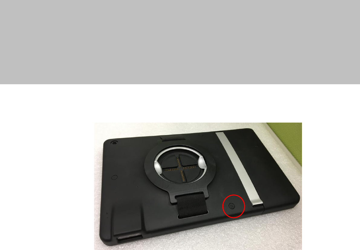
2-1 Power On/Off the System
1. Push the power button to turn on the system and hold 4~5 seconds to turn off
the system.
Note: For best touch performance, remove the protective plastic overlay from the
LCD screen by peeling it away from one of the corners. Be sure to use a soft
pointing device or finger tip to avoid scratching the screen during normal use.
16
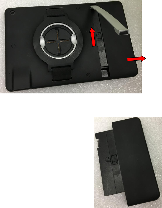
2-2 Replacing the Battery
1. Place the touch panel face down. Making sure not to scratch the screen.
2. Pull the arm stand upwards.
3. Unlock the battery switch.
4. Finally slide the battery module out.
17
2-3 Using the Docking Station
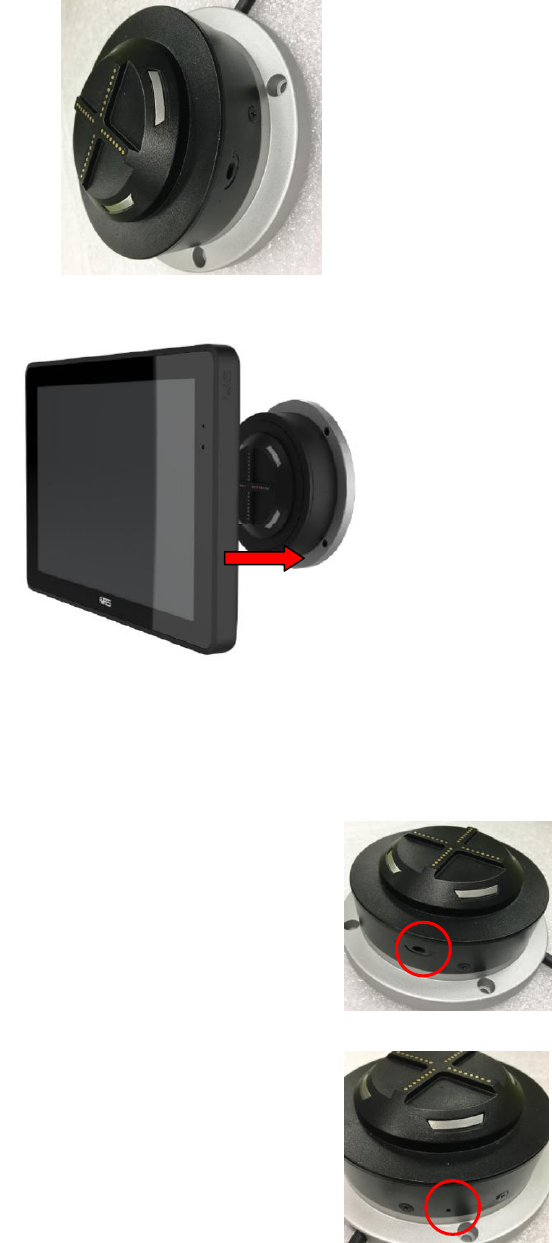
2-3-1 Wall Mount
1. Secure the wall mount to the wall by fastening screws (x4).
2. After the wall mount is fixed, align the touch panel on the wall mount.
Note:
The POGO connector Lock and Unlock between tablet and docking station controlled by software.
Unlock when cradle without power :By cross - shape screwdriver.
Unlock when cradle with power : By tool access hardware switch.
18
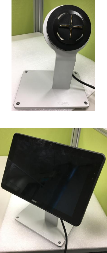
2-3-2 Pole Mount
1. Secure the pole mount on the desk by fastening screws (x4).
2. Directly align the touch panel on the pole mount.
Note:
The POGO connector Lock and Unlock between tablet and docking station controlled by software.
Unlock when cradle without power :By cross - shape screwdriver.
Unlock when cradle with power : By tool access hardware switch.