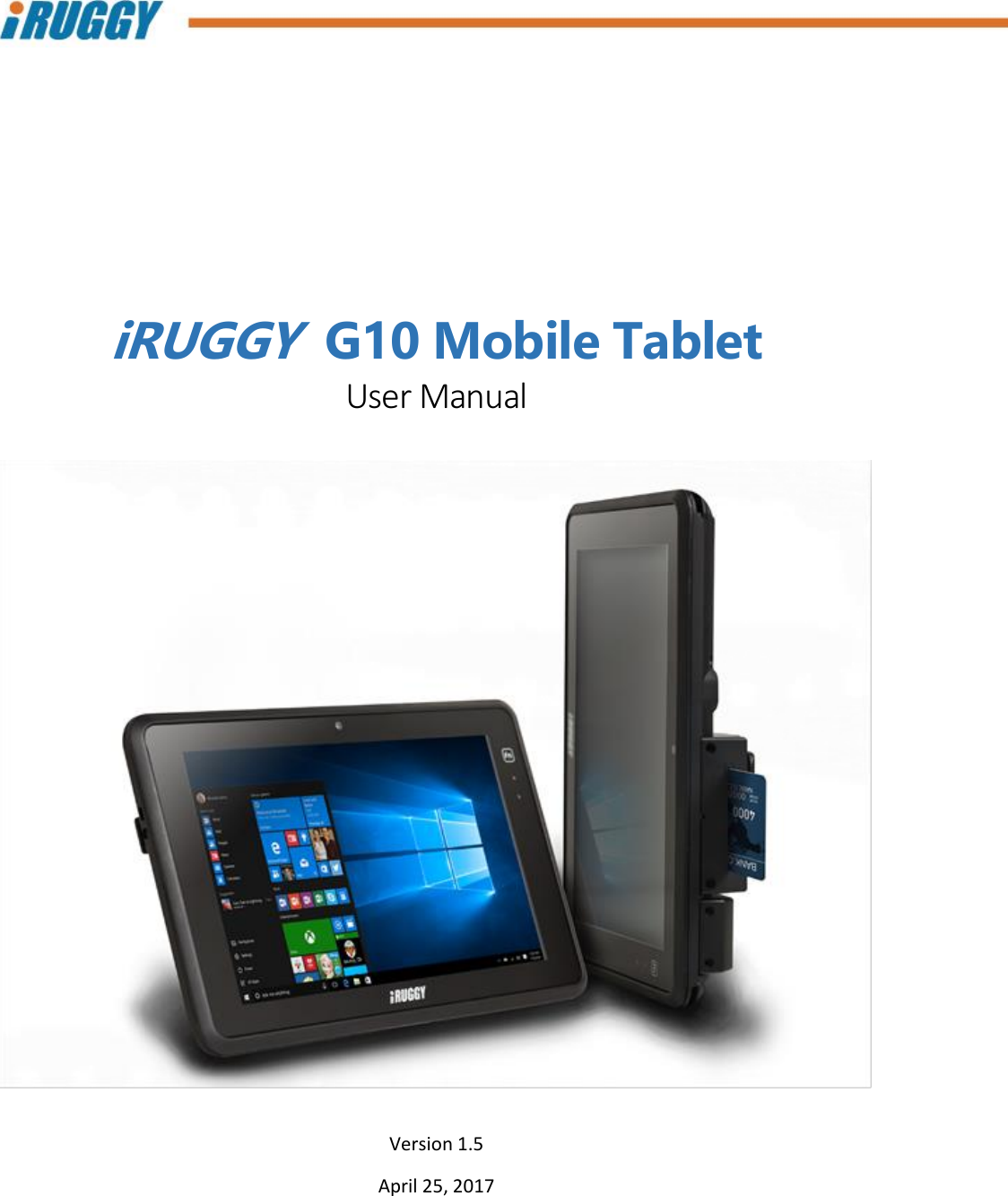
FLYTECH TECHNOLOGY PBG10D41 Mobile POS User Manual
FLYTECH TECHNOLOGY CO., LTD Mobile POS Users Manual
UserManual.wiki
>
FLYTECH TECHNOLOGY
>
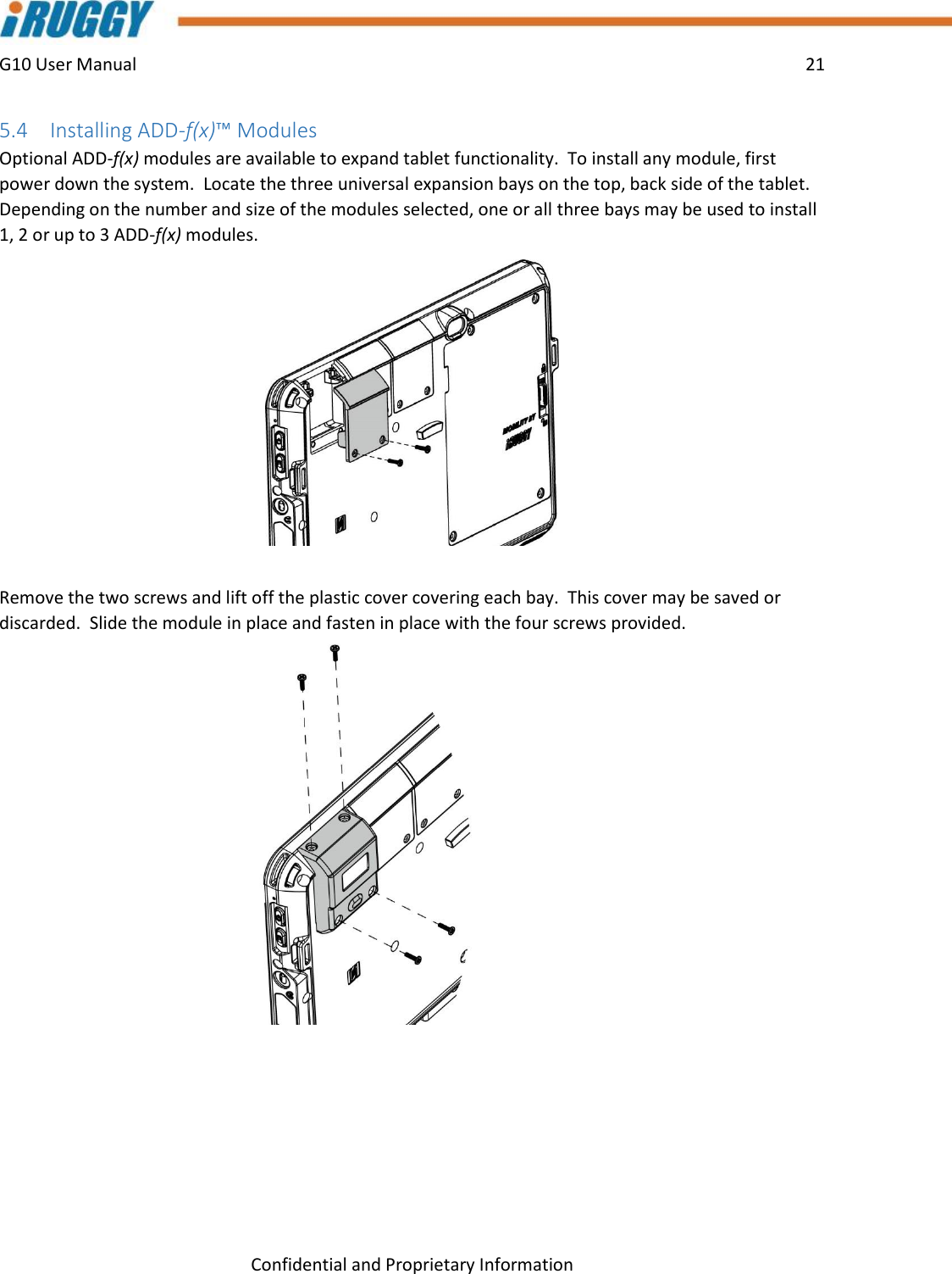
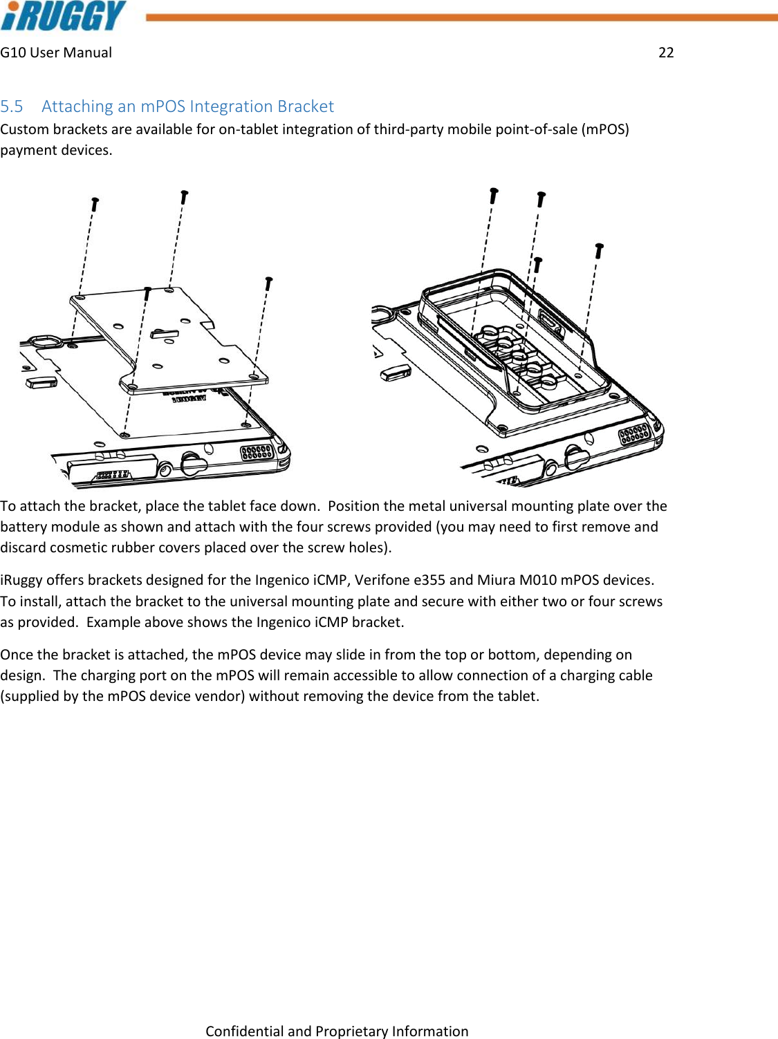
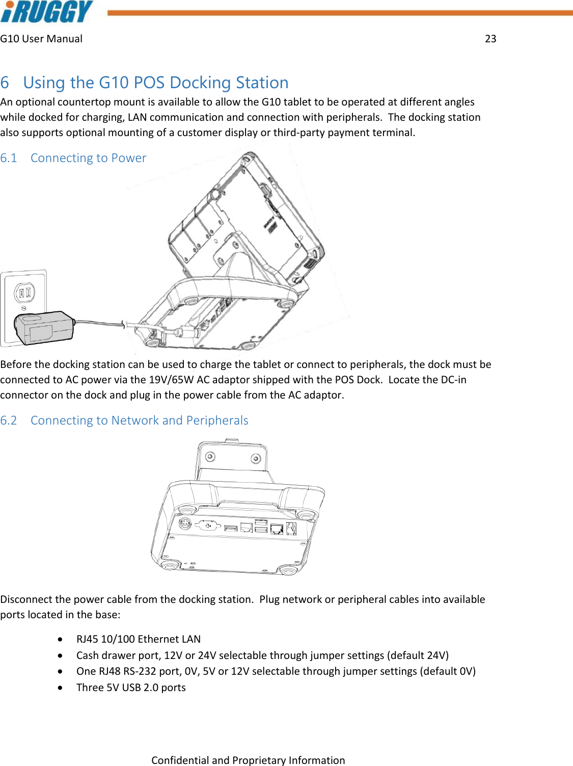
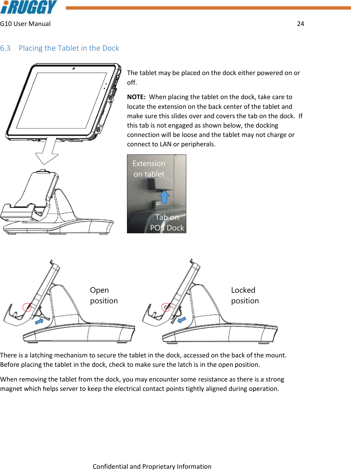
PBG10D41 User Manual
Users Manual
Navigation menu
Upload a User Manual
Namespaces
Wiki Guide
HTML
PDF
Info
Views
User Manual
Discussion / Help
Navigation