FLYTECH TECHNOLOGY T605000 Payment Terminal User Manual Revised
FLYTECH TECHNOLOGY CO., LTD Payment Terminal Users Manual Revised
Users Manual Revised
USER MANUAL
VERSION 1.0 November, 2015
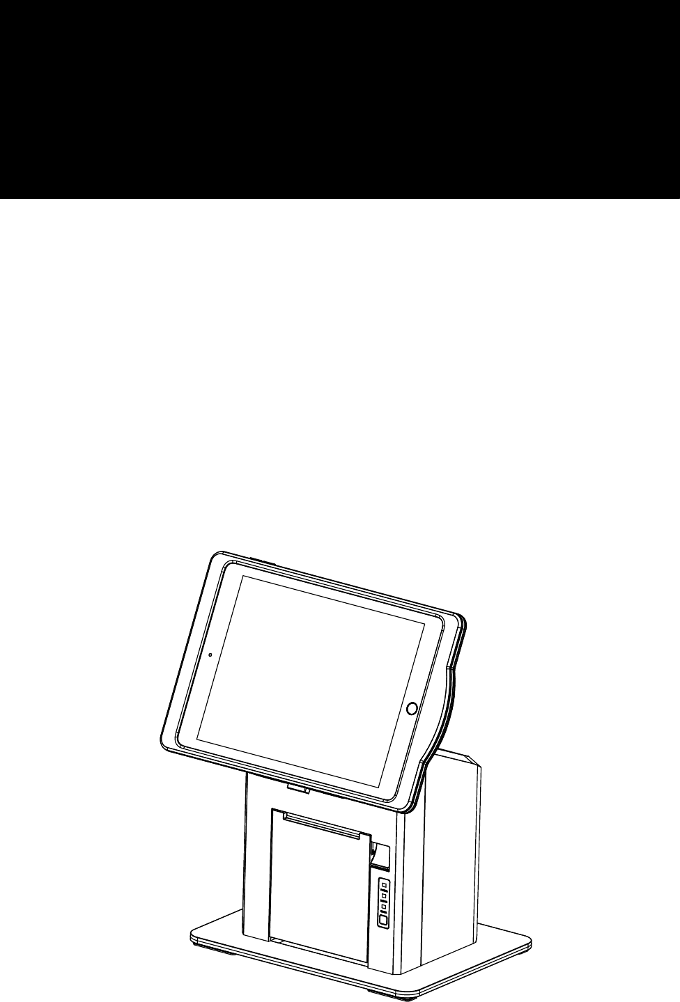
T605
Hardware System

ii
Copyright 2015
All Rights Reserved
Manual Version 1.0
Part Number:
The information contained in this document is subject to change without notice.
We make no warranty of any kind with regard to this material, including, but not limited
to, the implied warranties of merchantability and fitness for a particular purpose.
We shall not be liable for errors contained herein or for incidental or consequential
damages in connection with the furnishing, performance, or use of this material.
This document contains proprietary information that is protected by copyright. All rights
are reserved. No part of this document may be photocopied, reproduced or translated
to another language without the prior written consent of the manufacturer.
Safety
IMPORTANT SAFETY INSTRUCTIONS
1. To disconnect the machine from the electrical power supply, turn off the power switch
and remove the power cord plug from the wall socket. The wall socket must be easily
accessible and in close proximity to the machine.
2. Read these instructions carefully. Save these instructions for future reference.
3. Follow all warnings and instructions marked on the product.
4. Do not use this product near water.
5. Do not place this product on an unstable cart, stand, or table. The product may fall,
causing serious damage to the product.
6. Slots and openings in the cabinet and the back or bottom are provided for ventilation
to ensure reliable operation of the product and to protect it from overheating. These
openings must not be blocked or covered. The openings should never be blocked by
placing the product on a bed, sofa, rug, or other similar surface. This product should
never be placed near or over a radiator or heat register or in a built-in installation
unless proper ventilation is provided.
7. This product should be operated from the type of power indicated on the marking label.
If you are not sure of the type of power available, consult your dealer or local power
company.
8. Do not allow anything to rest on the power cord. Do not locate this product where
persons will walk on the cord.
9. Never push objects of any kind into this product through cabinet slots as they may
touch dangerous voltage points or short out parts that could result in a re or electric
shock. Never spill liquid of any kind on the product.
CE MARK
This device complies with the requirements of the EEC directive 2004/108/EC with
regard to “Electromagnetic compatibility” and 2006/95/EC “Low Voltage Directive”.

iii
FCC
FCC Radiation Exposure Statement
This device complies with part 15 of the FCC rules. Operation is subject to the following
two conditions:
(1) This device may not cause harmful interference.
(2) This device must accept any interference received, including interference that may
cause undesired operation.
FCC Statement
Caution!
Any changes or modifications not expressly approved by the party responsible for
compliance could void the user’s authority to operate the equipment.
Safety Caution
Note: To comply with IEC60950-1 Clause 2.5 (limited power sources, L.P.S)
related legislation, peripherals shall be 4.7.3.2 “Materials for fire enclosure”
compliant.
4.7.3.2 Materials for fire enclosures
For MOVABLE EQUIPMENT having a total mass not exceeding 18kg.the material of a
FIRE ENCLOSURE, in the thinnest significant wall thickness used, shall be of V-1 CLASS
MATERIAL or shall pass the test of Clause A.2.
For MOVABLE EQUIPMENT having a total mass exceeding 18kg and for all
STATIONARY EQUIPMENT, the material of a FIRE ENCLOSURE, in the thinnest
significant wall thickness used, shall be of 5VB CLASS MATERIAL or shall pass the test
of Clause A.1 This product should not be mixed with other commercial wastes for
disposal.
This equipment has been tested and found to comply with the limits for a Class B digital device,
pursuant to part 15 of the FCC rules. These limits are designed to provide reasonable protection
against harmful interference in a residential installation. This equipment generates, uses and can
radiate radio frequency energy and, if not installed and used in accordance with the instructions,
may cause harmful interference to radio communications. However, there is no guarantee that
interference will not occur in a particular installation. If this equipment does cause harmful
interference to radio or television reception, which can be determined by turning the equipment
off and on, the user is encouraged to try to correct the interference by one or more of the
following measures:
-Reorient or relocate the receiving antenna.
-Increase the separation between the equipment and receiver.
-Connect the equipment into an outlet on a circuit different from that to which the receiver is
connected. -Consult the dealer or an experienced radio/TV technician for help.

iv
LEGISLATION AND WEEE SYMBOL
2012/19/EU Waste Electrical and Electronic Equipment Directive on the treatment,
collection, recycling and disposal of electric and electronic devices and their
components.
The crossed dust bin symbol on the device means that it should not be disposed of
with other household wastes at the end of its working life. Instead, the device should
be taken to the waste collection centers for activation of the treatment, collection,
recycling and disposal procedure.
To prevent possible harm to the environment or human health from uncontrolled waste
disposal, please separate this from other types of wastes and recycle it responsibly to
promote the sustainable reuse of material resources.
Household users should contact either the retailer where they purchased this product,
or their local government ofce, for details of where and how they can take this item for
environmentally safe recycling.
Business users should contact their supplier and check the terms and conditions of
the purchase contract.

v
Revision History
Changes to the original user manual are listed below:
Revision Description Date
1.0 •Initial release November, 2015
vi
Table of Contents
1. Packing List .................................. 1
1-1. Standard Accessories .....................................................1
2. System View .................................. 2
2-1. iPad Jacket ......................................................................2
2-2. iPad Jacket with Printer Stand .......................................3
2-3. Dimensions ......................................................................4
2-4. IO Port View .....................................................................5
3. System Assembly & Disassembly 6
3-1. Install the iPad Jacket .....................................................6
3-2. Install iPad Jacket to Printer Stand ................................ 7
3-3. Install the Power Adapter ................................................7
3-4. Connect iPad Jacket to Printer Stand ............................9
3-5. Remove iPad Jacket from Printer Stand ........................9
3-6. Load the Thermal Printer Paper ....................................13
4. Specications .............................. 14
5. Jumper Settings ........................... 15
Appendix: API Information ............... 16
vii
The page is intentionally left blank.
1
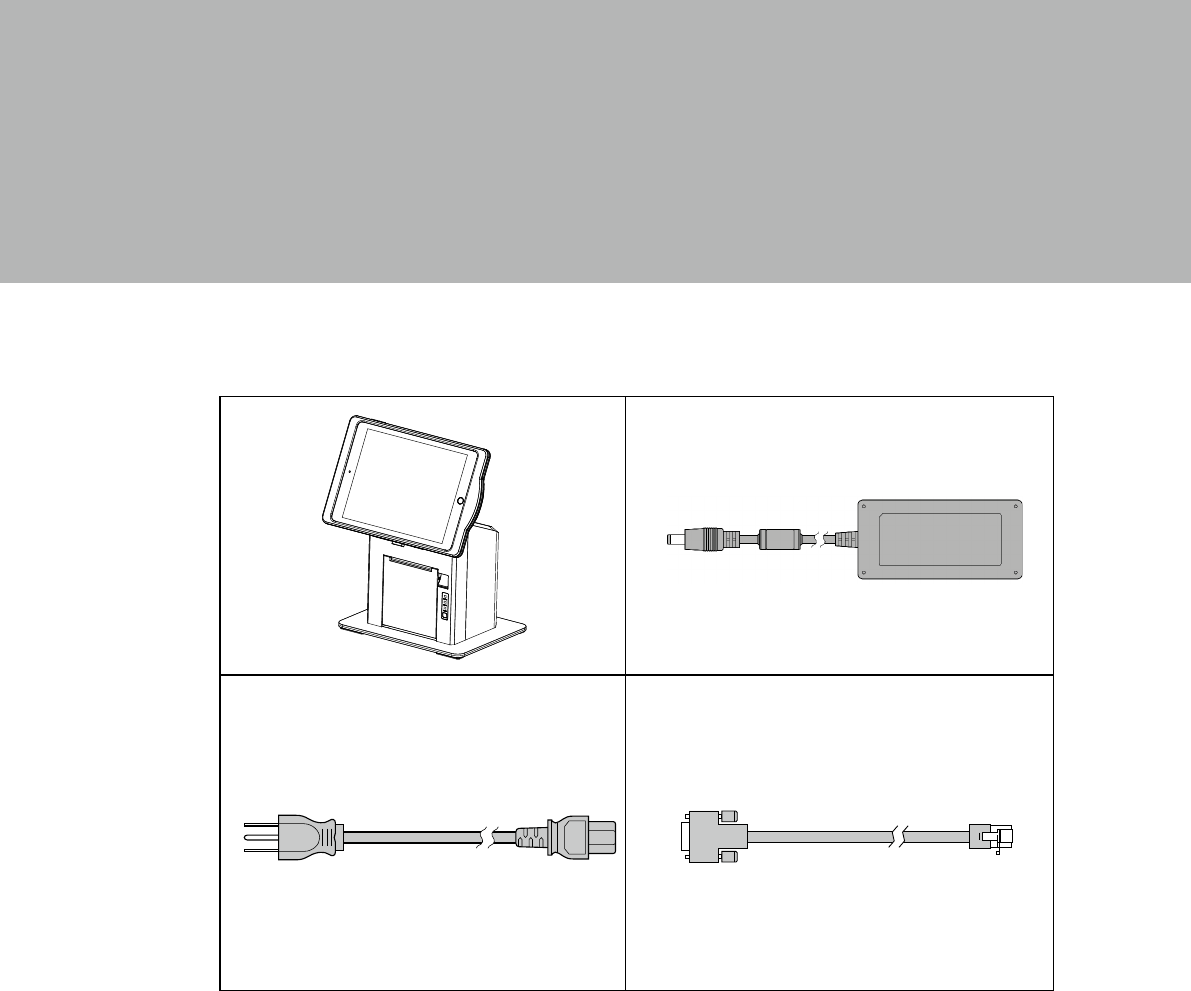
1. Packing List
1-1. Standard Accessories
a. T605 System
b. Power adapter
c. Power cord
d. RJ45-DB9 cable (x2)
2
2. System View
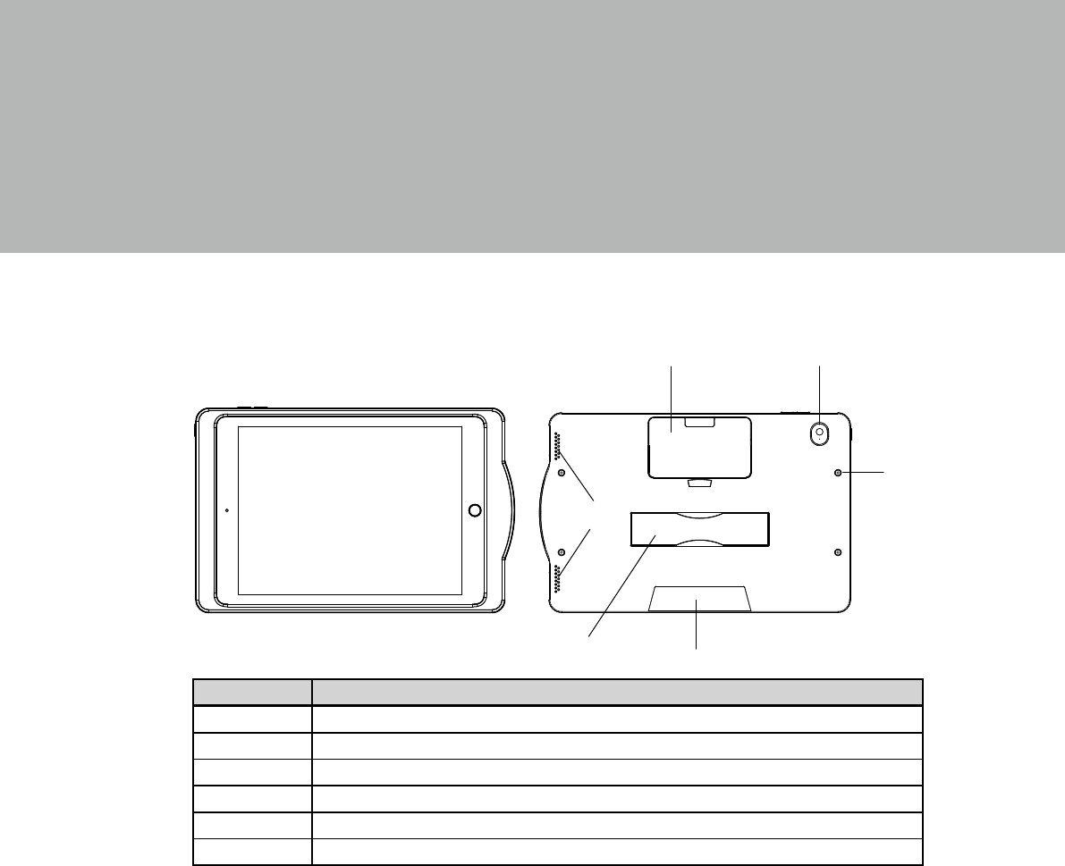
2-1. iPad Jacket
Item No. Description
1 Expansion dummy cover
2 Camera hole
3 Speaker
4 Hand strap
5 Charging slot
6 screw holes (x4)
1 2
3
45
6
3
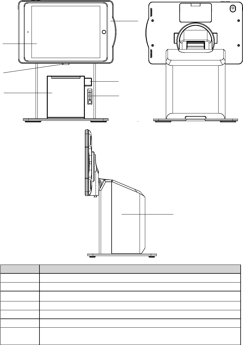
2-2. iPad Jacket with Printer Stand
Item No. Description
1 iPad Air 2 (not included)
2 iPad Jacket
3 Lock button of printer stand
4 Thermal printer
5 Release button
6 Printer indicator (power, error, and paper) & Paper feed button
7System box
(IO board and thermal printer inside)
1
2
4
3
5
6
7
4
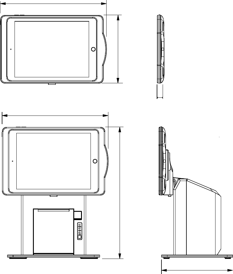
2-3. Dimensions
350 mm
280 mm
188.9 mm
175 mm
280 mm
15 mm
5
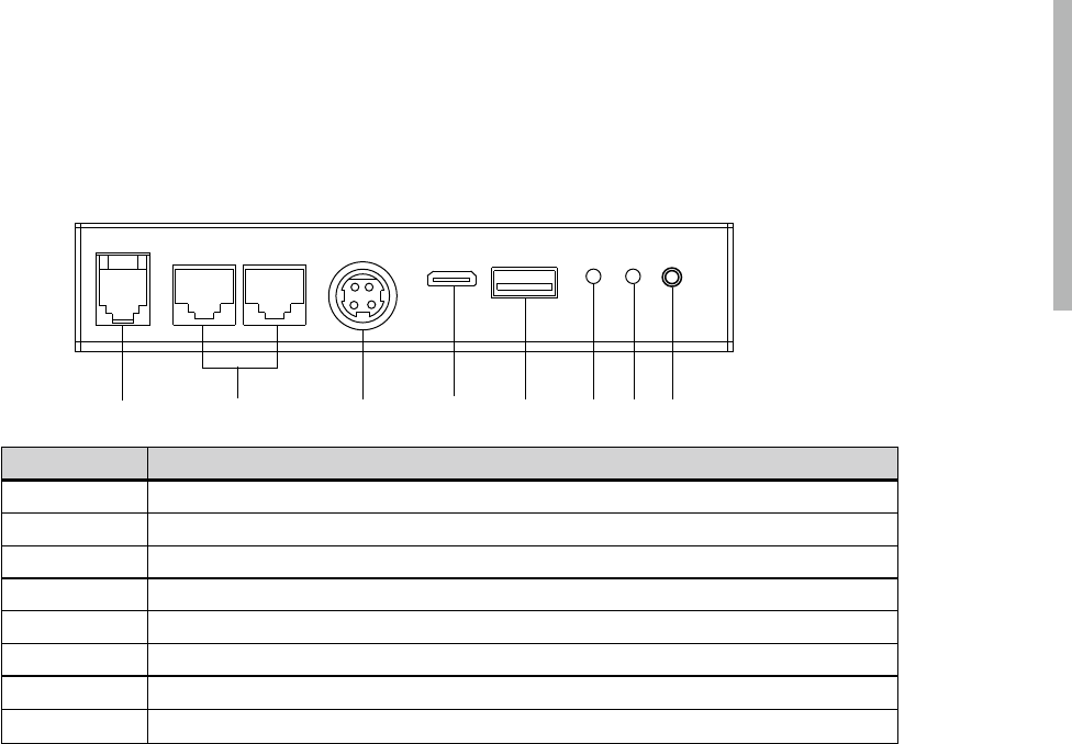
2-4. IO Port View
Item No. Description
a Cash drawer
b COM2/COM1
c DC 19V in
d Micro USB
e USB 2.0
f LED(power)
g LED(paring)
h Paring button
abcdefgh
6
3. System Assembly & Disassembly
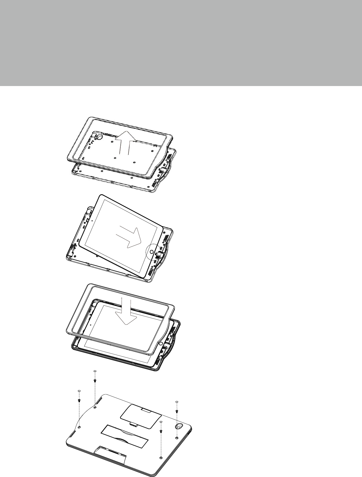
3-1. Install the iPad Jacket
1. Open the top cover of iPad Jacket.
3. Close the top cover of iPad Jacket.
2. Align and place the iPad into the
protective case.
4. Turn to the rear side of iPad Jacket and
then fasten the screws(x4). Make sure
the top cover and bottom shell are
fasten closed.
5. Finally put the rubber pads(x4) on the
screw holes.
7
The system is equipped with a 90W power adapter. Please plug it into the system as
shown below.
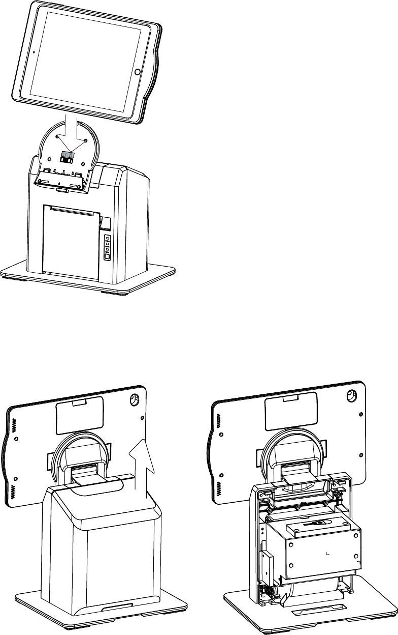
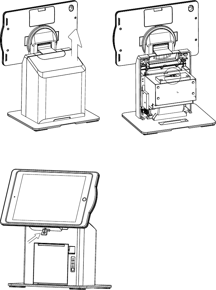
3-2. Install iPad Jacket to Printer Stand
1. Directly put the iPad Jacket into the cradle
of printer stand.
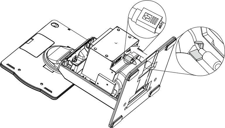
3-3. Install the Power Adapter
1. Use both hands to pull the cover of the system box upward to release the
cover from the system box.
8
2. Place the system face down to access the bottom of the stand.
3. Thread the power adapter cable through the hole of the stand as shown in the picture.
4. Find the power connector on the right of the I/O panel (refer to chapter 2-4 c.) and
connect the power adapter to the DC-IN connector.
5. Finally arrange and x the cable by using the hook as shown in the picture.
Warning:
•Please follow the direction to plug the adapter and make sure it is fully connected
into the I/O port.
•When attaching or detaching the cable, do so by holding the connector, not the
cable itself.
•DO NOT pull or rotate the cable which may cause damage to the tting.
9
1. Open the cover of the system box.
2. You will nd the key on the top of the printer.
When the switch panel on the printer stand shows “Lock“, you can not push the
release button to remove the iPad Jacket. Use the provided key or APP to unlock
printer stand. Please follow the below steps:
3. Insert the key and then pull the iPad
Jacket upward to release it from the
printer stand.
•Manually unlock
10
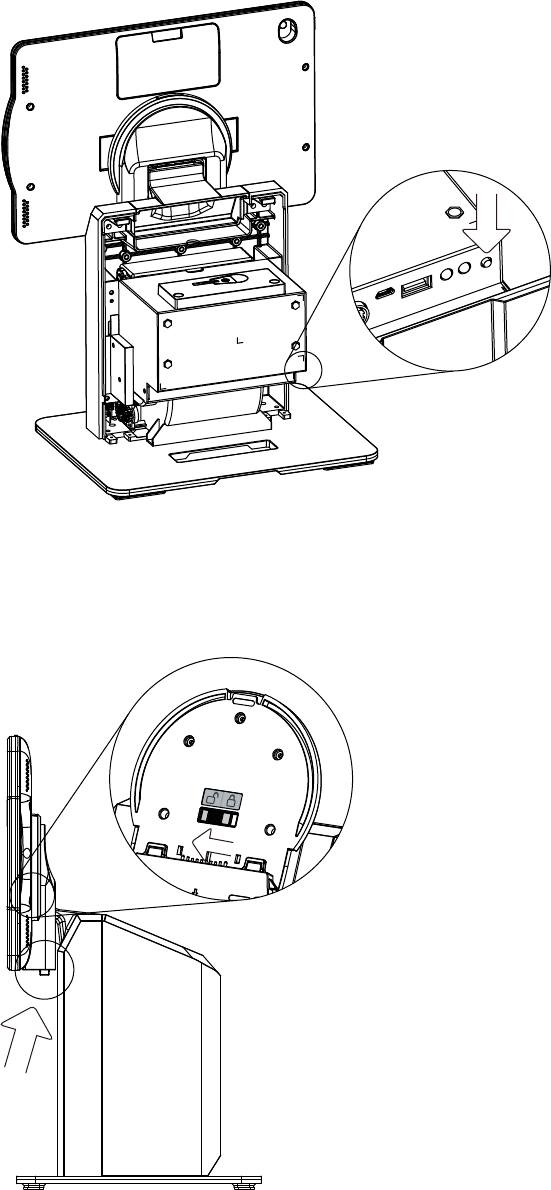
3-4. Connect iPad Jacket to Printer Stand
1. After the power adapter is installed,
remember to push the paring button
on the IO port so that the iPad Jacket
and the printer stand will be connected.
3-5. Remove iPad Jacket from Printer Stand
1. Push the release button on the
printer stand and then pull the iPad
Jacket upward to release it from the
printer stand.
* Please note you can remove iPad
Jacket from the printer stand only on the
condition that the switch panel on the
printer stand shows "unlock". See the
enlarged part in the picture.
11
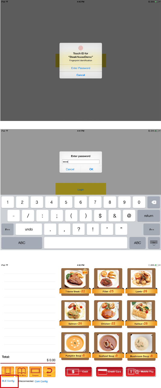
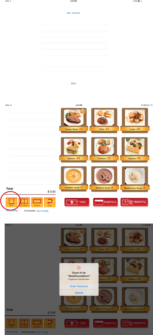
1. Use the Touch ID to login the APP
program.
2. Enter password to login the APP
program if the device is not equipped
with the fingerprint sensor. Default
password:1234.
3. Click "BLE Cong".
•APP unlock (demo APP)
12
4. Click the device to connect.
5. The BLE is now connected, then click
"DOCK"
5. Use the Touch ID or enter the
password to login again.
6. Now the device is unlock, push the
lock button to release the iPad Jacket
from the printer stand.
13
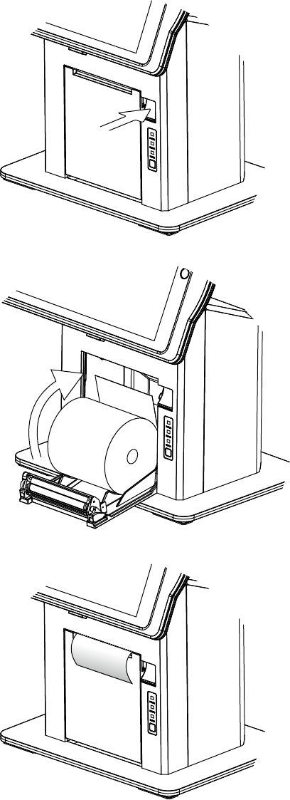
3-6. Load the Thermal Printer Paper
Note: Do not switch off the system. The printer must be powered on when
replacing the printer paper.
1. Press the button at the right side to
open the thermal printer module.
*Cut away the first five (5) cm of
the paper, to obtain a straight
edge and remove the label at the
end of the roll.
2. Place the paper roll inside the
printer slot, pull out a 2 or 3 cm
length and then close the cover.
3. The paper will feed automatically
through the printer (the system
must be powered on).
14
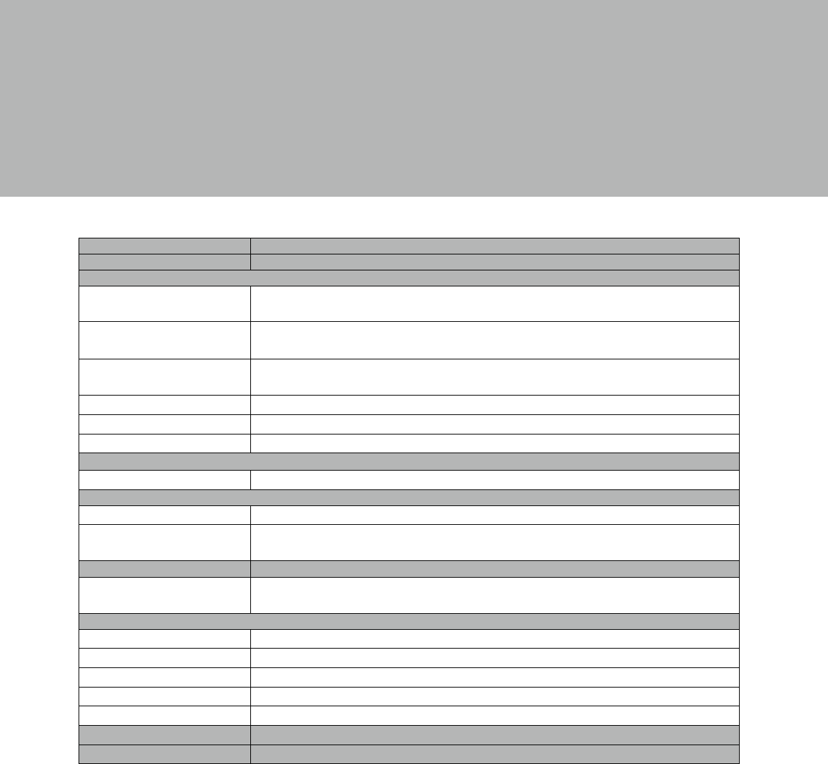
4. Specications
Model T605
Jacket iPad Air 2
External I/O ports(via Bluetooth)
USB 1 x micro USB
1 x USB Type-A for device charging
COM 2 x RJ-48 COM port
(0V/ 5V/12V selection by jumper setting, default 0V)
Cash drawer 1 x RJ-11
(12V/24V selection by jumper setting, default 24V)
DC jack 4 pin w/lock
LED indicator 2 (Pairing, Power)
Bluetooth paring button 1
Power
Power adapter 19V / 90W
Control/Indicator
Printer feed button 1
Printer indicator Paper width 80mm, 170 mm/sec, Auto cutter, Paper drop change, Out of
paper sensor, paper roll dia. 80mm
Peripheral
Built in printer
(via Bluetooth )
3” 170 mm/sec, Auto cutter, Paper drop change, Out of paper sensor, Paper
roll dia. 80mm
Environment
EMC & Safety FCC, Class B, CE, LVD
ESD 4kV contact discharge, 8kV air discharge
Operating Temperature 0°C ~ 35°C (32°F ~ 95°F)
Storage Temperature -20°C ~ 60°C (-4°F ~ 140°F)
Humidity 20% ~ 85% RH non condensing
Dimension (WxDxH) LCD 90° tilt angle: 255 x 224 x 256 mm (10.1” x 8.8” x 10.0”)
Weight (N.W./G.W.) 3.2kg (7.1 lbs) / 4.7kg (9.3 lbs)
* This specication is subject to change without prior notice.
15
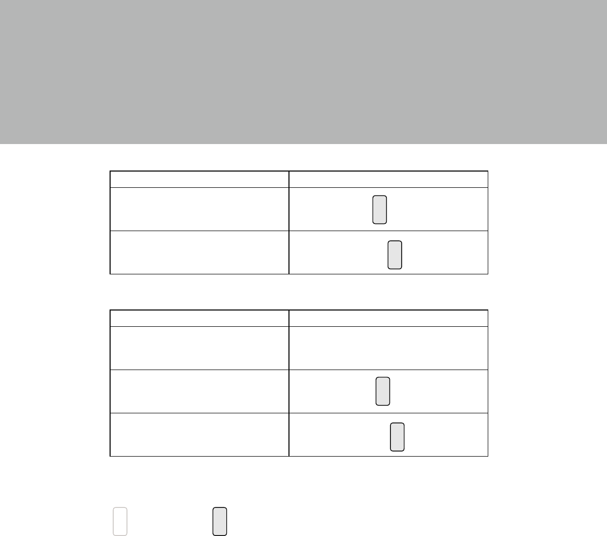
5. Jumper Settings
2
1 3
4
Cash Drawer Power Setting
Function JP2
+12V
▲+24V
COM Power Setting
Function JP3
▲+0V
+5V
+12V
▲ = Manufacturer Default Setting
2
1
Jumper open 2
1
Jumper short
2
1 3
4
2
1 3
4
2
1 3
4
2
1 3
4
16
Appendix: API Information
Please contact your service provider for more detailed informaiton on software
porting guide.