FM Broadcast FM300ES FM300ES FM Transmitter User Manual FM300 500ES 5
FM Broadcast Inc. FM300ES FM Transmitter FM300 500ES 5
Users Manual

PTEK
1723 Little Orchard Street—Unit D
San Jose, CA 95125
Phone—(408) 448-3342 / (888) 889-2958
Fax—(408) 448-3342
World Wide Web—http://www.ptekpower.com
PTEK reserves the right to revise and change any and
all information included in this document.
ES Series
Operating Manual
and User Guide
Version 2.0— Sept 2011
TM
TM
ES Series Operating Manual and User Guide

Copyright © 2009 PTEK
ALL RIGHT S RESERVED. No part of this publication may be reproduced in any form, by
photocopy, microfilm, retrieval system, or by any other means now known or hereafter invented without
the prior written permission of PTEK.
The information in this publication has been carefully checked and is believed to be accurate. However,
PTEK assumes no responsibility for inaccuracies. PTEK retains the right to make changes to this
publication at any time without prior notice. PTEK does not assume any liability arising from the
application or use of this publication or the product(s) described herein.
RESTRICTED RIGHTS LE GEND: Use, duplication, or disclosure by the United States Government
is subject to the restrictions set forth in DFARS 252.227-7013 (c)(1)(ii) and FAR 52.227-19.
PTEK Customer Support
Telephone: (408) 448-3342
Fax: (408) 549-9991
E-mail: service@ptekpower.com
Web Site: http://www.ptekpower.com
ES Series Operating Manual and User Guide
PTEKTM

Revision History
Version 1.0......................................................................................... March 2009
......................................................................... ................... July
Version 1.1 2010
Version 2.0...................................................................... ...................... Sept 2011
ES Series Operating Manual and User Guide
PTEKTM

Warranty Service
The Limited Warranty covers parts and labor to the original purchaser for three years. Damage caused by misuse
or shipping is excluded from the Warranty.
PTEK
Customer Service Manager
1723 Little Orchard Street—Unit D
San Jose, CA 95125
(408) 448-3342
ES Series Operating Manual and User Guide
PTEKTM
Safety Instructions
To maximize user safety and ensure correct device operation, all instructions con-
tained in this section should be read carefully.
Before Applying Power
Verify that the line voltage is 115VAC.
Ground the Exciter
Caution: It is important that the user observe all warnings and instructions that
are on the device and contained in this manual.
Warning: DO NOT OPERATE IN AN EXPLOSIVE ATMOSPHERE
Operation of the FM500ES in the presence of flammable gass es or fumes can
endanger persons proximate to the site of operation.
Caution: NO NOT REMOVE THE EXCITER COVER
Removal of the exciter cover will invalidate the Warranty.
Component replacement and internal adjustments must be
made only by PTEK qualified service personnel.
To minimize shock hazard, the exciter chassis must be connected to an electrical
ground, the exciter must be connected to the AC power mains through a three-
conductor power cable, with the third wire connected to an electrical ground (safety
ground) at the power outlet. Any interr uption of the protective (grounding)
conductor or disconnection of the protective earth terminal will cause a potential
shock hazard that could result in personal injury. If the exciter is to be energized by
any other source be certain that the chassis is connected to a separate safety ground.
ES Series Operating Manual and User Guide
PTEKTM
Fuses
Only fuses with the same required current, voltage rating, and specified type (nor-
mal blow, time delay, etc.) should be use d. Do not use repaired fuses or short-cir-
cuited fuseholders. To do so could cause a shock or fire hazard.
Output Connector
Electrostatic Discharge (ESD)
A sudden discharge of electrostatic electricity can destroy static-sensitive devices
or micro-circuitry. Proper packaging and grounding techniques are necessary pre-
cautions to prevent damage. Always take industry-standard precautions.
Grounding Methods
Guard against electrostatic damage at workstations by following these steps:
1. Cover workstations with approved anti-static material. Provide a wrist strap connect-
ed to a work surface and properly grounded tools and equipment.
2. Use anti-static mats, heel straps, or air ionizers to give added protection.
3. Handle electrostatic-sensitive components, boards, and assemblies by the case or the
PCB edge.
4. Avoid contact with pins, leads, or circuitry.
5. Turn off power and input signals before inserting and removing connectors or test
equipment.
6. Keep the work area free of non-conductive materials such as ordinary plastic assem-
bly aids and Styrofoam.
7. Use field service tools, such as cutters, screwdrivers, and vacuums that are conduc-
tive.
Warning: The type-N output connector carries dangerously high RF voltages
that present shock and burn hazards. Never operate the exciter with-
out properly terminating the output connector in either an adequately rated load
or antenna.
ES Series Operating Manual and User Guide
PTEKTM

General Safety Rules
• The device must be used in accordance with the instructions for use.
• Electrical installations in the room must correspond to the requirements of respective regu-
lations.
• Take care that there are no cables, particularly mains cables, in areas where persons can trip
over them.
• Do not use a mains connection in sockets shared by a number of other power consumers. Do
not use an extension cable.
• Only use the mains cable supplied.
• The unit is completely disconnected from the power source only when the power cord is dis-
connected from the power source. Therefore the power cord and its connectors must always
remain easily accessible.
• Do not set up the device in the proximity of heat sources or in a damp location. Make sure
the device has adequate ventilation.
• All plugs on the connection cables must be screwed or locked to the chassis housing.
• The device is designed to be used in horizontal position only.
• The device is no longer safe to operate when the device has visible damage or the device no
longer functions.
• In case of system malfunction or visible damage to the FM500ES, the device must be shut
down and secured against unintentional operation.
• Repairs may only be carried out by a person authorized by PTEK.
• If extensions are made to the FM500ES, the legal stipulations and the device specifications
must be observed.
• The FM500ES must be switchedoff and the line cord disconnected from the AC source
when removing the top cover.
ES Series Operating Manual and User Guide
PTEKTM

ES Series Operating Manual and User Guide
PTEKTM

Table of Contents
Limited Warranty .................................................................................................................iv
Warranty Service .................................................................................................................. iv
Safety Instructions ...................................................................................................................v
Preface ................................................................................................................................... xiii
Website Information ........................................................................................................... xiv
Your Comments are Welcome ............................................................................................ xiv
Notes, Cautions, Warnings, and Sidebars ...........................................................................xv
1. Overview and Specifications ........................................................................................ 1-1
1.1 Overview ................................................................................................................ 1-1
1.2 Specifications ......................................................................................................... 1-4
1.2.1 General ....................................................................................................... 1-4
1.2.2 Electrical .................................................................................................... 1-5
1.2.2.1 System Power ............................................................................. 1-5
1.2.3 Environmental ............................................................................................ 1-6
1.2.3.1 Shock .......................................................................................... 1-6
1.2.3.2 Electrostatic Discharge ............................................................... 1-6
1.2.3.3 Noise Level ................................................................................. 1-6
1.3 Packaging and Shipping ......................................................................................... 1-7
1.3.1 Rack-Mount Slides (Optional) ................................................................... 1-7
2. Installation ..................................................................................................................... 2-1
2.1 Installation Procedures ........................................................................................... 2-1
2.2 Removing the Protective Top Cover ..................................................................... 2-2
2.3 Removing a Power Supply .................................................................................... 2-2
2.4 Changing the Fuse ................................................................................................. 2-5
2.5 Cleaning the Air Filter ........................................................................................... 2-6
ES Series Operating Manual and User Guide
PTEKTM

2.6 Rack Mounts .......................................................................................................... 2-7
2.6.1 Mounting Brackets ..................................................................................... 2-7
2.6.2 Rack-Mount Slides (Optional) ................................................................... 2-8
3. Operation ....................................................................................................................... 3-1
3.1 Set Up the System .................................................................................................. 3-1
3.2 Power Up the System ............................................................................................. 3-2
3.3 Getting Started ....................................................................................................... 3-4
3.3.1 Startup Sequence ........................................................................................ 3-4
3.3.2 Changing the Stereo Encoder .................................................................... 3-5
3.3.3 Audio ......................................................................................................... 3-6
3.3.4 Final Check ................................................................................................ 3-7
3.4 Additional Adjustments ......................................................................................... 3-9
3.5 Tune Up the Antenna ........................................................................................... 3-10
3.6 Power Down the System ...................................................................................... 3-11
Appendix A. Connector Pinouts ...................................................................................... A-1
A.1 Accessory Port ...................................................................................................... A-1
Appendix B. Rack-Mount Slide Installation ...................................................................B-1
Index ................................................................................................................ Index-1
Reader Comment Card
ES Series Operating Manual and User Guide
PTEKTM

List of Figures
Figure 1-1 FM500ES FM Stereo Broadcast Transmitter .................................................. 1-1
Figure 1-2 FM500ES System Block Diagram................................................................... 1-2
Figure 1-3 FM500ES Front Panel ..................................................................................... 1-2
Figure 1-4 FM500ES Open Top View (A) and Rear Panel (B) ........................................ 1-3
Figure 2-1 FM500ES Right-Side Top Cover Phillips Screws........................................... 2-2
Figure 2-2 Remove the Four Phillips Screws from the
Power Supply Mounting Plate 2-3
Figure 2-3 Disconnect Five Wires before Removing Power Supplies.............................. 2-4
Figure 2-4 Remove Fuse Holder to Remove Fuse ............................................................ 2-5
Figure 2-5 Remove the Front Panel Screws to Access the Air Filter................................ 2-6
Figure 2-6 Remove the Exposed Air Filter ....................................................................... 2-6
Figure 2-7 Make Sure the Air Vent Hole s are Unobstructed ............................................ 2-6
Figure 2-8 Left and Right Rack-Mount Brackets.............................................................. 2-7
Figure 3-1 FM50o0ES Rear-Panel Connectors ................................................................... 3-2
Figure 3-2 Plug the Power Cord into the FM500ES AC Power Socket............................ 3-3
Figure 3-3 After Power has been Applied to the FM500ES, it enters Standby mode....... 3-3
Figure 3-4 After the OPERATE Key is Pressed, the Startup Sequence Begins................ 3-4
Figure 3-5 Stereo Encoder Can be Changed Through the LCD Display .......................... 3-5
Figure 3-6 Press the RAISE or LOWER key to Change the LCD Display....................... 3-5
Figure 3-7 The Deviation Screen is Displayed through the FUNCTION Key ................. 3-6
Figure 3-8 Audio Gain Can be Adjusted Through the LCD Display................................ 3-6
Figure 3-9 Press the FUNCTION Key to read Frequency ................................................ 3-7
Figure 3-10 Press the FUNCTION Key to read Audio Gain .............................................. 3-7
Figure 3-11 Press the FUNCTION Key to read VOLTS & AMPS .................................... 3-8
Figure 3-12 Press the FUNCTION Key to read Forward & Reverse Power ...................... 3-8
Figure 3-13 Press the FUNCTION Key to read Deviation ................................................. 3-8
Figure 3-14 Press LOWER/RAISE/FUNCTION Keys Simultaneously............................. 3-9
ES Series Operating Manual and User Guide
PTEKTM

Figure 3-15 TO COME........................................................................................................ 3-9
Figure 3-16 TO COME...................................................................................................... 3-10
Figure 3-17 TO COME...................................................................................................... 3-10
Figure A-1 Accessory Port Pinout..................................................................................... A-1
Figure B-1 FM500ES Right-Side Rack-Mount Slide Holes.............................................. B-2
Figure B-1 FM500ES FM Stereo Broadcast Transmitter
Rack-Mount Slide Installation B-3
Figure B-2 CLB-203 Rack-Mount Slide with Quick Disconnect ...................................... B-4
List of Tables
Table 1-1 FM500ES General Specifications................................................................... 1-4
Table 1-2 FM500ES Electrical Specifications ................................................................ 1-5
Table 1-3 Typical Noise Levels of the FM500ES........................................................... 1-6
Table A-1 Accessory Port Pinout Signal Descriptions ................................................... A-2
ES Series Operating Manual and User Guide
PTEKTM

Preface
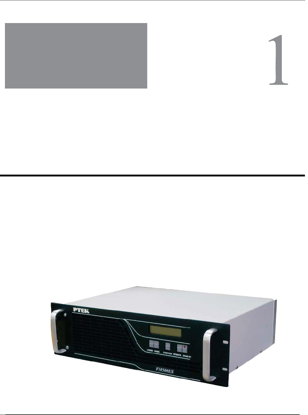
FM500ES FM Stereo Broadcast Transmitter
This document, , provides instructions on
how to install, configure, power up, and perform diagnostics on the 50, 150, 300
and 500 Watt PTEK ES FM Broadcast Transmitter (see photo below), an easy-to-
use and versatile system that can be used in either stand-alone or backup mode.
The information contained within is intended for an experienced system operator
with a knowledge of high-performance broadcast transmission systems. The
3RU-high (3.5”) FM300-500ES designed to fit a standard is 19” rack
rack-mount slides are also available.
ES Operating Manual and User Guide
Optional
ES Series Operating Manual and User Guide
PTEKTM

Key features of the ES FM Stereo Broadcast Transmitter include:
• Totally solid-state no-tune construction
• Wide input range from 88 to 264 VAC
• 3-year warranty on all parts and labor
• Built-in field-programmable FSK ID for translator use
• Remote-control interface
• Optional built-in stereo encoder
• Rugged design withstands up to 5G forces and 50°C
• Meets or exceeds all FCC and CCIR standards
• Designed and manufactured in the United States
Website Information
PTEK corporate and product information may be accessed on the World Wide Web
by browsing the website http://www.ptekpower.com .
Your Comments are Welcome
We are interested in improving our documentation and welcome your comments and
suggestions. You can email your comments to us at docfeedback@ptekpower.com .
Please include the document part number in the subject line of your email.
Frequency stability for each unit is ensured by using PLL (phase-locked loop)
frequency synthesis from a highly stable crystal oscillator. All units incorporate over-
temperature protection and VSWR foldback to automatically reduce power output to
safe operating levels Switch-mode power supplies provide consistent performance
even when there are frequent power outages and voltage fluctuations that make
stressful demands of power dependence. An overview and specifications of the ES FM
Stereo Broadcast Transmitters is given in Chapter 1, "Overview and Specifications", of
this manual.
ES Series Operating Manual and User Guide
PTEKTM
Notes, Cautions, Warnings, and Sidebars
The following icons and formatted text are included in this document for the reasons
described:
Note: A note provides additional information concerning the procedure or action
being described.
Caution: A caution describes a procedure or action that may result in injury to the op-
erator or equipment. This may involve—but is not restricted to—heavy equipment or
sharp objects. To reduce the risk, follow the instructions accompanying this symbol.
Warning: A warning describes a procedure or action that may cause injury to the
operator or equipment as a result of hazardous voltages. To reduce the risk of elec-
trical shock and danger, follow the instructions accompanying this symbol.
Sidebar: A “sidebar” adds detail to the section within which it is placed,
but is not absolutely vital to the description or procedure of the section.
ES Series Operating Manual and User Guide
PTEKTM

ES Series Operating Manual and User Guide
PTEKTM
1FM150ES FM Stereo Broadcast Transmitter
Overview and Specifications
1.1 Overview
Figure 1-1. FM500ES FM Stereo Broadcast Transmitter
General
Section
Chapter
The 3RU-high (5.25”) ES Series FM Stereo Broadcast Transmitter is designed
to fit a standard 19” rack and is provided with rack-mount left and right brackets
and handles. Optional rack-mount slides are also available. The are
rugged enough to withstand extreme shock (up to 5G), temperature (up to
50°C), and EMI such as that associated with broadcasting from remote rugged
environments. (see
Figure 1-1; a block diagram is given in Figure 1-2, page 1-2). The
supports Mono, Wideband Stereo (left and right) and SCA inputs, ideal for a
variety of commercial and dedicated stereo broadcast transmission
applications.
ES Series
ES Series
ES Series Operating Manual and User Guide
PTEKTM
The FM500ES is designed within a 3RU-high (5.25”) form-factor that is 13.75” (34.9
cm) deep (including the front panel and rear protective flanges; the chassis body itself
is 13” deep) and 17” (43.2 cm) wide (19” including the frontpanel to fit a standard-
size rack).
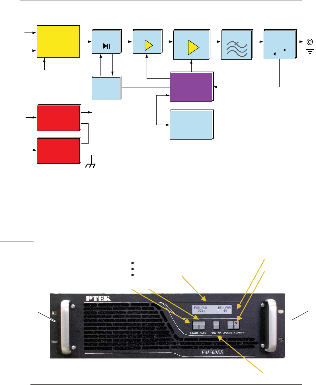
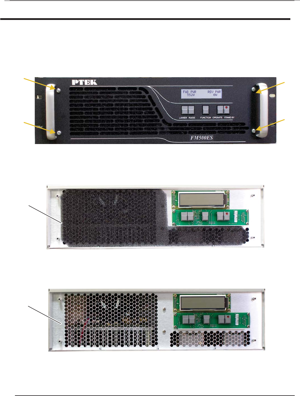
Features on the FM500ES front panel are shown inFigure 1-3 .
Figure 1-2. FM500ES System Block Diagram
Figure 1-3. FM500ES Front Panel
Audio Input
Power
Switching
Supply
Power
Switching
Supply
MPX
24V
24V
36V
48V
VCO
PLL
Frequency Data
SCA
Mono
VAC
VAC
Directional
Coupler
RF Driver RF Amplifier
Level-Control
Microprocessor
Metering
LPF
Air Vent (Filter Behind)
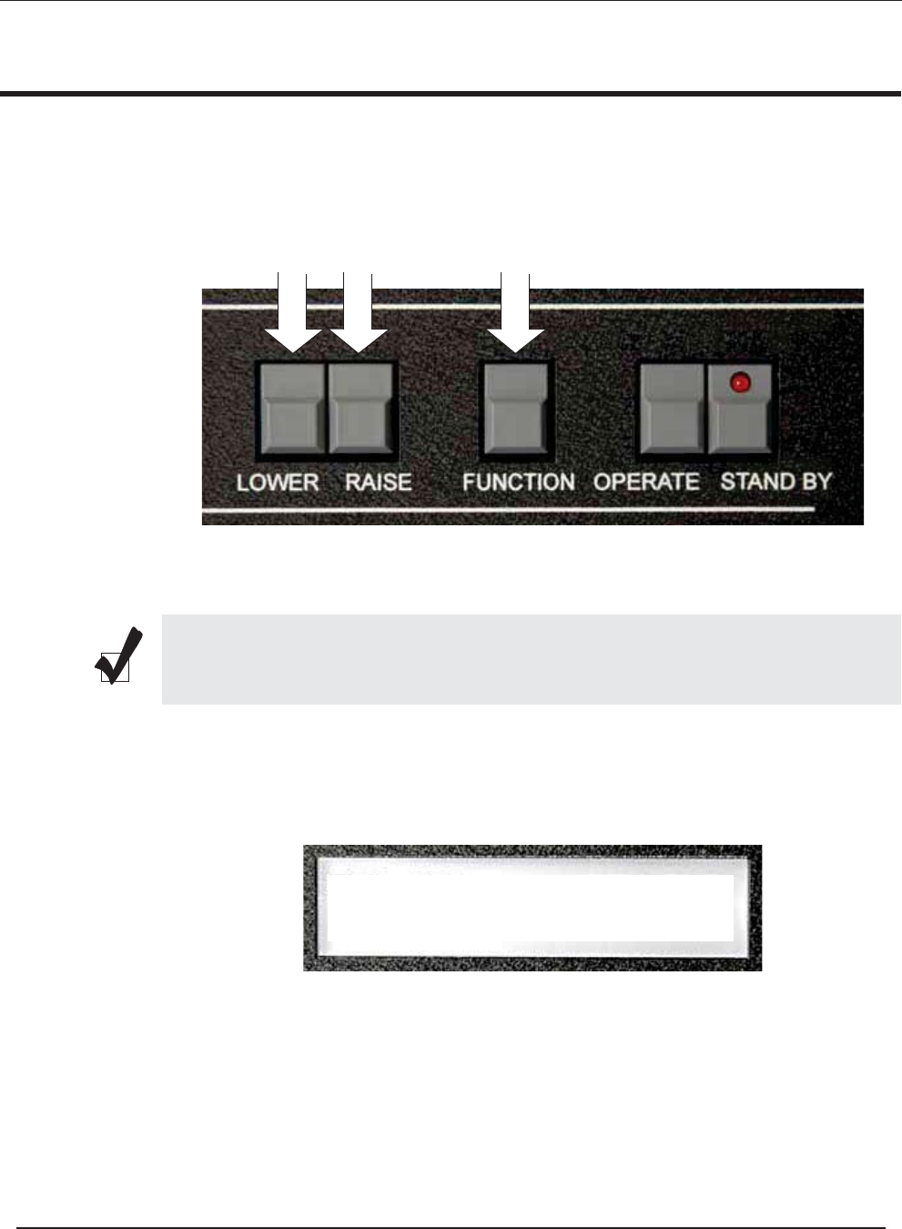
Standby Key
Operate Key
Handle
Meter Function Key
Lower Key Raise Key
LCD Display
Handle
Forward & Reverse RF Power
Deviation
Final Output Volts & Amperes
ES Series Operating Manual and User Guide
PTEKTM
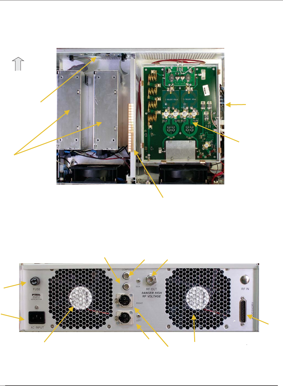
Major internal components of the FM500ES can be seen in the open top view (cover
removed) displayed in Figure 1-4 ( A). Features on the FM500ES rear panel are
shown in Figure 1-4 (B).
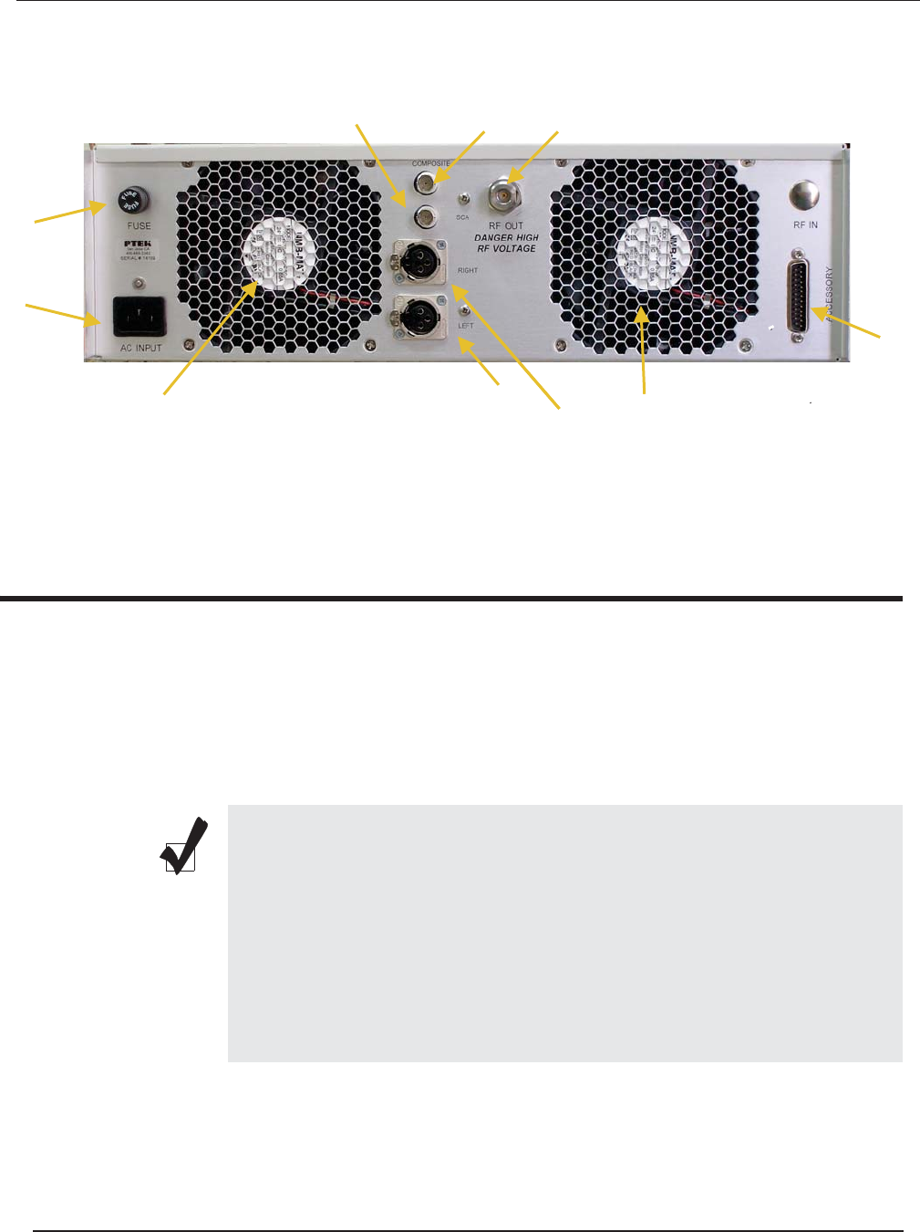
Figure 1-4. FM500ES Open Top View (A) and Rear Panel (B)
AC Power Supplies (2)
AFM500ES Top View (Cover Off)
BFM500ES Rear Panel
Accessory Port
Cooling Fan
RF Output
Fuse (10A)
AC Input
Balanced Audio (Left Stereo Input)
Balanced Audio (Right Stereo or Mono)
SCA Input
Front
Composite Input
High power amplifier
and Harmonic Filter
Control and
Metering Board Control Board
Exciter Board
Cooling Fan
ES Series Operating Manual and User Guide
PTEKTM

1.2 Specifications
1.2.1 General
Table 1-1 lists general specifications for the FM500ES.
Table 1-1. FM500ES General Specifications
Parameter Description
Dimensions z5.25” (3RU) high
z17” (43.2 cm) wide (19” including the front panel)
z13.75” (34.9 cm) deep (including the front panel and rear protective flanges;
the chassis body itself is 13” deep)
Weight Total shipping weight is under 33.5 pounds (15.2 kg) and includes the following:
zChassis = under 24 pounds (10.9 kg), including two AC power supplies
zAdd 8.5 pounds (4 kg) for the shipping container and one AC power cord
zThe manual and associated shipping paperwork weigh approximately 1 lb
(0.5 kg)
19” Rack-Mountable
with Slide capability
zLeft and right rack-mount tabs and handles are attached directly to the chas-
sis. Rack-mount slides are optional.
Temperature
Operating:
Non-Operating:
z0°C to +50°C
z–40°C to +70°C
Relative Humidity
Operating:
Non-Operating:
z8% to 90% non-condensing
z5% to 95% non-condensing
Maximum Wet Bulb
Operating:
Non-Operating:
z27°C, non-condensing
z35°C, non-condensing
Altitude
Operating:
Non-Operating
z0 to 10,000 feet above sea level
z0 to 40,000 feet above sea level
ES Series Operating Manual and User Guide
PTEKTM

1.2.2 Electrical
Table 1-2 lists the electrical specifications for the FM500ES.
1.2.2.1 System Power
The FM500ES, Fm300 and FM150 uses two AC power supplies; FM50ES uses one.
Table 1-2. FM500ES Electrical Specifications
Parameter Description
Frequency Range z87.7 MHz to 108 MHz
Audio Input Impedance z600 ohms
Audio Input Level (Composite) z–10 dBm
Audio Input Level R & L Stereo Encoder (optional)z–10 dBm
Frequency Response (Composite) z20 Hz to 15(90) KHz
Pre-Emphasis z50 or 75 uS
Harmonic Distortion z<0.25%max
Signal-to-Noise Ratio z> 80 dB rms
RF Output Impedance z50 ohms
Output Connector zN-type female
RF Power Output z
Harmonic Attenuation z< –70 dB
Power Requirements z88–264 VAC, internally fused
Fuse zMDA 10 Amperes, 250 Volts AC
ES Series Operating Manual and User Guide
PTEKTM

1.2.3 Environmental
1.2.3.1 Shock
The FM500ES is designed to survive an elevated shock environment. All structural
components are welded together, enabling the system to survive a maximum 3-axis
shock load of 5G at 20-msec duration.
1.2.3.2 Electrostatic Discharge
The FM500ES is designed to tolerate electrostatic pulses up to 15 kilovolts (KV)
with no impact on system operation.
1.2.3.3 Noise Level
Typical noise levels emitted by the FM500ES are outlined in Table 1-3. The chassis
is installed with two 60-mm fans mounted side-by-side at the rear of the system. In
addition, each AC power supply has its own cooling fan.
Table 1-3. Typical Noise Levels of the FM500ES
Measured at: 1Meter 2 Meters
Front 66.24 dB 57.57 dB
Rear 61.53 dB 57.93 dB
ES Series Operating Manual and User Guide
PTEKTM

1.3 Packaging and Shipping
The FM500ES FM Stereo Broadcast Transmitter is packaged in a reusable shipping
container. Approximate weight of an empty container and one (1) AC power cord is
9 pounds (4 kg).
The approximate weight of an FM500ES (installed with two power supplies) is
under 15 pounds (6.8 kg).
The approximate weight of a manual and associated shipping paperwork is one (1)
pound (0.5 kg).
Therefore, both the shipping container and a fully installed FM500ES including
power cord, manual, and associated paperwork, weigh under 25 pounds (11.3 kg).
1.3.1 Rack-Mount Slides (Optional)
Rack-Mount slides (optional) can be installed on each side of the FM500ES for the
purpose of sliding the unit easily in and out of a 19” rack using the convenient front
handles. Rack-mount slides should be ordered at the time of purchase.
To learn how to install rack-mount slides, refer to Appendix B, “Rack-Mount Slide
Installation”, on page B-1.
ES Series Operating Manual and User Guide
PTEKTM

ES Series Operating Manual and User Guide
PTEKTM
2FM150ES
2
Installation
2.1 Installation Procedures
There are no operator serviceable parts inside the FM500ES; therefore, replacement,
inspection, or adjustment of internal components within the FM500ES requires ser-
vice by a PTEK technician only. DO NOT REMOVE THE TOP PROTECTIVE
COVER OF THE FM500ES CHASSIS (see following Warning).
Caution: Use industry-standard ESD grounding techniques when handling all
components. Wear an antistatic wrist strap and use an ESD-protected mat. Store
ESD-sensitive components in antistatic bags before placing them on any surface.
Handle all IC cards by the front panel or edges only.
Warning: Removal of the top protective cover of the FM500ES by anyone other
than an authorized PTEK technician will void the product warranty.
Installation
Section
Chapter
ES Series Operating Manual and User Guide
PTEKTM

2.2 Removing the Protective Top Cover
Open the FM500ES FM Stereo Broadcast Transmitter as follows:
1. Remove the protective top cover of the FM500ES by loosening the two Phil-
lips screws on each side of the chassis (see Figure 2-1).
2. Store the cover and screws in a safe place until replaced.
Warning: Make sure that the AC power cord is removed from the AC input con-
nector on the rear of the FM500ES before removing the protective top cover.
Figure 2-1. FM500ES Right-Side Top Cover Phillips Screws
Phillips Screws (4)
This side and far side
ES Series Operating Manual and User Guide ES Series Operating Manual and User Guide
PTEKTM
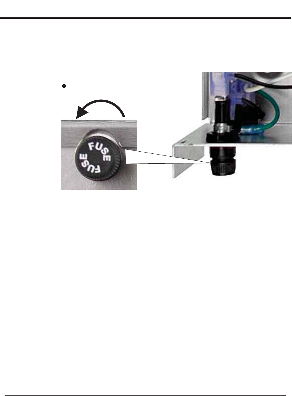
2.4 Changing the Fuse
The FM500ES FM Stereo Broadcast Transmitter contains a fuse rated at MDA 10A,
250V that is installed within an easily removed fuse holder (see Figure 2-4 ).
To remove the fuse, turn the cap of the fuse holder (located at the rear of the chassis)
counterclockwise until it can be removed from the fuse holder body. Pull the fuse
from the cap and replace it with a fuse of the same value.
Figure 2-4. Remove Fuse Holder to Remove Fuse
Turn counterclockwise
Fuse Holder (Rear View)
to remove fuse holder
Fuse Holder (Top View)
ES Series Operating Manual and User Guide
PTEKTM
2. Remove the air filter (see Figure 2-6), then carefully wash it with mild soap
and water.
3. Check that the exposed air vent holes are unobstructed.
4. After the air filter has been dried, replace it and the front panel. Make sure the
front panel screws are fully tightened.
Figure 2-6. Remove the Exposed Air Filter
Figure 2-7. Make Sure the Air Vent Holes are Unobstructed
Air Filter
Air Vent
2.5 Cleaning the Air Filter
Accessing the air filter requires removing the front panel of the FM500ES.
1. Remove the 4 Phillips screws on the FM500ES front panel (see Figure 2-5 ).
Figure 2-5. Remove the Front Panel Screws to Access the Air Filter
Screw
Screw
Screw
Screw
ES Series Operating Manual and User Guide
PTEKTM

2.6 Rack Mounts
Rack-mount brackets (or flanges)—which are built into the chassis and therefore not
removable—are used to secure the FM500ES chassis to a 19” rack.
Rack-mount slides are used to pull the FM500ES away from the rack for easier
access.
2.6.1 Mounting Brackets
Use the following steps to secure a FM500ES chassis to a 19” rack.
1. With the help of a second person, carefully insert the FM500ES chassis into
the 19” rack (see Figure 2-8 ).
2. Using four 10-32 screws with corresponding lock washers and nuts,
attach the FM500ES chassis to the 19” rack through the four mounding holes
of the mounting brackets.
Figure 2-8. Left and Right Rack-Mount Brackets
19” Rack
Right
Bracket
Mounting
Left
Bracket
Mounting
Caution: Make sure to tighten each mounting screw to assure that the
FM500ES chassis is firmly installed onto the 19” rack.
ES Series Operating Manual and User Guide
PTEKTM

2.6.2 Rack-Mount Slides (Optional)
Rack-Mount Slides can be mounted on each side of the FM500ES FM Stereo Broad-
cast Transmitter for the purpose of sliding the unit inand out of a rack. Mounting
slides are optional and should be ordered at the time your system is purchased.
To learn how to install rack-mount slides, refer to Appendix B, “Rack-Mount Slide
Installation”.
Caution: Any screws used to mount a slide to a FM500ES chassis must not exceed
a length of 3/8” to prevent excessive penetration of the chassis.
ES Series Operating Manual and User Guide
PTEKTM

2FM150ES
3
Operation
This chapter describes:
• How to set up the FM500ES system to begin operation
• How to turn the FM500ES on and off
• How to monitor and change the operational settings of the FM500ES
3.1 Set Up the System
To successfully operate the FM500ES FM Stereo Broadcast Tran smitter, an antenna
(or power amplifier) and an audio source must first be connected to the system, as
outlined in the following steps:
1. Connect the antenna or power amplifier input to the RF output connector on
the rear panel of the FM500ES (see Figure 3-1 on page 3-2).
2. Connect the audio input to one of the following connectors the rear panel:
• Composite Input (ensure the Stereo encoder is disabled)
• Balanced Mono Input
• Balanced Stereo Left and Right (if equipped with stereo encoder)
Operation
Section
Chapter
ES Series Operating Manual and User Guide
PTEKTM
3.2 Power Up the System
1. On the rear of the FM500ES, plug an AC power cord (shipped with each unit)
into the AC power socket (see Figure 3-2 on page 3-3).
2. Plug the other end of the AC power cord into a “live” AC outlet.
3. Make sure the STANDBY key on the fr ont of the FM500ES has turned red
(or the system has begun the startup sequence), thus assuring that the system
has powered on (see Figure 3-3, page 3-3).
Figure 3-1. FM500ES Rear-Panel Connectors
Note: There is no On/Off switch (key) on the FM500ES FM Stereo
Broadcast Transmitter. As soon as power is introduced to the system
through an AC power cord attached to a “live AC outlet, if the system was
powered off while in Standby mode, the system will again enter Stand-
by mode and the light on the STANDBY key on the front of the FM500ES
will turn red .
If the system was powered off while not in Standby mode, it will begin the
startup sequence described in the section “Startup Sequence” on page 3-4.
Accessory Port
Cooling Fan
RF Output
Fuse (10A)
AC Input
Balanced Audio (Left Stereo Input)
Balanced Audio (Right Stereo or Mono)
SCA Input Composite Input
Cooling Fan
ES Series Operating Manual and User Guide
PTEKTM
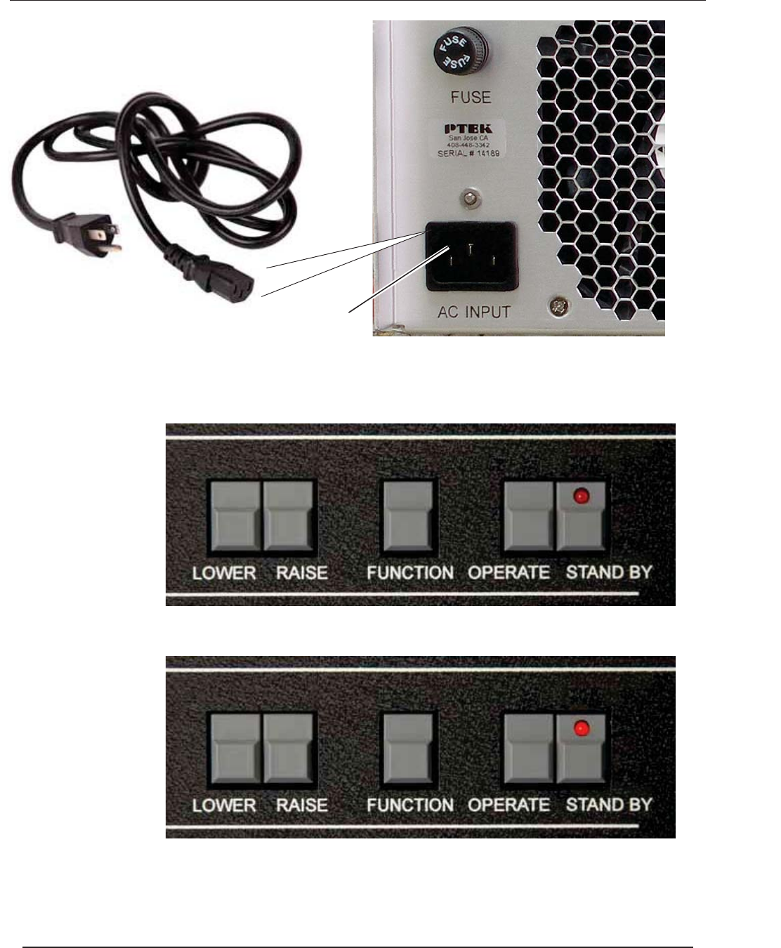
Figure 3-2. Plug the Power Cord into the FM500ES AC Power Socket
Figure 3-3. After Power has been Applied to the FM500ES, it enters Standby mode
AC Power Socket
AC Power Cord
Before power is applied to the system, the STANDBY key LED is offA
After power is applied to the system, the STANDBY key LED turns redB
ES Series Operating Manual and User Guide
PTEKTM
3.3 Getting Started
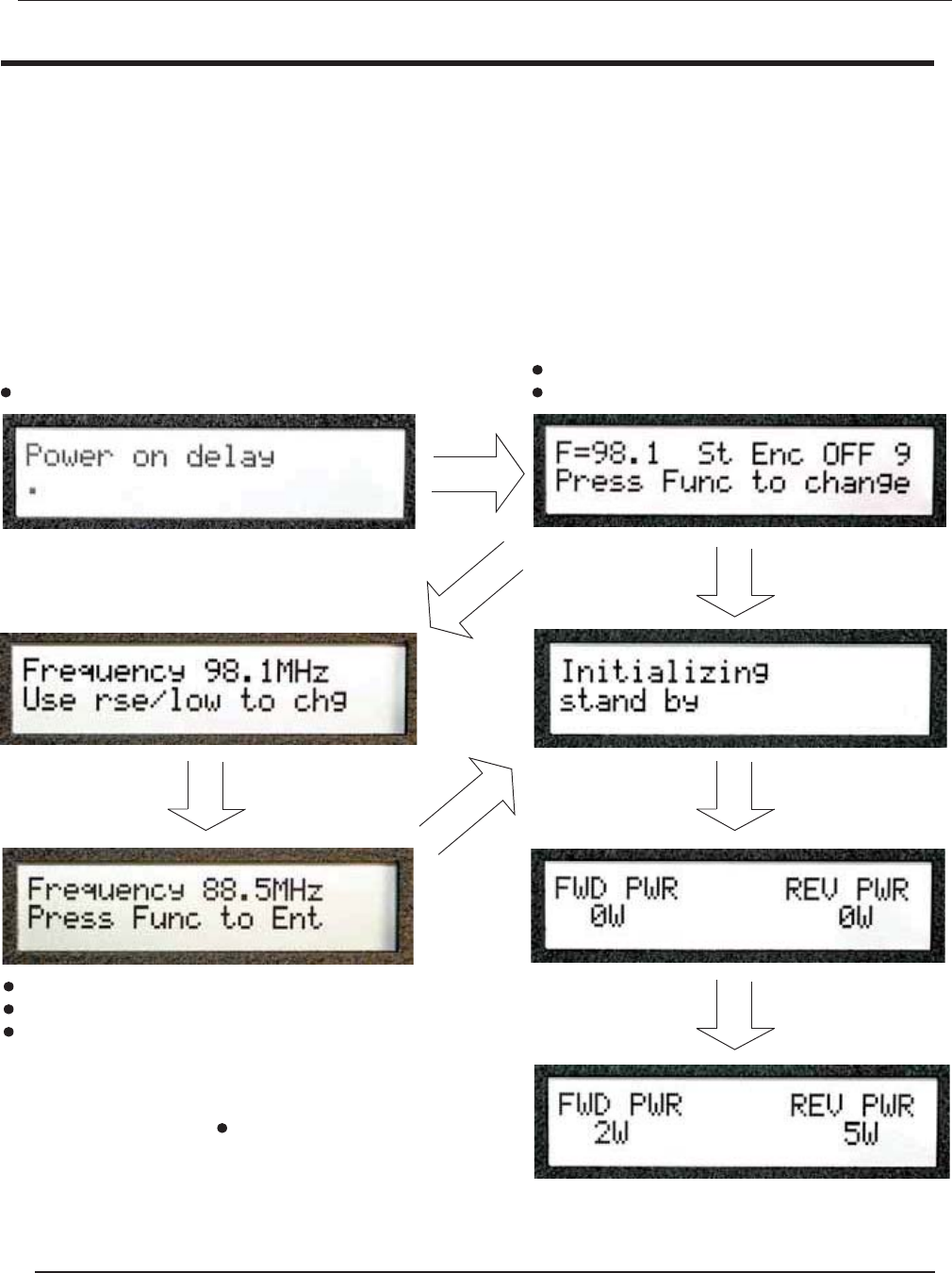
3.3.1 Startup Sequence
1. Press the OPERATE key on th e front of the FM500ES.
2. After the OPERATE key is enabled, the LED display will show the initializ-
ion sequence and display the screens—in order—shown in Figure 3-4.
Figure 3-4. After the OPERATE Key is Pressed, the Startup Sequence Begins
key not pressed
FUNCTION
key pressed
FUNCTION
key pressed
RAISEorLOWER
Initial screen after power on To change frequency, press FUNCTION key
If frequency is correct, wait until timer expires
Press LOWER key to decrease frequency
Press RAISE key to increase frequency
key pressed
FUNCTION
Press FUNCTION key to accept changed frequency
After transmitter frequency is correct,
use the RAISE or LOWER key to set
the power output level
ES Series Operating Manual and User Guide
PTEKTM
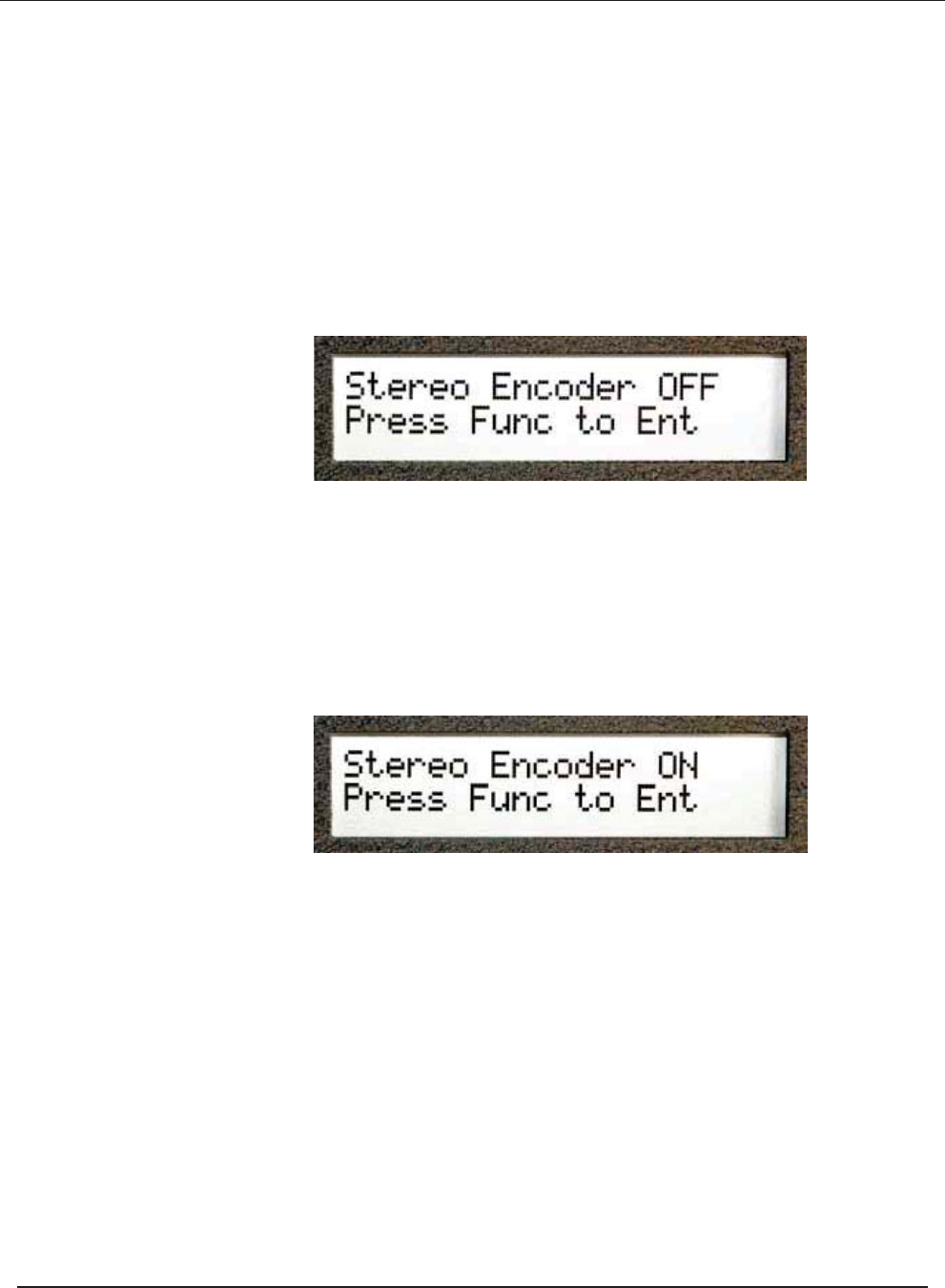
3.3.2 Changing the Stereo Encoder
After changing the frequency in the startup sequence (see previous page), you have
the option of changing the Stereo Encoder setting:
1. If the LCD screen displays the desired setting (Stereo Encoder OFF or ON),
press the FUNCTION key to accept the setting (see Figure 3-5).
2. To change the Stereo Encoder setting, press the RAISE or LOWER key,
which will result in the alternate setting (see Figure 3-6).
Figure 3-5. Stereo Encoder Can be Changed Through the LCD Display
Figure 3-6. Press the RAISE or LOWER key to Change the LCD Display
ES Series Operating Manual and User Guide
PTEKTM
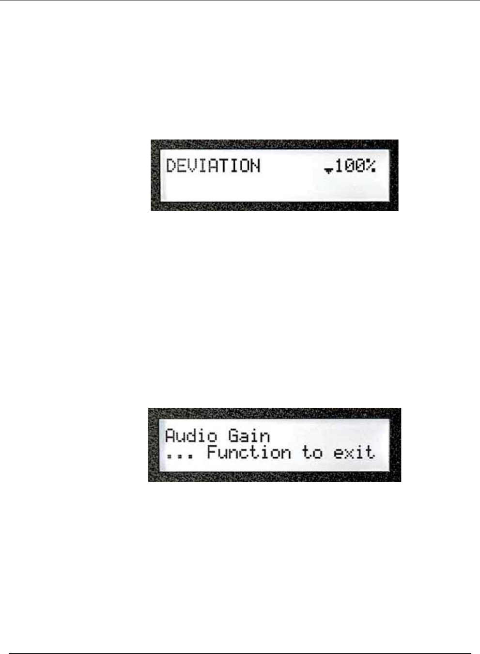
3.3.3 Audio
Audio levels for the FM500ES have already been set and should not need to be
changed. Deviation can be checked by pressing the FUNCTION key until the appro-
priate LCD screen is reached (see Figure 3-7).
When the LCD display is in DEVIATION mode, the maximum deviation should
occasionally reach 100% (indicated by the thick bar). If the 100% level is never
reached or exceeds 100%, the level needs to be adjusted.
The output level from the audio source should be adjusted to give a peak deviation of
75 kHZ (as described above).
If the correct deviation cannot be obtained, the audio gain can be raised or lowered
by pressing the FUNCTION key until the appropriate LCD screen is reached (see
Figure 3-8).
When the AUDIO GAIN screen appears, the value may be raised by pressing the
RAISE key or lowered by pressing the LOWER key until the desired deviation is
reached.
Figure 3-7.
The Deviation Screen is Displayed through the FUNCTION Key
Figure 3-8. Audio Gain Can be Adjusted Through the LCD Display
||||||||||||||||||||||||||||||||||||||||||||||||||| ||
ES Series Operating Manual and User Guide
PTEKTM
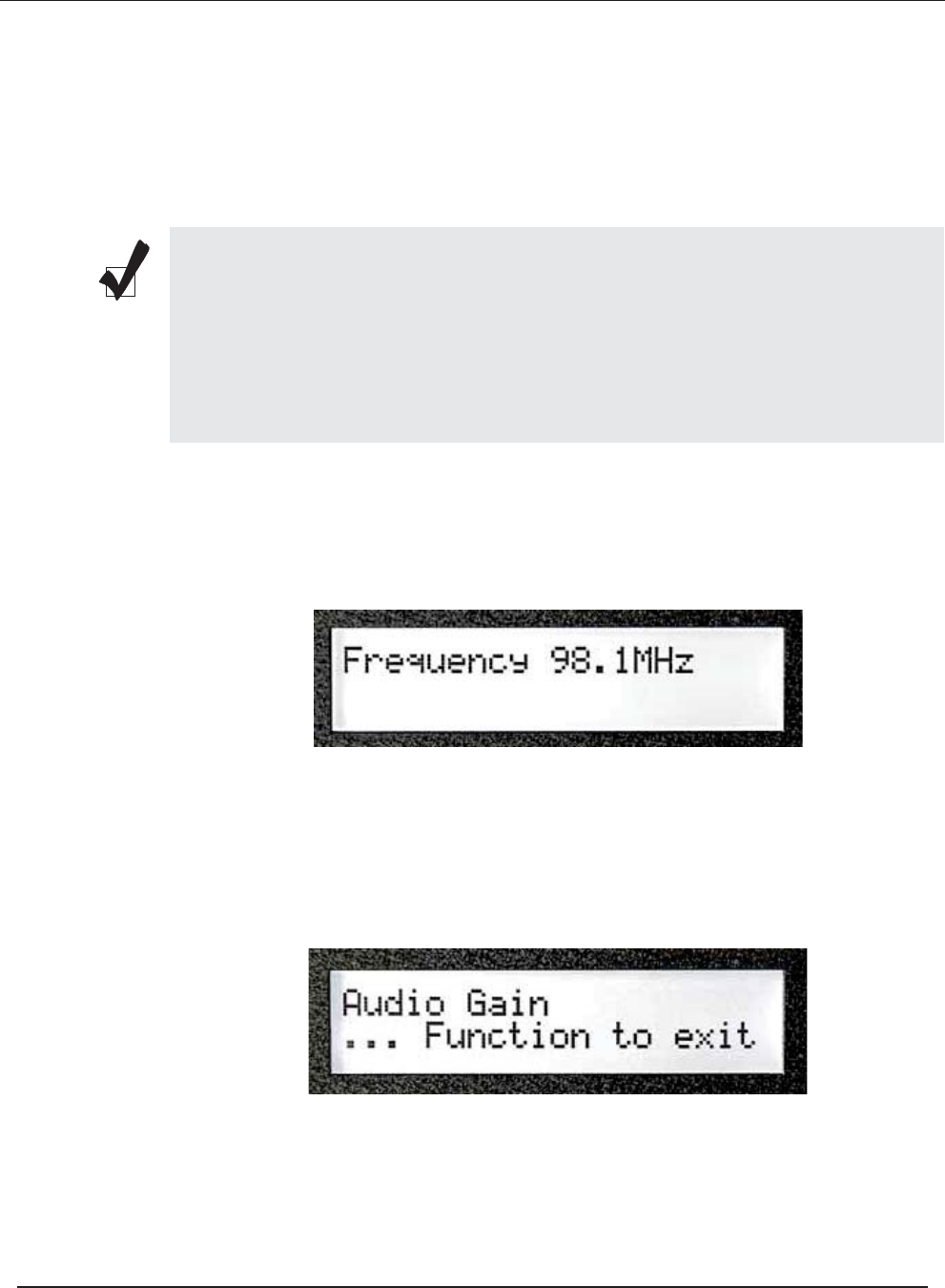
3.3.4 Final Check
Pressing the FUNCTION key rotates the LCD display through the following
screens:
1. After pressing the FUNCTION key on the front of the FM500ES, the operat-
ing frequency will appear on the LCD display (see Figure 3-9 ).
2. Pressing the FUNCTION key again will display the audio gain (see Figure
3-10).
Note: At each screen, pressing the LOWER or RAISE key changes the output
power only. PA VOLTS and PA AMPS is another way of indicating the power
output, accomplished by multiplying the voltage by the amperage (current), then
multiplying the result by the efficiency.
Readings should be recorded weekly to keep track of changes, which may indi-
cate developing problems auch as antenna or coax deterioriation.
Figure 3-9. Press the FUNCTION Key to read Frequency
Figure 3-10. Press the FUNCTION Key to read Audio Gain
ES Series Operating Manual and User Guide
PTEKTM
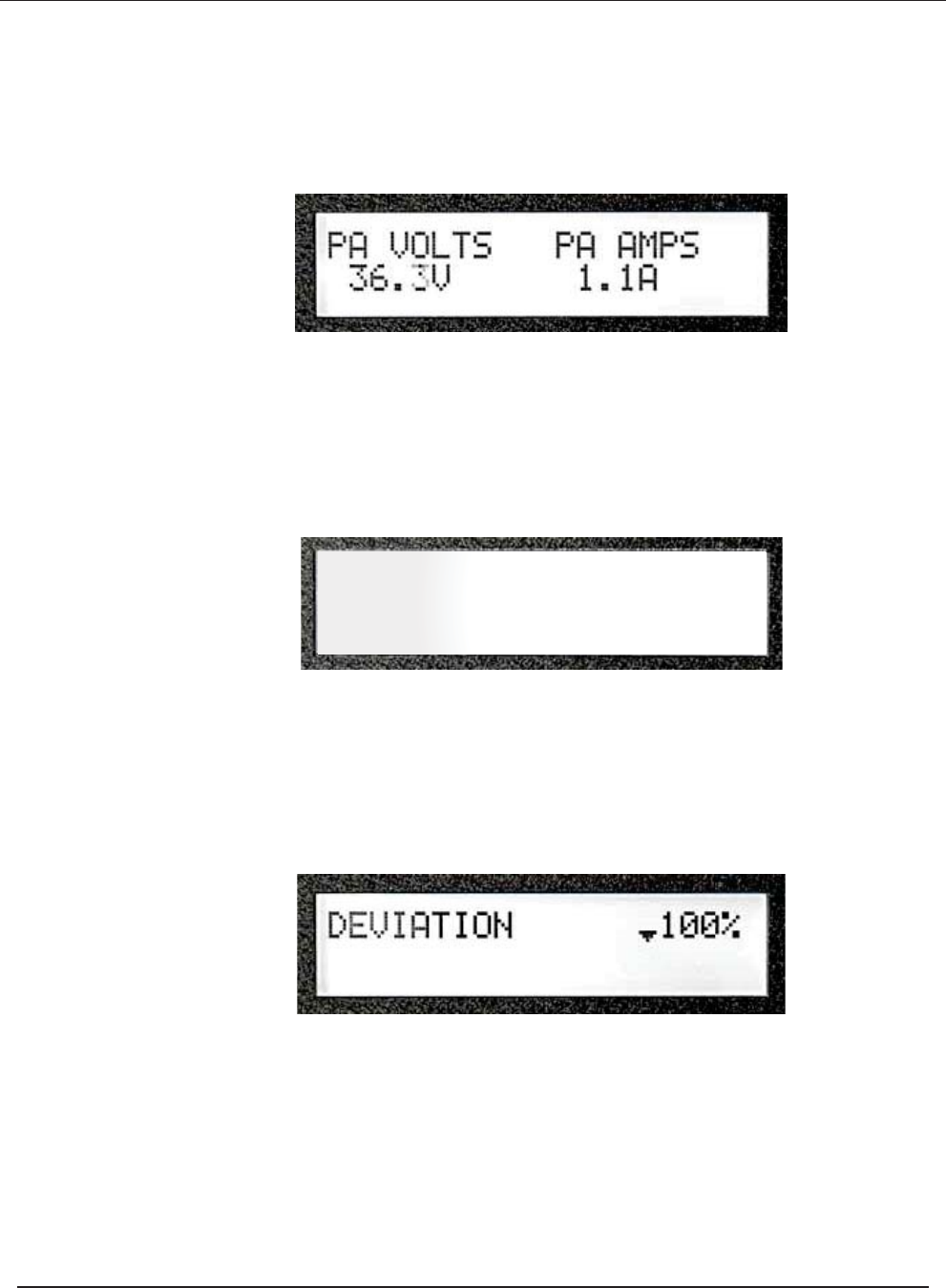
3. Pressing the FUNCTION key again will display the power output (volts mul-
tiplied by amps; see Figure 3-11 ).
4. Pressing the FUNCTION key again results in a screen showing forward pow-
er and reverse power (see Figure 3-12).
5. A final pressing of the FUNCTION key will produce a screen showing devi-
ation (see Figure 3-13).
As already noted, further pressing of the FUNCTION key will rotate the
LCD display through a queue of the same screens.
Figure 3-11. Press the FUNCTION Key to read VOLTS & AMPS
Figure 3-12. Press the FUNCTION Key to read Forward & Reverse Power
Figure 3-13. Press the FUNCTION Key to read Deviation
|||||||||||||||||||||||||||||||||||||||||||| ||
FWD PWR REV PWR
175 0W
ES Series Operating Manual and User Guide
PTEKTM
3.4 Additional Adjustments
The FM500ES offers additional capabilities by pressing the LOWER, RAISE, and
FUNCTION keys simultaneously (see Figure 3-14).
The resulting LCD screens will appear as follows:
1. First,
After a sew seconds, ____________
Press the FUNCTION key to display the next LCD screen.
Figure 3-14. Press LOWER/RAISE/FUNCTION Keys Simultaneously
Note: When pressing LOWER, RAISE, and FUNCTION, the FM500ES cannot
be in STANDBY mode.
Figure 3-15.
Factory setup
ES Series Operating Manual and User Guide
PTEKTM

2.
3.
4.
3.5 Tune Up the Antenna
After the FM500ES is transmitting on the desired frequency (refer to Section 3.3,
“Getting Started,” on page 3-4), check the reverse power, which should be zero.
Anything greater than 5 percent of the forward power (i.e., 5W for a 100W output)
requires attention.
If the reverse power is higher than 5 percent, recheck the antenna tuning instructions.
Figure 3-16.
Figure 3-17.
Set pilot level
PRESS FUNC TO EXIT
Set ref frequency
PRESS FUNC TO EXIT
Use the raise Lower Keys
to adjust
Caution do not change any of these setting
unless you have the proper test equipment
and are able to make the apropriate mea-
surements
ES Series Operating Manual and User Guide
PTEKTM

3.6 Power Down the System
To power down (turn off) the FM500ES FM Stereo Broadcast Transmitter, press the
STANDBY key, then disconnect the AC pow er cord from the AC power socket on
the rear panel of the chassis.
ES Series Operating Manual and User Guide
PTEKTM

ES Series Operating Manual and User Guide
PTEKTM
A
Connector Pinouts
This appendix provides connector pinouts and signal descriptions for the user I/O
connectors that are installed on the FM500ES FM Stereo Broadcast Transmitter rear
I/O Panel (see Figure 1-4, page 1-3, in Chapter 1, "Overview and Specifications").
A.1 Accessory Port
The FM500ES rear I/O Panel provides a 25-pin male DB25 connector as an acces-
sory-port interface. Apinout is provided in Figure A-1; signal descriptions are
defined in Table A-1 on page A-2.
Figure A-1. Accessory Port Pinout
Appendix
ES Series Operating Manual and User Guide
PTEKTM

Table A-1. Accessory Port Pinout Signal Descriptions
Pin Signal Function
1 Forward power DC indication; 2.4V = 150W
2 Final voltage DC indication; V = V/10
3 Output power out of range Hi (10V)
4Not used
5, 6, 18, 19 24V outout (fan supply for combiners)
7Not used
8 Raise; ground to raise the output power
9Not used
10 Not used
11, 12, 23, 24 Ground
13
14 Reverse power DC indication; 2.4V = 150W
15 Output power out of range Lo (10V)
16 Not used
17 Not used
20 Lower; ground to lower the output power
21 Final current DC indication; Full scale = 2.5V
22 Not used
25
Remote on (ground to turn the unit on momentarily only)
Remote off (ground to turn the unit off momentarily only)
ES Series Operating Manual and User Guide
PTEKTM

B
Rack-Mount Slide Installation
An optional set of two rack-mount slides (left side and right side) is available for all
FM500ES FM Stereo Broadcast Transmittersystems, and should be ordered at the
time of purchase. The FM500ES chassis contains two (2) threaded screw holes (see
Figure B-1 on page B-2) on each side to accommodate #10-32 size screws (included
with the rack-mount slide kit).
Dimensions of the screw-hole patterns on the sides of the FM500ES chassis for
installing rack-mount slides are shown in Figure B-2 on page B-3. The required
holes for specialized steel or aluminum slides will have to be measured, drilled, and
tapped before installation.
The rack-mount slide installation kit includes the following items:
a. Two inside slide sections
b. Two outside slide sections
c. Two front (short) slide brackets
d. Two rear (long) slide brackets
e. Assorted screws, washers, and nuts
Follow these steps to install a steel rack-mount slide to the FM500ES chassis:
Caution: Any screws used to mount a slide to a FM500ES chassis must not exceed
a length of 3/8” to prevent excessive penetration of the chassis.
Appendix
ES Series Operating Manual and User Guide
PTEKTM
1. Attach the inside slide section (see Figure B-3 on page B-3) to both sides of
the FM500ES chassis using two #10-32 screws per side (see .
2. Measure the depth of the 19” equipment rack into which the FM500ES system
will be installed (this can vary from 24” to 30”).
3. Using the depth of the equipment rack, adjust and attach the front and rear
slide brackets to the outside slide section using the screws, washers, and nuts
provided with the slide kit.
4. With all slide brackets securely attached to both the right and left outside slide
sections, install both sections to the inside right and inside left of a 19” rack
with two bolts per bracket, making sure there is adequate room for the 2RU
height (3.5”) of a FM500ES system.
5. Carefully insert the FM500ES system into the 19” rack so that the inside
slides on both sides of the chassis travel smoothly into the channels of the out-
side slide sections. Push the system into the rack until the mounting brackets
on the front of the chassis are flush with the front of the rack.
6. Secure the FM500ES system to the 19” rack with two bolts on each side.
Figure B-1. FM500ES Right-Side Rack-Mount Slide Holes
10-32 Threaded Rack-Mount Slide Holes (2)
ES Series Operating Manual and User Guide
PTEKTM

Appendix C Setting the FSK ID
With the unit in the stand-by mode
Press and hold the Raise button; then switch the unit from
Stand-by to operate
FSK ID TIMER
XXXXXX 00
Release the Button when this is displayed
on the LCD display
Pressing the Function Button will increment the curser, pressing raise/lower
will change the character. When you are satisfied with both the CW ID and the
interval timer (which is in Minutes) press the function switch to bring the
curser to the first caracter then turn the unit to stand-by.
To disable the CW ID set the timer to 00.
After this is programmed the unit will send the set CW ID at the programmed
timer interval. With most FM receivers this id will be inaudible.
ES Series Operating Manual and User Guide
PTEKTM