FOXCONN T77H121050 802.11n 1x1 PCIe MINICARD TRANSCEIVER User Manual FT30 En Sch V1 1 Standard 3 2
FOXCONN INTERNATIONAL INC 802.11n 1x1 PCIe MINICARD TRANSCEIVER FT30 En Sch V1 1 Standard 3 2
FOXCONN >
Users Manual
Notebook
User's Manual

Disclaimer:
This manual is the intellectual property of our company. However, we reserve the
right to change product specifications without notice. Information in this document
may change without notice. And our company assumes no liability for damages
incurred directly or indirectly from errors, omissions or discrepancies between the
computer and the manual.
Trademark:
All trademarks are the property of their respective owners.
Version:
User’s Manual V1.1 for Notebook.
P/N: 3A22xxx00-000-G
Symbol description:
Indicating a potential risk of hardware damage or physical injury may exist, and
tells you how to avoid problems.
Refers tips and additional information that can help you to use product better.
WEEE:
The use of this symbol indicates that this product may not be treated as household
waste. By ensuring this product is disposed of correctly, you will help prevent potential
negative consequences for the environment and human health, which could other-
wise be caused by inappropriate waste handling of this product. For more detailed
information about recycling of this product, please contact your local city office, your
household waste disposal service or the shop where you purchased this product.
!
© All rights reserved.
All trade names are registered trademarks of respective manufacturers listed.
All images are for reference only, please refer to the physical product for specific features.
Safety Precautions
The following safety precautions will increase the life of the Notebook. Please follow
allprecautions and instructions. Except as described in the manual, refer all servicing
to qualified personal.
■ Do not place on uneven or unstable work surfaces. Seek servicing if the casing
has been damaged.
■ Do not expose to dirty or dusty environment. And Do not operate during a gas
leak.
■ Do not leave the Notebook on your lap or any part of the body to prevent dis-
comfort or injury from heat exposure.
■ Do not press or touch the display screen. Do not place together with small items
that may scratch or enter the Notebook.
■ The Notebook should only be used in environment with ambient temperature
between 0oC(32oF) and 40oC(104oF).
■ Do not place or drop objects on top.
■ Do not expose to or use near liquidscrainscmoisture or strong magnetic or
electrical fields.
■ Do not carry or cover a Notebook that is powered on with any materials that will
reduce air circulation such as a carrying bag.
■ Do not throw the Notebook in municipal waste. Check local regulations for dis-
posal of electronic products.
■ Wipe the Notebook using a clean cellulose sponge or chamois cloth dampened
with a solution of nonabrasive detergent and a few drops of warm water and
remove any extra moisture with a dry cloth.
■ Risk of explosion if battery is replaced by an incorrect type. Dispose of used bat-
teries according to the instructions.
■ Use only the power cord and batteries indicated in this manual. Do not dispose
of batteries in a fire. They may explode. Check with local codes for possible
special disposal instructions.
FCC Regulations:
■ This device complies with part 15 of the FCC Rules. Operation is subject to the
following two conditions: (1) This device may not cause harmful interference, and (2)
this device must accept any interference received, including interference that may
cause undesired operation.
■ This device has been tested and found to comply with the limits for a Class B
digital device, pursuant to Part 15 of the FCC Rules. These limits are designed to
provide reasonable protection against harmful interference in a residential installation.
This equipment generates, uses and can radiated radio frequency energy and, if not
installed and used in accordance with the instructions, may cause harmful interference
to radio communications. However, there is no guarantee that interference will not
occur in a particular installation If this equipment does cause harmful interference to
radio or television reception, which can be determined by turning the equipment off
and on, the user is encouraged to try to correct the interference by one or more of the
following measures:
- Reorient or relocate the receiving antenna.
- Increase the separation between the equipment and receiver.
- Connect the equipment into an outlet on a circuit different from that to which the
receiver is connected.
- Consult the dealer or an experienced radio/TV technician for help.
Changes or modifications not expressly approved by the party responsible for
compliance could void the user‘s authority to operate the equipment.
■ The antenna(s) used for this transmitter must not be co-located or operating in
conjunction with any other antenna or transmitter.
RF Exposure Information (SAR)
This device meets the government’s requirements for exposure to radio waves.
This device is designed and manufactured not to exceed the emission limits for
exposure to radio frequency (RF) energy set by the Federal Communications
Commission of the U.S. Government.
The exposure standard for wireless devices employs a unit of measurement known
as the Specific Absorption Rate, or SAR. The SAR limit set by the FCC is 1.6W/kg.
*Tests for SAR are conducted using standard operating positions accepted by the FCC
with the device transmitting at its highest certified power level in all tested frequency
bands. Although the SAR is determined at the highest certified power level, the actual
SAR level of the device while operating can be well below the maximum value. This is
because the device is designed to operate at multiple power levels so as to use only
the poser required to reach the network. In general, the closer you are to a wireless
base station antenna, the lower the power output.
The highest SAR value for the device as reported to the FCC when tested for worn
on the body, as described in this user guide, is 0.011 W/kg for WLAN Body SAR.
(Body-worn measurements differ among device models, depending upon available
accessories and FCC requirements.)
While there may be differences between the SAR levels of various devices and at
various positions, they all meet the government requirement.
The FCC has granted an Equipment Authorization for this device with all reported
SAR levels evaluated as in compliance with the FCC RF exposure guidelines.
SAR information on this device is on file with the FCC and can be found under the
Display Grant section of www.fcc.gov/oet/ea/fccid after searching on FCC ID: WXC-
T77H121050.
This Transmitter has been demonstrated co-location compliance requirements
with Bluetooth transmitter. This transmitter must not be co-located or operating in
conjunction with any other antenna or transmitter. This equipment complies with FCC
RF radiation exposure limits set forth for an uncontrolled environment. This device was
tested for typical laptop operations with the device contacted directly to the human
body to the back side of the notebook computer. To maintain compliance with FCC RF
exposure compliance requirements, avoid direct contact to the transmitting antenna
during transmitting.

WiFi Specification
Wireless LAN Standards IEEE 802.11g standard and EWC draft standard
Operating Frequency 2.400 – 2.497 GHz
WLAN Data Rate
802.11g:
54Mbps with fall back of 36, 48, 24, 18, 12, 9, 6Mbps.
802.11b:
11g with fall back rates of 11, 5.5, 2, and 1Mbps
802.11n:
EWC:
HT40:135Mbps with fall back of 121.5, 108, 81,54,
40.5,27, 13.5
HT20:65Mbps with fall back of
58.5,52,39,26,19.5,13,6.5
Transmitter Output Power
802.11b
17dBm+/-2 dBm for all data rate
802.11g
6-24Mbps:+17dBm+/-2dB
36Mbps:+17dBm+/-2dB
48Mbps:+17dBm+/-2dB
54Mbps:+16dBm+/-2dB
802.11n HT20 2GHz
MCS 0: 17dBm+/-2dB
MCS 1: 17dBm+/-2dB
MCS 2: 17dBm+/-2dB
MCS 3: 17dBm+/-2dB
MCS 4: 17dBm+/-2dB
MCS 5: 17dBm+/-2dB
MCS 6: 16dBm+/-2dB
MCS 7: 15dBm+/-2dB
802.11n HT40 2GHz
MCS 0: 14dBm+/-2dB
MCS 1: 14dBm+/-2dB
MCS 2: 14dBm+/-2dB
MCS 3: 14dBm+/-2dB
MCS 4: 14dBm+/-2dB
MCS 5: 14dBm+/-2dB
MCS 6: 13dBm+/-2dB
MCS 7: 12dBm+/-2dB

Radio Technology FHSS
Operating Frequency 2.402GHz ~ 2.480GHz
Channel Numbers 79 channels with 1MHz BW
Transmitter Output Power -6~4dBm output power for BT class 2 operation
Coverage 10m (Varies depending on operating environment)
Receiver Sensitivity -75dBm, BER<0.1%
Maximum Receiver Signal -10dBm
Operating Voltage 3.3V+/-0.3V
Working Temperature
Operating temp: 0 °C to +70 °C (+32 °F to +158 °F)
Non-operating temp: -10 °C to +75°C (+14 °F to
+167 °F)
Interface USB2.0 with 8 pin narrow pitch connector
Bluetooth Specification
Modulation Schemes
802.11g:
64QAM (54Mbps, 48Mbps), 16QAM (36Mbps,
24Mbps),
QPSK (18Mbps, 12Mbps), BPSK (9Mbps, 6Mbps)
802.11b:
CCK (11 Mbps, 5.5Mbps), DQPSK (2 Mbps), DBPSK
(1 Mbps)
EWC:
64QAM(MCS5, MCS6, MCS7) 16QAM(MCS3,
MCS4) QPSK(MCS1,MCS2) BPSK(MCS0)

Table of Contents
Chapter 1 Introduction to Your Notebook
External Appearance .................................................................................... 2
Setting Up Your Computer............................................................................ 7
Touchpad Usage .......................................................................................... 9
Special Function Keys ................................................................................ 11
Configuring a Wireless Network Connection .............................................. 11
Configuring a Bluetooth Connection........................................................... 12
Chapter 2 Install Windows XP in Notebook
Install Windows XP system in AHCI mode ................................................. 14
Install Windows XP system in IDE mode .................................................. 21
Chapter 3 Install Windows 7 in Notebook
Setting BIOS and Install a new Windows 7 system.................................... 25
Install Drivers in Windows 7 ....................................................................... 28
Chapter 4 Recovery of Windows XP and Windows 7 System .............. 30
Chapter 5 Introduction to the Linux System
Overview .................................................................................................... 34
Recovery of Linux system .......................................................................... 35

■ External Appearance
■ Setting Up Your Computer
■ Touchpad Usage
■ Special Function Keys
■ Configuring a Wireless Network Connection
■ Configuring a Bluetooth Connection
Introduction to Your
Notebook
1
Notebook
2
1
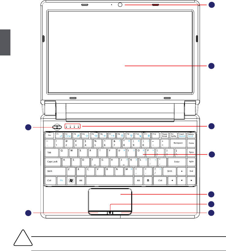
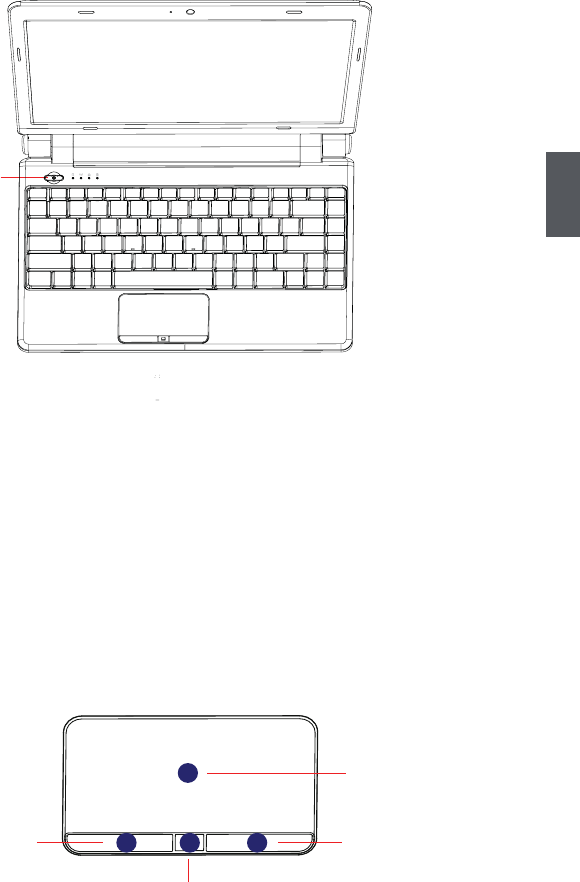
1-1 External Appearance
Refer to the diagram below to identify the components on every side of the Notebook.
1. Top View
!Your Notebook keyboard may vary depending on the country/region of purchase.
1
2
3
5
6
8
9
4
7
3
1
No. Item Description
1 Web Camera Records videos or take photos
2 LCD LED backlight panel
3 Power Button Button for turning the computer's power on/off
● Glowing blue when the Notebook power is turned
on.
● Blinking blue when the Notebook is entering
suspend mode.
4 Status Indicators
From left to right:
a. HDD
● Blinking blue when data is written to or read from
the hard disk drive.
b. Wireless LAN
● The indicator glows blue when wireless LAN func-
tion is enabled.
● The indicator is off when wireless LAN function is
disabled.
c. Caps Lock
● Glowing blue when the keyboard is in Caps-lock
mode.
d. Battery
● Glowing blue when the battery is being charged.
● Blinking blue when the battery is in low battery
status.
● The indicator goes out when the battery is fully
charged.
5 Keyboard Input device used for controlling the Notebook's
various functions
6 Touchpad Works the same way as a mouse and is used for
controlling the computer cursor
7 Left Touchpad Button Works the same way as the left mouse button
8 Touchpad Lock Button Press the button to lock or unlock the touchpad
9 Right Touchpad Button Works the same way as the right mouse button
4
1
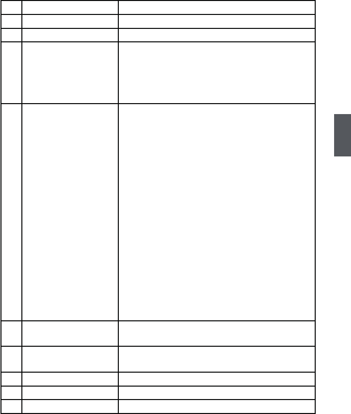
No. Item Description
1 Battery Pack Replaceable battery pack that serves as Notebook's power
supply
2SIM Card Slot
(Optional)
To insert the SIM card into the slot and make sure that the gold
pins of SIM card are downward.
1
2. Rear View
2
!Please do not insert or pull out the SIM card when power-on, otherwise the data
may lose or the card would be damaged.
5
1
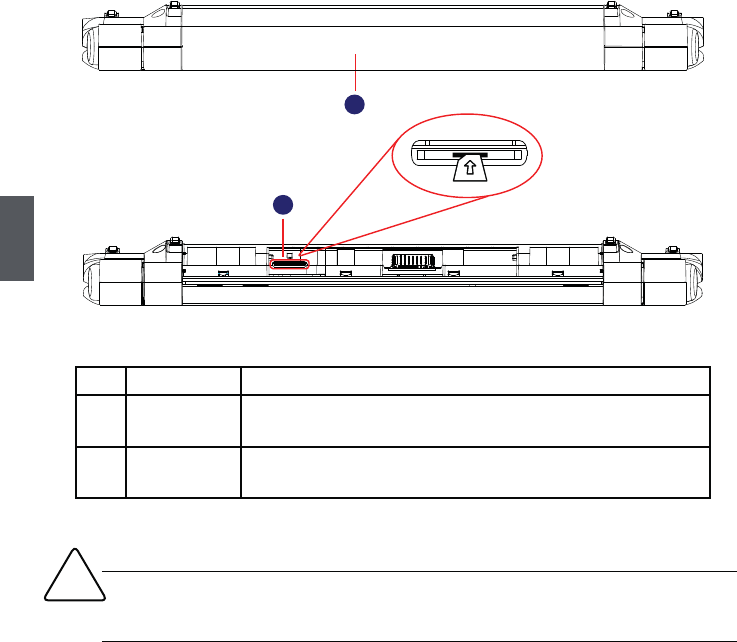
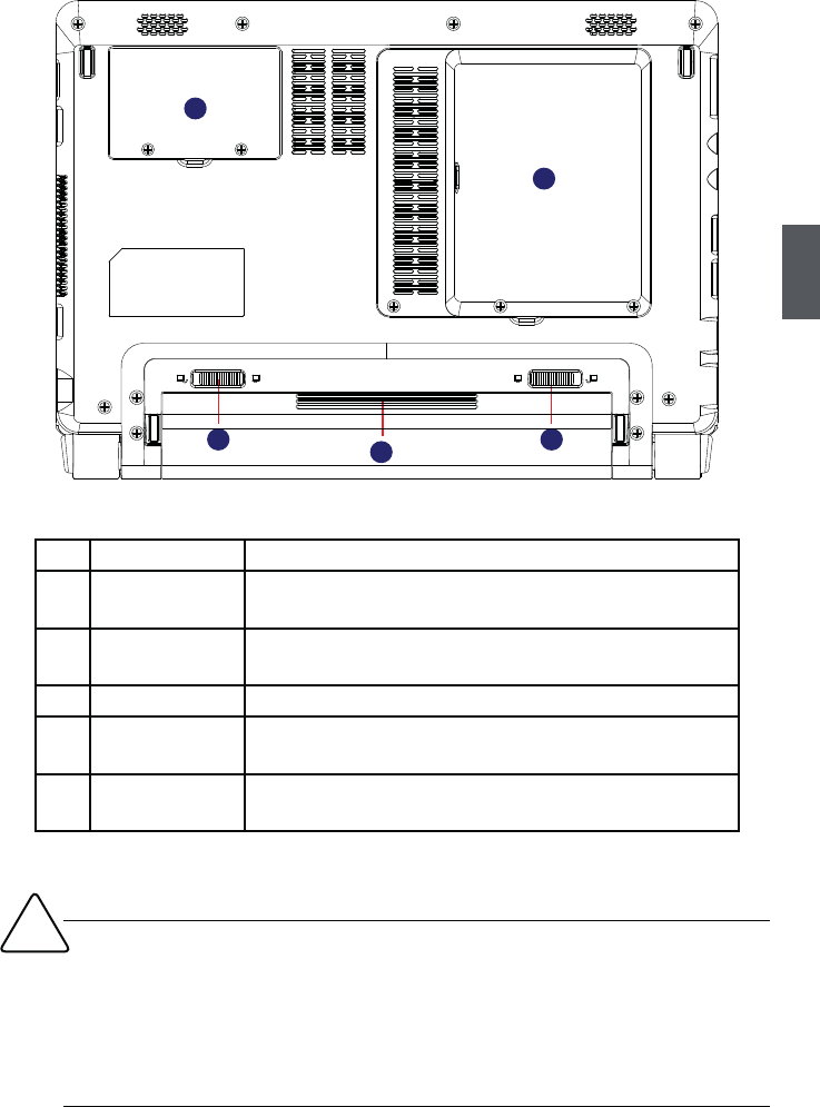
3. Bottom View
No. Item Description
1 Battery Lock Slide inwards to lock the battery in place. Slide outwards to
unlock battery.
2 Battery Pack Replaceable battery pack. Serves as the Notebook's power
supply
3 Battery Latch Push outwards to release battery for removal
4 Hard Disk Cover The Hard Disk Cover protects the internal hardware. Open
to exchange device
5 Memory Cover The cover is to protect the memory from damage. Open to
exchange device
23
4
1
5
!When the computer is running or charging, heat is produced inside the Notebook and
transferred to the back of the chassis by the heat dissipation system for cooling. The
transformer may also produce a lot of heat during normal use as well. The Notebook
and its transformer should therefore not be placed in the lap or on any other body part
for prolonged periods during use. Also avoid placing the Notebook on a soft surface
(e.g. sofa) as it might block the heat vents and interfere with cooling.
6
1
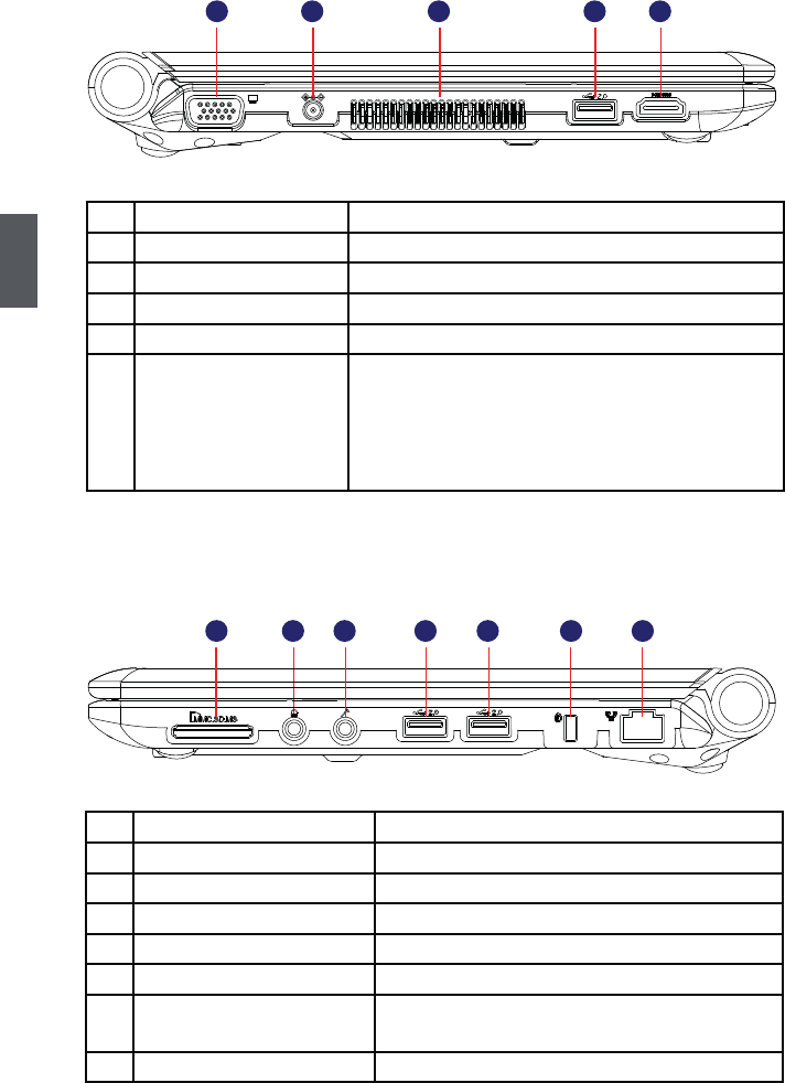
4. Left View
No. Item Description
1 VGA Port Connects to an external display
2 Power Port Connects to the external power supply
3 Vent Notebook's cooling vent
4 USB Port Connects to USB 2.0 device
5 HDMI Port The HDMI(High-Definition Multimedia Interface)
provides an all-digital audio/video interface to
transmit the uncompressed audio/video signals and
is HDCP compliant. Connect the HDMI audio/video
device to the port.
5. Right View
No. Item Description
1 Memory Card Slot Supports MMC/SD/MS memory cards
2 Headphone Connects to external headphone
3 Microphone Connects to external microphone
4 USB Port Connects to USB 2.0 device
5 USB Port Connects to USB 2.0 device
6 Anti-Theft Lock Slot Attach a Kensington security system or a
compatible lock to secure your Notebook
7 Network Port Standard RJ-45 network port
1 2 3 4 5 6 7
12 3 4 5
7
1
1-2 Setting Up Your Computer
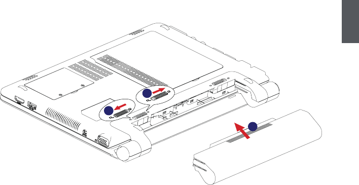
1. Installing/Removing the Battery Pack
The Notebook can be powered by the battery, if you are away from the office and no
power socket is available, use the battery instead.
Installing the Battery Pack
Step 1: Push the “Battery Lock” outwards to unlock position as shown in the figure.
Step 2: Push the battery pack completely into the battery slot.
Step 3: Push the “Battery Lock” inwards to the lock position to lock the battery in place.
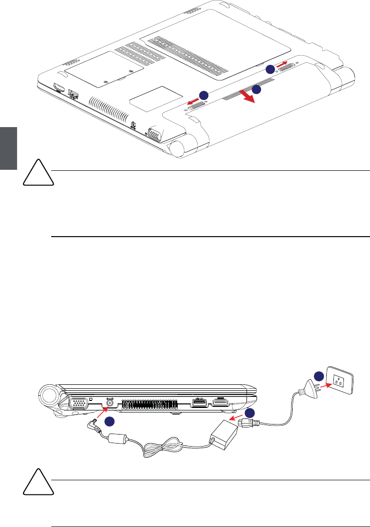
Removing the Battery Pack
Step 1: Unlock the battery by pushing the “Battery Lock” outwards to unlock position
as shown in the figure.
Step 2: Push the “Battery Latch” outwards and hold it in place with your finger, use the
other hand to pull out the battery pack.
3
1
2
8
1
2. Connecting the Power Supply
The AC transformer provides external power source to your notebook and charges the
battery pack at the same time. The AC transformer also has an auto-switching design
that can connect to any 100V AC - 240V AC power outlets.
Step 1. Plug the power cord into the power socket of the AC transformer.
Step 2. Plug the connector of the AC transformer to the DC port of Notebook.
Step 3. Plug the other end of the power cord to a live power outlet.
3
1
2
1
2
3
!■ Do not remove the battery while the Notebook is still running. This may damage the
data on the hard disk.
■ Connect the AC adapter as soon as possible after the battery-low warning appears.
Data will be lost if the battery is to become fully depleted and the computer shuts
down.
!Please use the AC adapter and power cord with the product. Using the wrong adapter
may damage your computer. Once AC adapter or power cord is broken, please consult
professional to resolve the issue.
9
1
3. Startup
Open the screen of your Notebook and turn on the machine by pressing the Power
Button.
Power Button
4. Emergency Shutdown
When the Notebook cannot be shut down through normal means, please press and
hold the Power Button until the Notebook powers off.
1-3 Touchpad Usage
1. Introduction to the Touchpad
The touchpad is a pointing device that senses movement on its surface. This means the
cursor responds as you move your finger across the surface of the touchpad.
Touchpad
Left Button Right Button
Lock Button
23
1
4
10
1
● Move your finger across the touchpad (1) to move the cursor.
● Press the left button(2) and right button(3) located beneath the touchpad to perform
selection and execution functions. These two buttons are similar to the left and
right buttons on a mouse. Tapping on the touchpad is the same as clicking the left
button.
● Press lock button (4) to lock or unlock the touchpad.
Function Left Button (2) Right Button (3) Touchpad (1)
Select Click once. Tap once.
Execute Quickly click twice. Tap twice (at the same speed
as double-clicking a mouse button).
Drag Click and hold, then use
finger on the touchpad to
drag the cursor.
Access context Click once.
menu
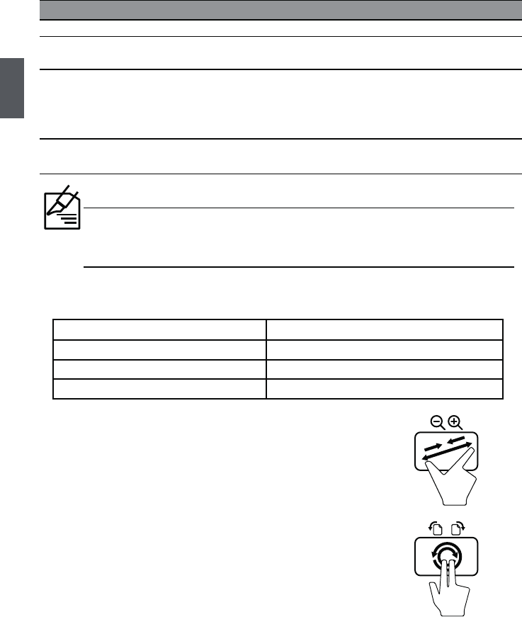
2. Multi-finger Gesture Input
Finger gesture Applications
Two-finger zooming in/out Adobe Reader, Windows Photo Viewer
Two-finger rotating Adobe Reader, Windows Photo Viewer
Two-finger scrolling up/down or left/right Adobe Reader, MS Word, MS Excel
● Two-finger zooming in/out:
Moving two fingertips apart or together on the touchpad to
zoom in or zoom out. This is convenient when viewing photos
or reading documents.
● Two-finger rotating:
Making two fingertips open slightly to draw a concentric circle
on the touchpad to rotate the photo or the document you
are viewing. You can make a clockwise or counterclockwise
rotation based on your needs.
When using the touchpad, keep it and your fingers dry and clean. The touchpad is
sensitive to finger movement; hence, the lighter the touch, the better the response.
Tapping harder will not increase the touchpad’s responsiveness.
Tap twice (at the same speed as
double-clicking a mouse button);
rest your finger on the touchpad on
the second tap and drag the cursor.
11
1
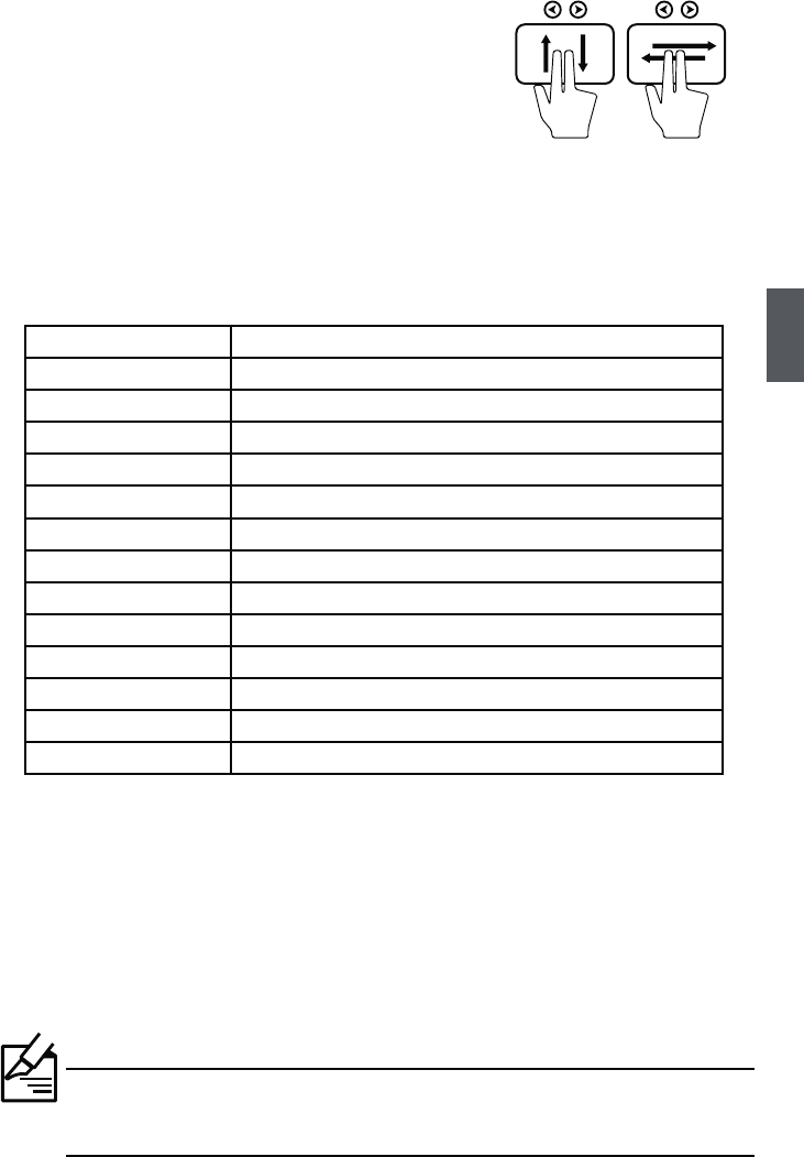
● Two-finger scrolling up/down or left/right:
Making two fingertips open slightly to slide up/down or
left/right on the touchpad to scroll a window up/down or
left/right.
1-4 Special Function Keys
Use the <Fn> key combined on the keyboard to activate, close or set specific functions.
With the help of these keys, user will be able to work efficiently. The following defines
some special function keys on the Notebook.
Function Keys Description
Fn + F1 Enter sleeping mode
Fn + F2 Switches to the external display
Fn + F3 Audio on or off
Fn + F4 Decrease audio volume
Fn + F5 Increase audio volume
Fn + F6 Decrease the display brightness
Fn + F7 Increase the display brightness
Fn + F8 Web Camera on or off
Fn + F9 Wireless LAN on or off
Fn + F11 Bluetooth on or off
Fn + Insert "Number Lock" on or off
Fn + Del "Scroll Lock" on or off
1-5 Configuring a Wireless Network Connection
1. Click the network icon in the Windows® notification area.
2. Select the wireless access point you want to connect to from the list and build the
connection. (When connecting, you may have to enter a password)
3. After a connection has been established, the connection is shown on the list.
Make sure that wireless network is in open state (the status indicator shows
blue), or please press <Fn> + <F9> to enable the WLAN function.
12
1
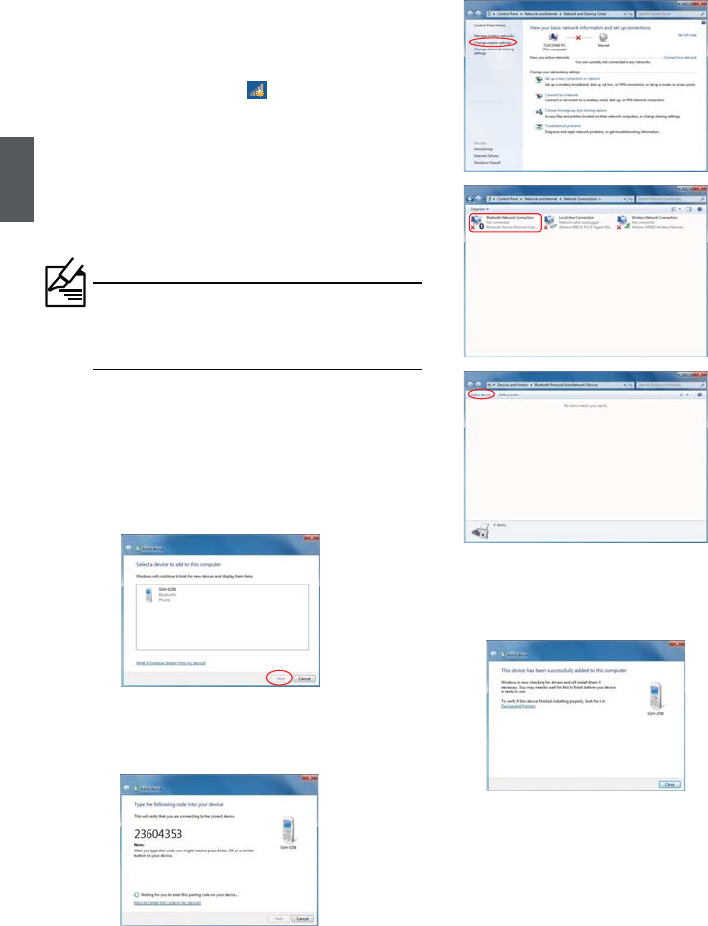
1-6 Configuring a Bluetooth Connection
Bluetooth is a short-range wireless connectivity technology that enables devices
compatible with Bluetooth technology, the distance of 10 meters within the physical
connection and data exchange.
4. Select a Bluetooth-enabled device from the
list and click <Next>.
5. Enter the Bluetooth security code into your
device and start pairing.
6. The paired relationship is successfully
built. Click <Close> to finish the setting.
Follow these steps to create a bluetooth
connection (In Windows 7 system as an
example to illustrate):
1. Click the network icon in the Windows®
notification area, go to <Open Network and
Sharing Center> and then click <Change
adapter settings>.
2. Double click <Bluetooth Network
Connection>.
3. Click <Add a device>to look for new devices.
If there is no <Bluetooth Network
Connection>, please press <Fn> + <F11> to
enable Bluetooth function
1

■ Install Windows XP system in AHCI mode
■ Install Windows XP system in IDE mode
Install Windows XP in
Notebook
Notebook
2
14
2
Install Windows XP System in Notebook
The method to install Windows XP system in the Notebook has the difference because
of the SATA hard disk in BIOS settings, because the SATA hard disk has IDE and AHCI
two kind of modes, so the method to install system also has two kinds.
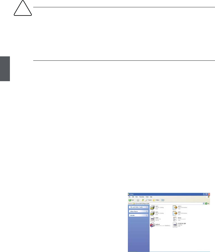
²Create a AHCI Driver Diskette
1. Find a PC, put a diskette into its floppy drive
A:, this diskette will be formatted later. Put
the driver CD into DVD drive.
2. Depending on which platform your system
is, normally, it is a 32-bit XP system. Use
Windows explorer, and go to CD:\Driver\
AHCI\Floppy\32bit, click on RaidTool icon
to start the creation.
2-1 Install Windows XP system in AHCI mode
The default setting of SATA hard disk is AHCI in the Notebook, when you want to install
Windows XP system in AHCI mode, you need to create a AHCI driver floppy diskette
which will be used during Windows XP installation later.
What kinds of hardware and software you need here :
An USB DVD drive, an USB Floppy drive, a Floppy diskette, a Notebook driver CD,
Windows XP Install CD.
Before you continue :
■ Shut down your computer.
■ Connect the DVD drive and Floppy drive to the USB ports of Notebook and connect
the power cord to AC power.
·Please confirm the mode of SATA hard disk before installation of Windows XP
system, and install the system with corresponding method according to the mode.
Otherwise can meet the problem which is unable to install. Please do not change
the mode of SATA hard disk after installation otherwise the system will not work
normally.
·It will short the life of battery pack when you install Windows XP system in IDE
mode of SATA hard disk
!
15
2
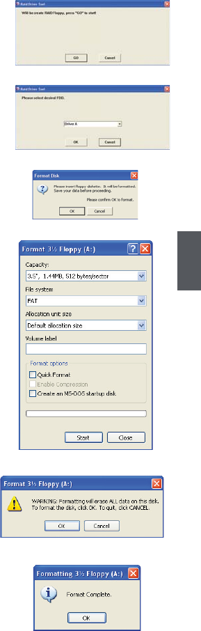
3. Click "GO" to start.
4. Select the desired destination FDD drive. It
can be the default drive A: or any USB FDD.
Click "OK" to continue.
5. Insert a diskette, click "OK" to continue.
6. You can input a volume label for this
diskette, click on "Start" to format.
7. Click on "OK" to go through this warning
message.
8. Format finished. Click "OK" to continue copying
of driver into this diskette.
16
2
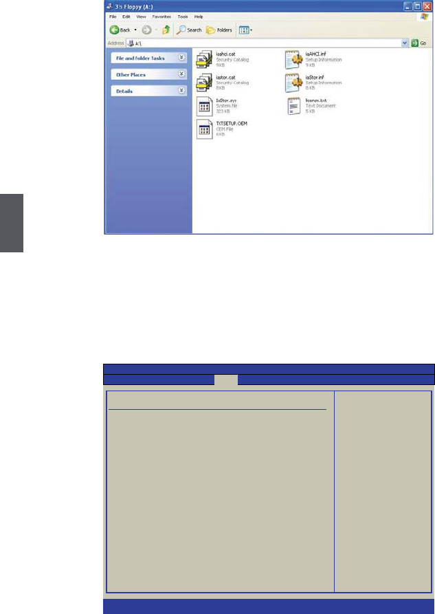
9. Check if the diskette contains the driver files.
²Setting BIOS and Install a New Windows XP
1. Press <Del> to enter BIOS setup during POST, set "1st Boot Device" to "USB :
SONY DVD-ROM D"(DVD drive name) in "Boot" -> "Boot Device Priority" menu,
the figure is as shown below. And then save changes and exit BIOS.
Boot Device Priority Specifies the boot
sequence from the
1st Boot Device [USB : SONY DVD-ROM D] available devices .
2nd Boot Device [HDD : PO-WDC WD2500B]
A device enclosed in
parenthesis has been
disabled in the
corresponding type
menu.
↑↓ ←→ : Move
+/-/ :Change Option
Enter:Select
Esc :Exit
F1 :General help
F2/3 :Change color
F9 : Optimal defaults
F10 : Save and exit
v02.67 (C)Copyright 1985-2009, American Megatrends, Inc.
Boot
BIOS SETUP UTILITY

17
2
2. Insert the Windows XP Install CD into the DVD drive. The computer will reboot, and
it will start installing Windows XP Operating System. Watch the screen carefully,
when the following picture appears, press <F6> key immediately. If you forget to
do this, PC will go to an fatal blue screen, and you may need to reboot the system
again. PC may not respond to your <F6> input immediately, and it keeps loading
files until the next screen displays.
3. After some files are copied to your system, the following picture appears, press <S>
to continue the specific driver installation.
Windows Setup
Press F6 if you need to install a third party SCSI or RAID driver...
Windows Setup
Setup could not determine the type of one or more mass storage devices
installed in your system, or you have chosen to manually specify an adapter.
Currently, Setup will load support for the following mass storage device(s):
<none>
* To specify additional SCSI adapters, CD-ROM drivers, or special
disk controllers for use with Windows, including those for
which you have a device support disk from a mass storage device
manufacturer, press S.
* If you do not have any device support disks from a mass storage
device manufacturer, or do not want to specify additional
mass storage devices for use with Windows, press ENTER.
S=Specify Additional Device ENTER=Continue F3=Exit

18
2
4. It will ask you to insert the driver diskette into your floppy drive. Press <Enter> after
it is done.
5. Press <Enter> to start to select and press "▲" to select the driver "Intel(R) ICH9M-
E/M SATA AHCI Controller".
Windows Setup
Please insert the disk labeled
manufacturer-supplied hardware support disk
into Drive A:
* Press ENTER when ready
Enter=Continue ESC=Cancel F3=Exit
Windows Setup
You have chosen to configure a SCSI Adapter for use with Windows,
using a device support disk provided by an adapter manufacturer.
Select the SCSI Adapter you want from the following list, or press ESC
to return to the previous screen.
ENTER=Select F3=Exit
Intel(R) ICH8M-E/M SATA AHCI Controller
Intel(R) ICH9R/DO/DH SATA AHCI Controller
Intel(R) ICH9M-E/M SATA AHCI Controller
Intel(R) ICH10D/DO SATA AHCI Controller
Intel(R) ICH9M-E/M SATA AHCI Controller

19
2
6. A confirmation message appears to double check if the driver is really what we
wanted, press <Enter> to continue.
7. Insert the Windows XP Install CD into the USB DVD drive. The computer will start
installing Windows XP Operating System. The figure is as shown below:
8. Press <Enter> to continue the installation and press <F8> to agree the Licensing
Agreement. Windows will display the partition of your system. First of all, you had
better press <D> to delete the partition, then you can press <C> to create partitions
as many as you can, assign them C:, D: or E: logical drive name. In this example,
we will create a 50GB partition C: and leave the remaining space as a partition D:.
The figure is as shown below:
Windows Setup
Setup will load support for the following mass storage device(s):
Intel(R) ICH9M-E/M SATA AHCI Controller
* To specify additional SCSI adapters, CD-ROM drivers, or special
disk controllers for use with Windows, including those for
which you have a device support disk from a mass storage device
manufacturer, press S.
* If you do not have any device support disks from a mass storage
device manufacturer, or do not want to specify additional
mass storage devices for use with Windows, press ENTER.
S=Specify Additional Device ENTER=Continue F3=Exit
Windows XP Professional Setup
Welcome to Setup.
This portion of the Setup program prepares Microsoft(R)
Windows(R) XP to run on your computer.
● To set up Windows XP now, press ENTER.
● To repair a Windows XP installation using
Recovery Console, press R.
● To quit Setup without installing Windows XP, press F3.
ENTER=Continue R=Repair F3=Quit
20
2
9. Press <Enter> to install Windows XP. The process will ask you to format hard disk,
copy files...etc, follow the installation steps until the system is installed complete.
² Install drivers in Windows XP
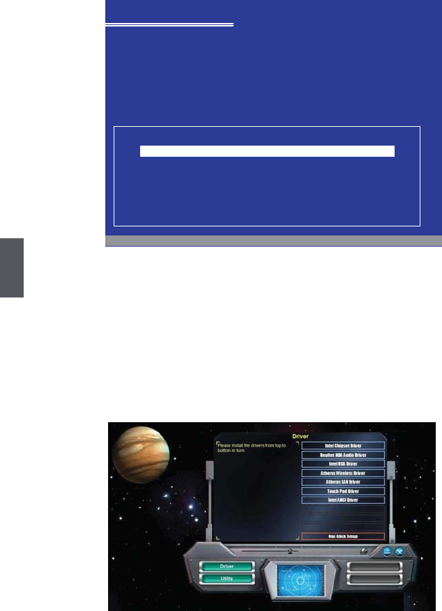
1. After installing Windows XP, you have to install necessary drivers before using the
Notebook. Insert the Notebook driver CD to the USB DVD drive, waiting for a few
seconds, the main menu will be displayed on your Notebook screen.
2. Clicking these options to install all the drivers for your system. You must firstly click
"Intel Chipset Driver" to install and then click "One Click Setup" to install the other
drivers left, or you can click each individual driver to install it manually.
3. After all the drivers are installed, you need to restart your Notebook, then you can
use it.
Windows XP Professional Setup
The following list shows the existing partitions and
unpartitioned space on this computer.
Use the UP ad DOWN ARROW keys to select an item in the list.
● To set up Windows XP on the selected item, press ENTER.
● To create a partition in the unpartitioned space, press C.
● To delete the selected partitions, press D.
114471 MB Disk 0 at id 0 on bus 0 on atapi [MBR]
D: Partition2 [Unknown] 64464 MB < 64463 MB free>
Unpartitioned space 8 MB
Unknown Disk
<There is no disk in this drive.>
Unknown Disk
<There is no disk in this drive.>
ENTER=Install D=Delete Partition F3=Quit
C:Partition1 [NTFS] 49999 MB < 48568 MB free>
21
2
2-2 Install Windows XP system in IDE mode
The default setting of SATA hard disk is AHCI in the Notebook, if you want to install
Windows XP system in IDE mode, please change the mode of SATA hard disk to IDE in
BIOS firstly, otherwise can meet the problem which is unable to install.
What kinds of hardware and software you need here :
An USB DVD drive, a Notebook driver CD, Windows XP Install CD.
Before you continue :
■ Shut down your computer.
■ Connect the DVD drive to an USB port of Notebook and connect the power cord to
AC power.
²Setting BIOS and Install a New Windows XP
1. Power on the Notebook, press <Del> to enter BIOS setup during POST, set
"Configure SATA#1 as" to "IDE " in "Advanced" -> "SATA Configuration" menu, the
figure is as shown below:
2. To set "1st Boot Device" to "USB : SONY DVD-ROM D"(DVD drive name) in
"Boot" -> "Boot Device Priority" menu, the figure is as shown below. And then save
changes and exit BIOS.
SATA Configuration
SATA#1 Configuration [Compatible] IDE
Configure SATA#1 as [IDE] AHCI
AHCI
Settings
► AHCI Port0 [Hard Disk]
↑↓ ←→ : Move
+/-/ :Change Option
Enter:Select
Esc :Exit
F1 :General help
F2/3 :Change color
F9 : Optimal defaults
F10 : Save and exit
v02.67 (C)Copyright 1985-2009, American Megatrends, Inc.
Advanced
BIOS SETUP UTILITY
Options

22
2
Boot Device Priority Specifies the boot
sequence from the
1st Boot Device [USB : SONY DVD-ROM D] available devices .
2nd Boot Device [HDD : PO-WDC WD2500B]
A device enclosed in
parenthesis has been
disabled in the
corresponding type
menu.
↑↓ ←→ : Move
+/-/ :Change Option
Enter:Select
Esc :Exit
F1 :General help
F2/3 :Change color
F9 : Optimal defaults
F10 : Save and exit
v02.67 (C)Copyright 1985-2009, American Megatrends, Inc.
Boot
BIOS SETUP UTILITY
3. Insert the Windows XP Install CD into the USB DVD drive. The computer will reboot,
and it will start installing Windows XP Operating System. The figure is as shown
below:
4. Press <Enter> to continue the installation and press <F8> to agree the Licensing
Agreement. Windows will display the partition of your system. First of all, you had
better press <D> to delete the partition, then you can press <C> to create partitions
as many as you can, assign them C:, D: or E: logical drive name. In this example,
we will create a 50GB partition C: and leave the remaining space as a partition D:.
The figure is as shown below:
Windows XP Professional Setup
Welcome to Setup.
This portion of the Setup program prepares Microsoft(R)
Windows(R) XP to run on your computer.
● To set up Windows XP now, press ENTER.
● To repair a Windows XP installation using
Recovery Console, press R.
● To quit Setup without installing Windows XP, press F3.
ENTER=Continue R=Repair F3=Quit

23
2
5. Press <Enter> to install Windows XP. The process will ask you to format hard disk,
copy files...etc, follow the installation steps until the system is installed completely.
² Install drivers in Windows XP
1. After installing Windows XP, you have to install necessary drivers before using the
Notebook. Insert the Notebook driver CD to the USB DVD drive, waiting for a few
seconds, the main menu will be displayed on your Notebook screen.
2. Clicking these options to install all the drivers for your system. You must firstly click
"Intel Chipset Driver" to install and then click "One Click Setup" to install the other
drivers left, or you can click each individual driver to install it manually.
3. After all the drivers are installed, you need to restart your Notebook, then you can
use it.
Windows XP Professional Setup
The following list shows the existing partitions and
unpartitioned space on this computer.
Use the UP ad DOWN ARROW keys to select an item in the list.
● To set up Windows XP on the selected item, press ENTER.
● To create a partition in the unpartitioned space, press C.
● To delete the selected partitions, press D.
114471 MB Disk 0 at id 0 on bus 0 on atapi [MBR]
D: Partition2 [Unknown] 64464 MB < 64463 MB free>
Unpartitioned space 8 MB
Unknown Disk
<There is no disk in this drive.>
Unknown Disk
<There is no disk in this drive.>
ENTER=Install D=Delete Partition F3=Quit
C:Partition1 [NTFS] 49999 MB < 48568 MB free>

■ Setting BIOS and Install a new Windows 7 system
■ Install Drivers in Windows 7
Install Windows 7 in
Notebook
Notebook
3

25
3
Install Windows 7 in Notebook
Make sure you have these ready:
An USB DVD drive, a Notebook driver CD, Windows 7 Install CD
Before you continue :
■ Shut down your computer
■ Connect the USB DVD drive to an USB port of Notebook and connect the power
cord to AC power
3-1 Setting BIOS and Install a new Windows 7 system
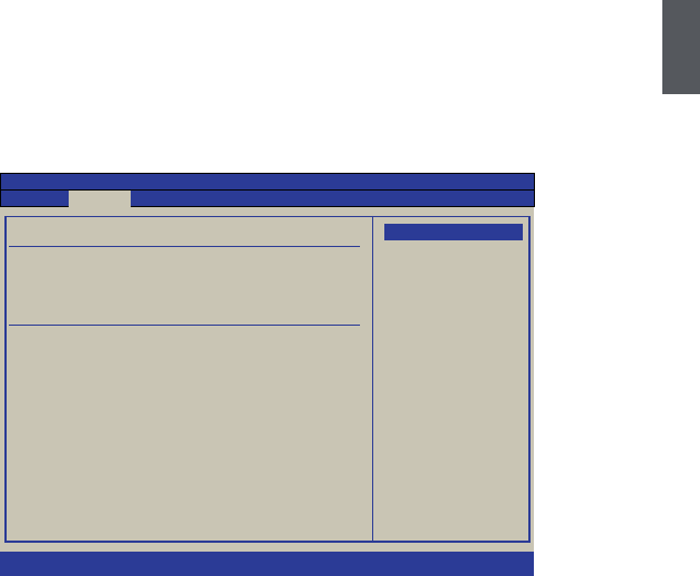
1. Power on your Notebook, then press <Del> to enter BIOS setup during POST, set
"1st Boot Device" to "USB : SONY DVD-ROM D"(DVD drive name) in "Boot" ->
"Boot Device Priority" menu, the figure is as shown below. And then save changes
and exit BIOS.
2. Put the Windows 7 Install CD into the USB DVD drive.
3.
The computer will reboot, and it will start loading files for installing Windows 7 system.
4. After that, it will start Windows and come out a “Install Windows” dialog box to set
the “Language to install”, “Time and current format” and “Keyboard or input
method”. Click “Next” to continue and click “Install now” button to start the setup.
5. When the license terms appears, select to accept and click “Next” to continue.
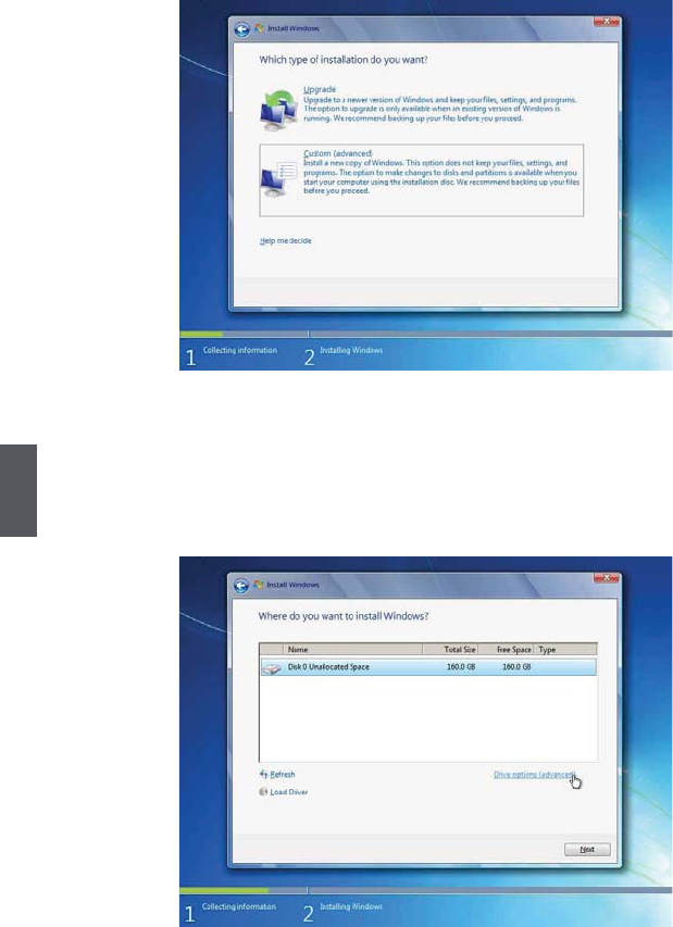
6.
It then asks you to select the installation type. Click “Custom (advanced)” to install a
new copy of Windows.
Boot Device Priority Specifies the boot
sequence from the
1st Boot Device [USB : SONY DVD-ROM D] available devices .
2nd Boot Device [HDD : PO-WDC WD2500B]
A device enclosed in
parenthesis has been
disabled in the
corresponding type
menu.
↑↓ ←→ : Move
+/-/ :Change Option
Enter:Select
Esc :Exit
F1 :General help
F2/3 :Change color
F9 : Optimal defaults
F10 : Save and exit
v02.67 (C)Copyright 1985-2009, American Megatrends, Inc.
Boot
BIOS SETUP UTILITY
26
3
7. The setup will display the hard disk partitions (160GB, in this example) of your
system. If there were other systems (such as Linux) installed previously, you need
select them and click “Drive options (advanced)” -> “Delete” to delete them. When
all partitions are clean, setup will display the biggest size of your hard drive.
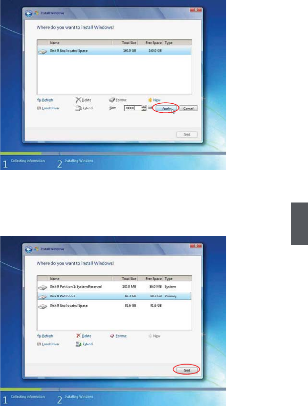
8. In this biggest hard disk size screen, you can click “Drive options (advanced)” ->
“New” to create partitions as you need. In this example, we are creating a 70GB
partition to install Windows, and click “Apply” to continue.
27
3
To ensure that all Windows features work correctly, Windows might create additional
partitions for system files. So you will see a 100MB partition reserved by system after
you create a partition. Select the 70GB partition and click “Next” to continue.
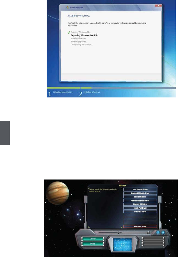
9. From this step we start to install windows 7 into your hard disk. During the process,
your computer will restart several times.
28
3
10. When the installation is complete, setup will prepare your computer for the first
use. Then you can follow steps to select system settings, create an account, set a
password...etc, until the whole process is complete and enter
Windows 7 system
.
3-2 Install Drivers in Windows 7
1. When the Windows 7 is completely installed, you have to install the necessary drivers
before using the Notebook. Take out the Windows 7 Install CD from the USB DVD
drive, and put the driver CD inside. Waiting for a few seconds, the main menu will be
displayed on the screen.
2. Use these options to install all the drivers for your system. You must click "Intel Chipset
Driver" to install it first. After that, you can click "One Click Setup" to install all the other
drivers, or you can click on each individual driver to install it manually.
3. After all the drivers are installed, you need to restart your Notebook, then you can
start using it.

Recovery of Windows XP
and Windows 7 System
Notebook
4

30
4
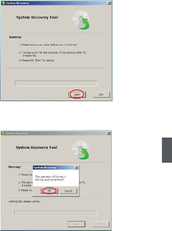
Recovery of Windows XP and Windows 7 System
1. Power on the computer, when the message "Press F3 to Rescue and Recovery"
appears on the top of the screen, press "F3" to enter the recovery interface.
2. System prepares for the recovery after pressing "F3" key.
31
4
3. Recovery begins after clicking "Start" in the following image.
4. When the following image appears, click "OK" to continue.
32
4
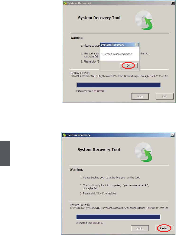
5. Recovery is accomplished when the following image appears, click "OK" to finish it.
6. Now, click "Restart" to reboot the system.

■ Overview
■ Recovery of Linux system
Introduction to the
Linux System
Notebook
5
34
5
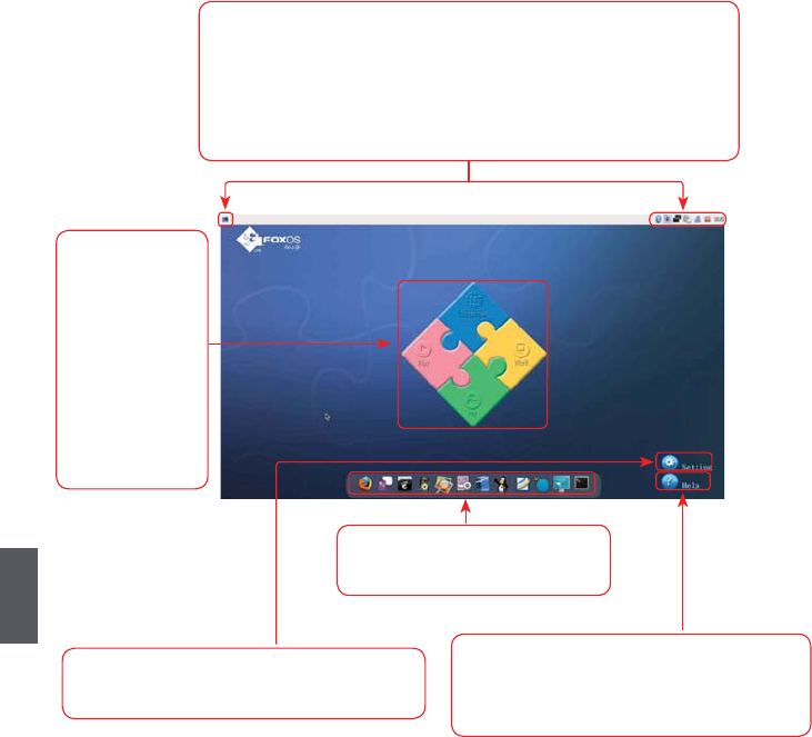
5-1 Overview
After turning on the Notebook, when you log in Linux system, the following screen will
appear:
Click "Setting" to open the page to optimize
the system.
Click "Help" to open the page, please refer
to the content of the page about detailed
description of the system.
From left to right is in turn:
a. Show Desktop icon b. Bluetooth icon(optional)
c. iBus Input Method icon d. Network connection status icon
e. Power icon f. Volume icon
g. Exit icon h. Time icon
The four parts
provide various
applications
to meet the
needs of your
work, life and
entertainment,
detailed refer to
help page.
You can click these icons to go
to the corresponding utilities.
35
5
5-2 Recovery of Linux system
² From DVD to recover system
1Boot from DVD
Power on the computer, insert the system Installation DVD into the DVD drive, press
"F11" to select booting system from the DVD drive.
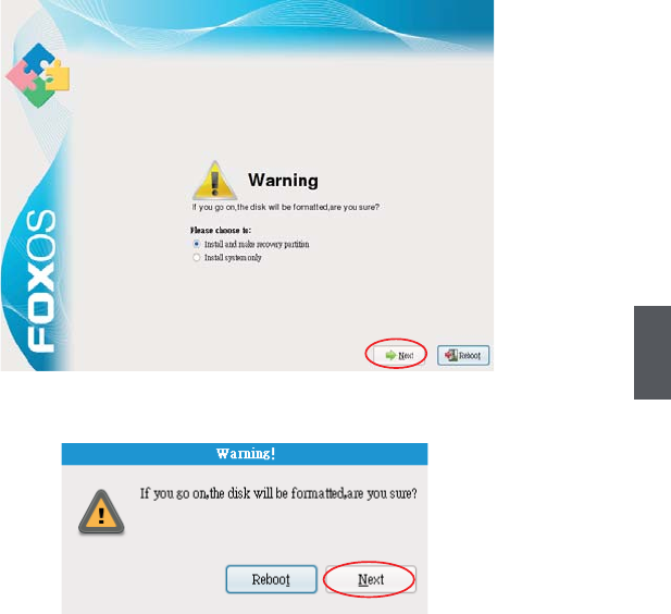
2Select the way of Installation
When the figure as below shows, select "Install and make recovery partition",
the system will be installed and a recovery partition will be made. Or select "Install
system only", the system will be installed without recovery partition, so recover
system from hard disk is impossible.
3Click "Next", the warning box is shown as below:
4 Installing system
Click "Next" to format hard disk and install system. The figure is shown as below:
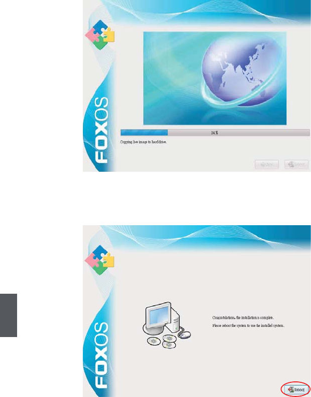
36
5
5 After installing, click "Reboot" to restart the system.
37
5
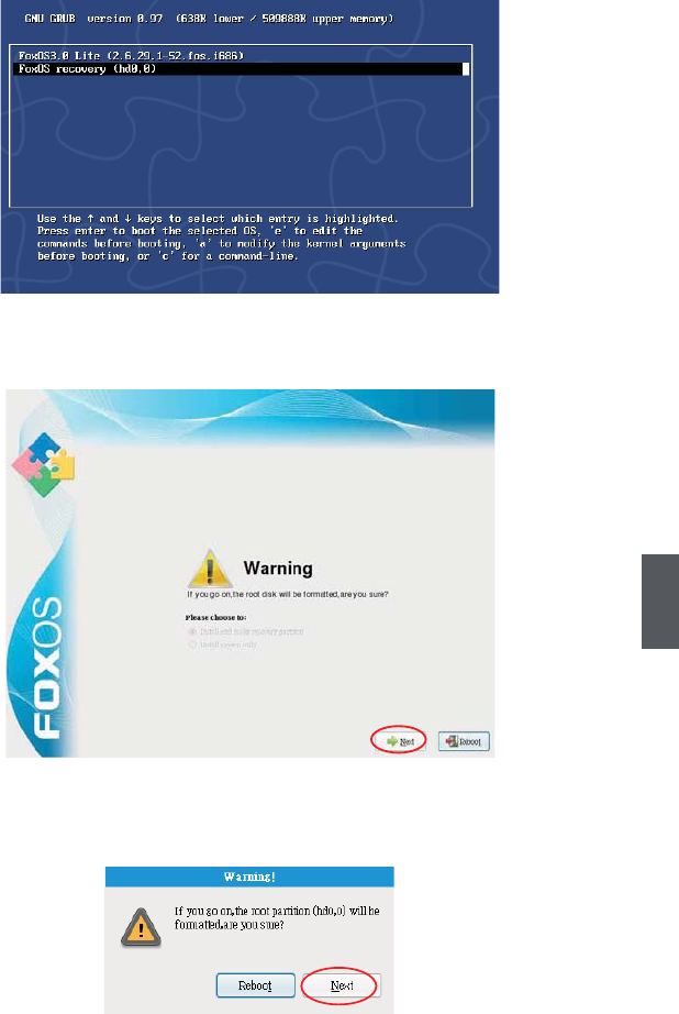
² From hard disk to recover system
1 When you log in, according to the screen suggestion, press any key to enter Grub
interface, the figure is as shown below:
2 Select "FoxOS recovery" item and then press "Enter", the warning box is shown
below:
3Select "Next", system warns the root partition(hd0, 0) will be formatted. The figure is
as shown below:
38
5
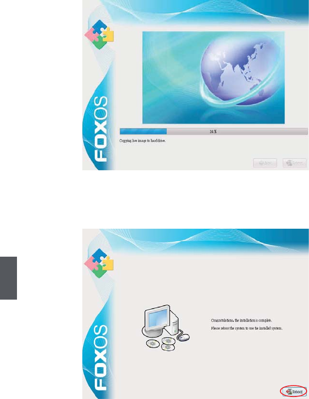
4 Click "Next" to format partition(hd0,0) and recover system from hard disk. The figure
is as shown below:
5 When the process is completed, please reboot the system.The figure is as shown
below: