Fabmatics LF-134-SER-4 LF RFID device User Manual LF 134 SER Low Frequency RFID Reader
Fabmatics GmbH LF RFID device LF 134 SER Low Frequency RFID Reader
UserManual.wiki
>
Fabmatics
>
LF 134 SER 4 User Manual
15_LF-134-SER UserMan
Navigation menu
Upload a User Manual
Namespaces
Wiki Guide
HTML
PDF
Info
Views
User Manual
Discussion / Help
Navigation
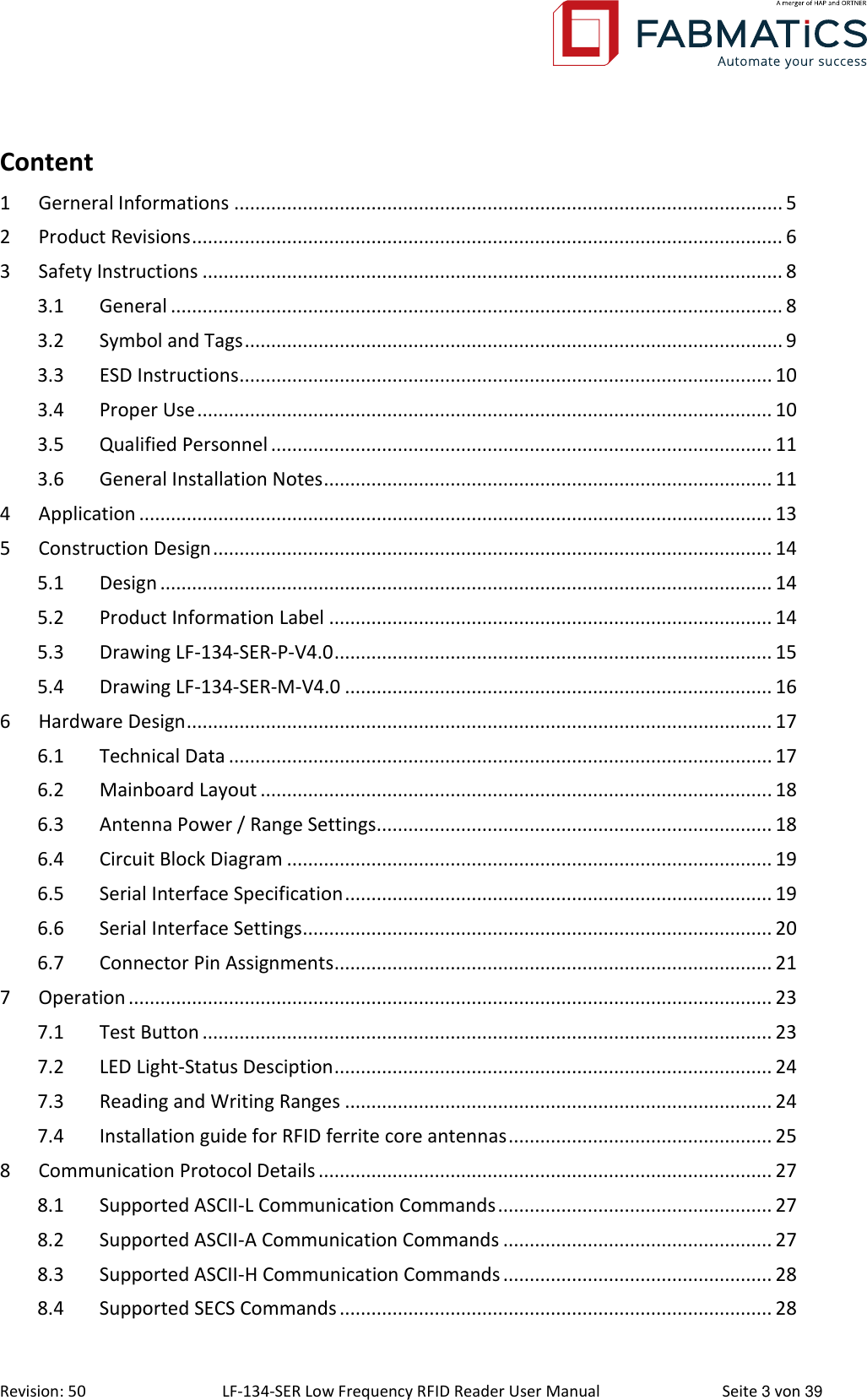
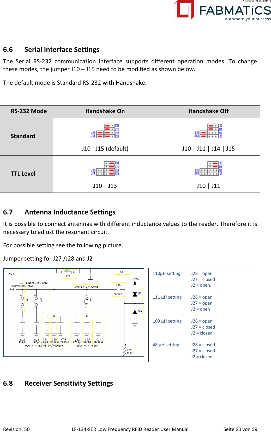
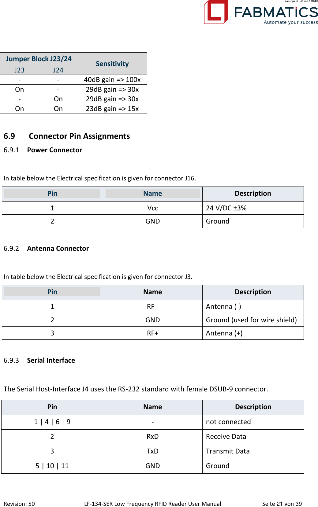
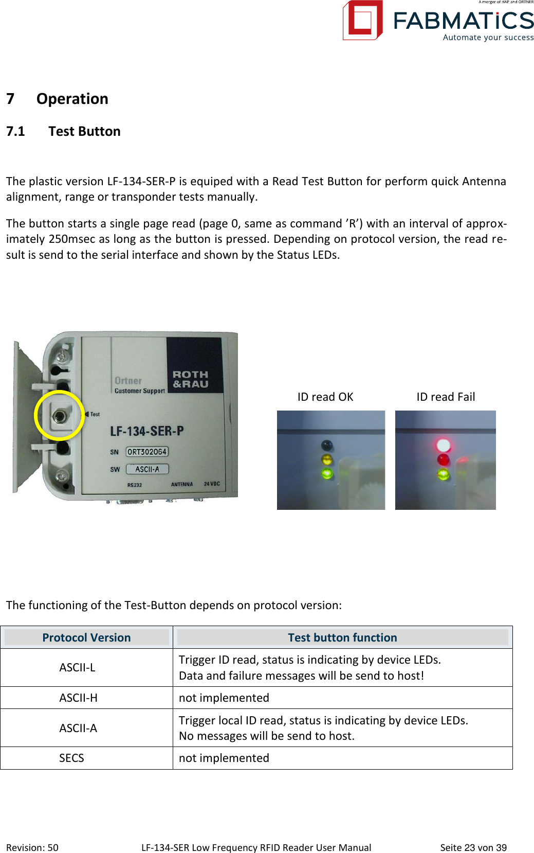
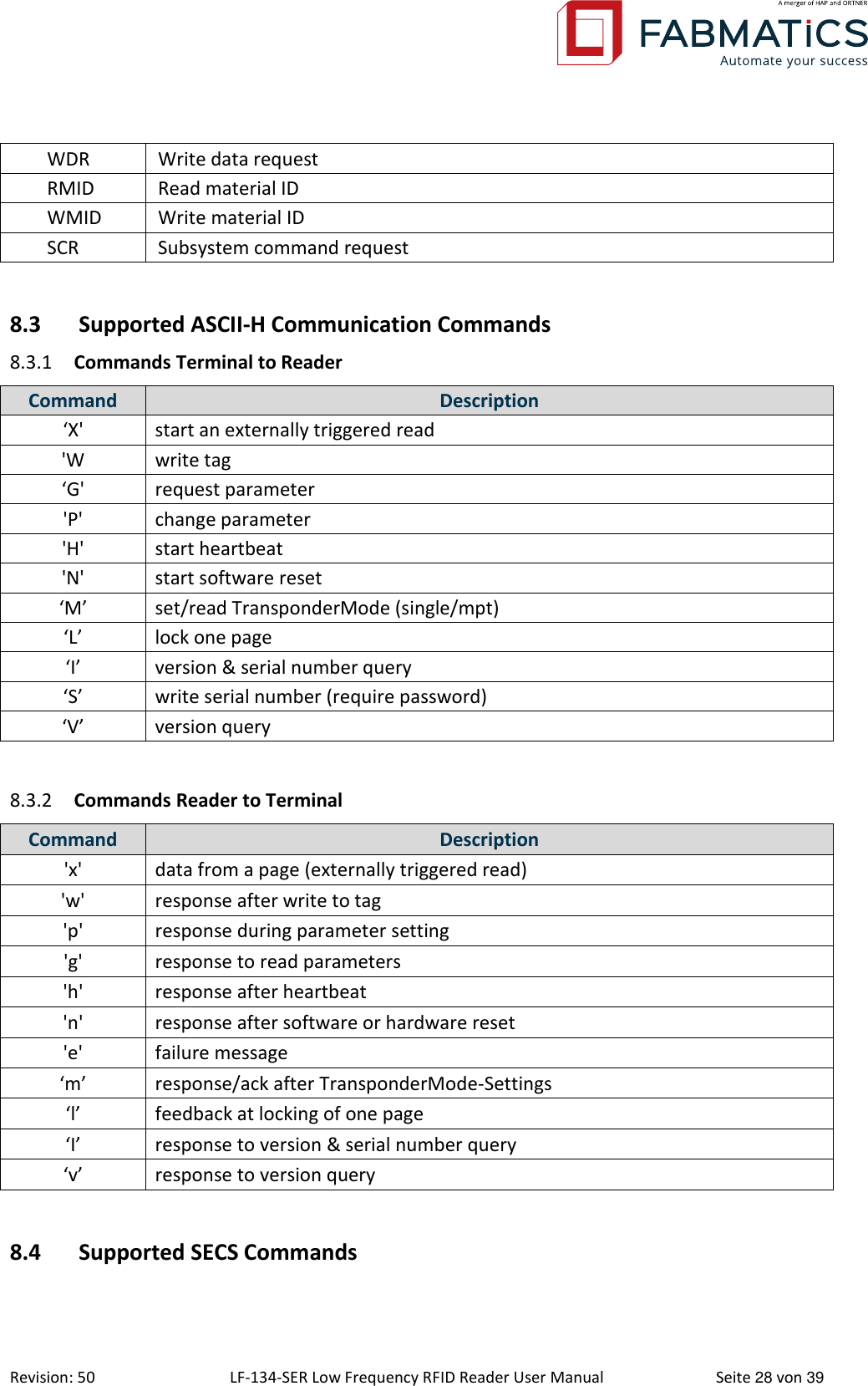
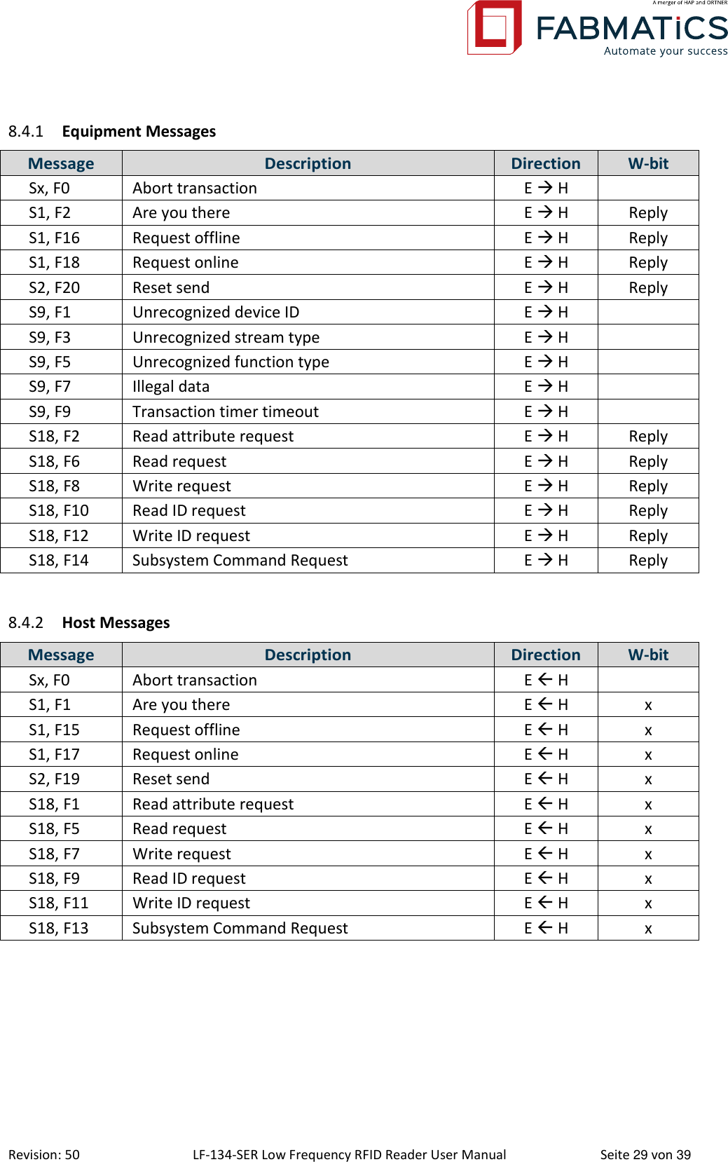
![Revision: 50 LF-134-SER Low Frequency RFID Reader User Manual Seite 30 von 39 9 Service Information 9.1 Contact To buy RFID components or spare parts, please contact our sales team: Phone: +49 351 65237-0 (only daytime CET) Fax: +49 351 65237-900 Mail: sales@fabmatics.com 9.2 Support For all purchased RFID components Fabmatics will provide free phone or email support. This includes support for the operation of the components and also support for the integra-tion/installation of components into other equipment. The phone support will be available at normal working times (8:00 a.m. to 5:00 p.m. CET, outside this timeframe a voice mail box will be available). To get support, please contact our team: Phone: +49 351 65237-0 (only daytime CET) Fax: +49 351 65237-900 Mail: support@fabmatics.com 9.3 Return Material Authorization (RMA) Before returning a defective device to Fabmatics, it is necessary to request a RMA number. This process ensures the proper return of the product and enables a faster classification and re-pair/replacement of the defective device. 1. Please contact us by phone or mail to get the RMA-Form and RMA-Number: Phone: +49 351 65237-00 (only daytime CET) Mail: support@fabmatics.com Fabmatics generates a RMA number Using the RMA number, the customer completes the RMA form 2. Ship the defective unit with the RMA-Report to: Fabmatics GmbH (vormals Roth & Rau - Ortner) R M A [ Number ] Zur Steinhöhe 1 011109 Dresden GERMANY](https://usermanual.wiki/Fabmatics/LF-134-SER-4/User-Guide-3311959-Page-30.png)