Fabmatics LF-134-SER-4 LF RFID device User Manual LF 134 SER Low Frequency RFID Reader
Fabmatics GmbH LF RFID device LF 134 SER Low Frequency RFID Reader
15_LF-134-SER UserMan
www.fabmatics.com
This document contains confidential information and has been provided by Fabmatics
GmbH for the purpose of evaluation. No part of this document may be copied, reproduced,
disclosed, or transferred by any means without prior written consent of Fabmatics GmbH.
Fabmatics GmbH reserves the right to make updates to the information in this document
without prior notice or approval from others. Please consult the author of this document to
ensure that you have the latest revision
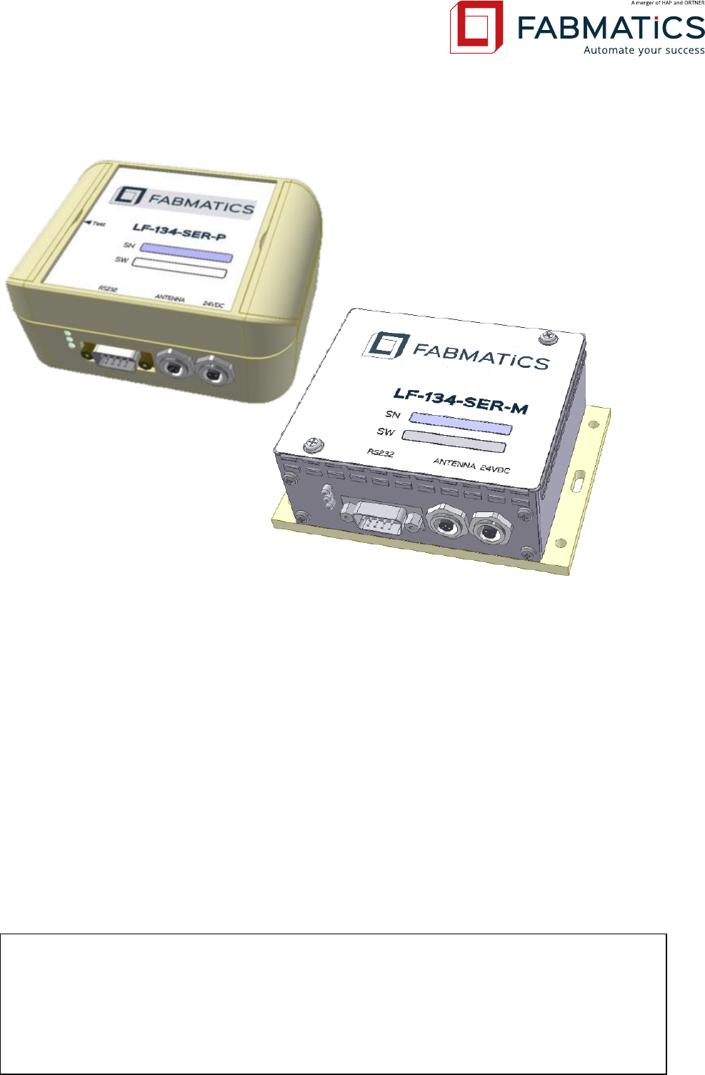
LF-134-SER
Low Frequency RFID Reader
User Manual
Revision: 50
Date: 03.02.2017

Revision: 50 LF-134-SER Low Frequency RFID Reader User Manual Seite 2 von 39
Revision History
#
Datum
Revision
Description
Name
33
05.10.2012
42
new layout, basic document update
CGU
34
16.10.2012
43
update technical data
CGU
35
06.10.2012
44
update antenna installation guide &
accessories / spare part list
CGU
36
06.01.2016
45
Update chapter 4 (FCC) and chapter
(product information label)
NEL
37
29.04.2016
46
Update chapter (NCC) and chapter (prod-
uct information label)
NEL
38
13.05.2016
47
Add chapters 5.2.1, 5.2.2 regarding NCC
label and update chapters 5.3 and 5.4 with
technical drawings with NCC labels
NEL
39
08.12.2016
48
Update for new HW Revision
SuK
40
03.02.2017
50
CE Declaration added
SuK

Revision: 50 LF-134-SER Low Frequency RFID Reader User Manual Seite 3 von 39
Content
1 Gerneral Informations ........................................................................................................ 5
2 Product Revisions ................................................................................................................ 6
3 Safety Instructions .............................................................................................................. 8
3.1 General .................................................................................................................... 8
3.2 Symbol and Tags ...................................................................................................... 9
3.3 ESD Instructions ..................................................................................................... 10
3.4 Proper Use ............................................................................................................. 10
3.5 Qualified Personnel ............................................................................................... 11
3.6 General Installation Notes ..................................................................................... 11
4 Application ........................................................................................................................ 13
5 Construction Design .......................................................................................................... 14
5.1 Design .................................................................................................................... 14
5.2 Product Information Label .................................................................................... 14
5.3 Drawing LF-134-SER-P-V4.0 ................................................................................... 15
5.4 Drawing LF-134-SER-M-V4.0 ................................................................................. 16
6 Hardware Design ............................................................................................................... 17
6.1 Technical Data ....................................................................................................... 17
6.2 Mainboard Layout ................................................................................................. 18
6.3 Antenna Power / Range Settings........................................................................... 18
6.4 Circuit Block Diagram ............................................................................................ 19
6.5 Serial Interface Specification ................................................................................. 19
6.6 Serial Interface Settings ......................................................................................... 20
6.7 Connector Pin Assignments ................................................................................... 21
7 Operation .......................................................................................................................... 23
7.1 Test Button ............................................................................................................ 23
7.2 LED Light-Status Desciption ................................................................................... 24
7.3 Reading and Writing Ranges ................................................................................. 24
7.4 Installation guide for RFID ferrite core antennas .................................................. 25
8 Communication Protocol Details ...................................................................................... 27
8.1 Supported ASCII-L Communication Commands .................................................... 27
8.2 Supported ASCII-A Communication Commands ................................................... 27
8.3 Supported ASCII-H Communication Commands ................................................... 28
8.4 Supported SECS Commands .................................................................................. 28

Revision: 50 LF-134-SER Low Frequency RFID Reader User Manual Seite 4 von 39
9 Service Information ........................................................................................................... 30
9.1 Contact .................................................................................................................. 30
9.2 Support .................................................................................................................. 30
9.3 Return Material Authorization (RMA) ................................................................... 30
9.4 Spare parts............................................................................................................. 31
9.5 Warranty ................................................................................................................ 31
9.6 Error Case .............................................................................................................. 31
9.7 Disposal ................................................................................................................. 31
9.8 Accessories ............................................................................................................ 32
10 Maintenance, repairs, troubleshoooting .......................................................................... 35
10.1 Maintenance.......................................................................................................... 35
10.2 Trouble Shooting ................................................................................................... 35
11 Attachment ....................................................................................................................... 36
11.1 Glossary ................................................................................................................. 36
11.2 EC-Declaration of Conformity ............................................................................... 37
11.3 USA Federal Communications Commission (FCC) ................................................. 38
11.4 Taiwanese National Communications Commission (NCC) Fehler! Textmarke nicht
definiert.
11.5 Related documents ............................................................................................... 39

Revision: 50 LF-134-SER Low Frequency RFID Reader User Manual Seite 5 von 39
1 General Information
This manual provides complete information about safety, operation and display elements, as
well as operation modes and technical data Serial RFID-Reader LF-134-SER.
Keep the manual in a handy place so it is accessible at any time for getting necessary infor-
mation.
Read the instructions carefully. The instructions must be understood and observed in all re-
spects by those persons, who are responsible for the installation, operation and maintenance of
this equipment.
Revision: 50 LF-134-SER Low Frequency RFID Reader User Manual Seite 6 von 39
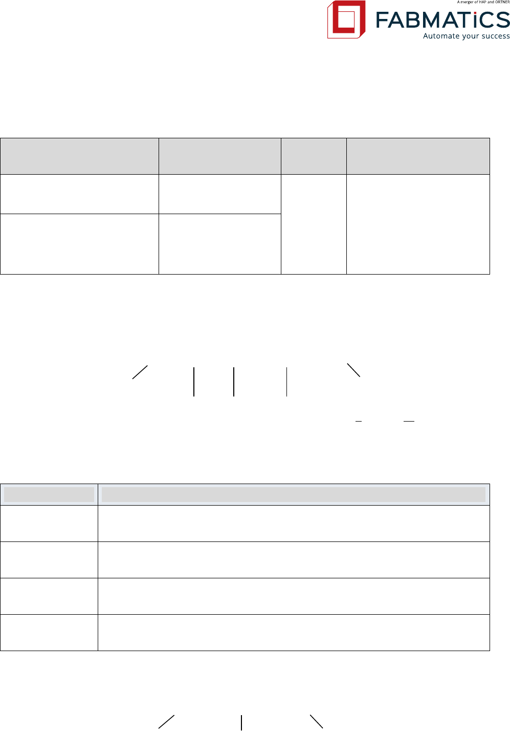
2 Product Revisions
Product Code
Product Revision
Hardware
Version
Available Communication
Protocols
LF-134-SER-M-V4.0
4.0
(without Test button)
3.0
- ASCII-L (Fabmatics
Light)
- ASCII-H (Hermos)
- ASCII-A (Asyst)
- SECS (SEMI E99)
LF-134-SER-P-V4.0
4.0
(with Test button)
The product code consists of following information:
LF – 134 – SER – P – V4.0
Frequency Range Product Revision
Frequency Interface Case Version (Plastic or Metal)
Available software versions are:
Version
Description
ASCII-L-V3.0.0
Fabmatics developed short command set.
Test button implemented, sending error messages to host.
ASCII-H-V2.0.0
Command set compatible to Hermos protocol.
Test button not implemented.
ASCII-A-V2.0.0
Command set compatible to Asyst ASCII CIDRW Version S protocol.
Test button implemented without sending any messages to host.
SECS-V2.0.0
SECS communication by SEMI E99.
Test button not implemented.
The software code consists of following information:
ASCII – L – V2.6.1
Communication Type Protocol Type Software Version

Revision: 50 LF-134-SER Low Frequency RFID Reader User Manual Seite 7 von 39
NOTE: Product revisions are identified by revision numbers. Each revision number corre-
sponds to versions of three components of the product: hardware, software and
manual. Each product revision number is distinctive. The product revision number is
assigned accordingly to distinctive versions of the three components. Version altera-
tion of one of the components (hardware, software, manual) may alter accordingly
the product revision number.

Revision: 50 LF-134-SER Low Frequency RFID Reader User Manual Seite 8 von 39
3 Safety Instructions
Please recognize the safety regulations. Nevertheless, there are dangers associated with the
use of the equipment even for its intended purpose. Therefore you should read the following
safety information carefully and keep it in mind. Install and operate this equipment only if it is
in perfect condition and with reference to this manual. Do not use the equipment if it is dam-
aged!
3.1 General
Read and understand all safety and operating instructions before installing and operating the
device.
This instruction is designed for specially trained personnel. This device is NOT intended for use
by the “general population” in an uncontrolled environment. Installation, operation and error
handling the device shall be carried out by specially trained personnel only.
Keep these instructions. Store this manual in a place that can be accessed at any time by all
persons involved in installing, operating and error handling the device.
Heed all warnings. Follow all warnings on and inside the device and operating instructions.
Install in accordance with the manufacturer's instructions only.
Only use attachments, accessories and connecting cables supplied by the manufacturer.
All error handling except the error handling listed in this manual must be carried out by the
manufacturer.
People with hearing aids should remember that radio signals transmitted by the device might
cause a very unpleasant buzzing noise in their hearing aids.
Do not connect the device to any kind of power supply such as a standard household power
supply. The device should be connected to a power supply of the type described in these in-
structions only.
When you disconnect a cable, pull on its conductor and not on the cable itself. Keep the con-
nector evenly aligned to avoid bending any connector pins. When you connect a cable, ensure
that the connector pins are positioned correctly.
Never over bend the antenna cable or expose it to mechanical loads.
When replacement parts are required, use the replacement parts specified by the manufactur-
er only. Unauthorized substitutions may result in fire, electric shock, or other hazards.
Revision: 50 LF-134-SER Low Frequency RFID Reader User Manual Seite 9 von 39
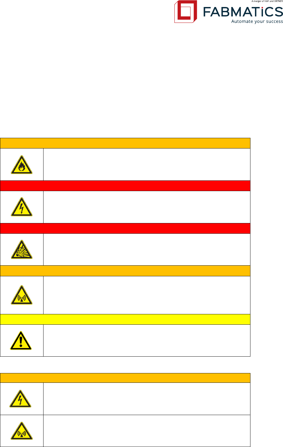
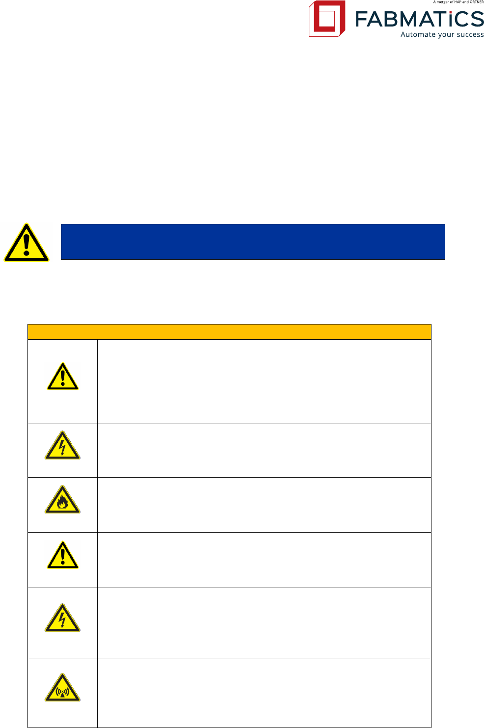
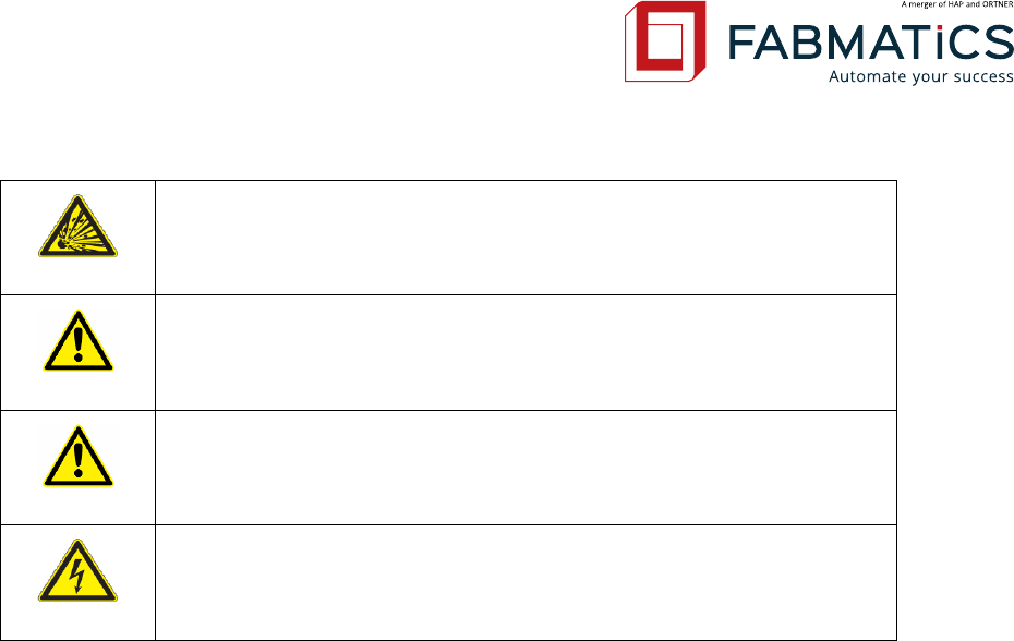
3.2 Symbol and Tags
Special tags are used in this document to alert technicians to personal and equipment safety
hazards. Before using this document, a thorough understanding of specific safety issues de-
tailed in the Manual must be understood. The following types of safety tags appear in this doc-
ument. Note that the following are only examples; they do not indicate a specific hazard associ-
ated with the product.
WARNING!
Flammable Material
Flames – Risk of fire
DANGER!
Electricity; Electrical Hazard
Lightning bolt – Dangerous voltage
DANGER!
Explosive Material; Explosion Hazard
Object exploding – Risk of explosion
WARNING!
Non-Ionizing Radiation; Radio Frequency
Abstract radiation transmitter – indicates electromagnetic radia-
tion
CAUTION!
General Warning
Important instructions
All antenna resonant circuit components carry high voltage!
The installer is responsible for installing the device to comply with
FCC requirements of human exposure to radio frequency.
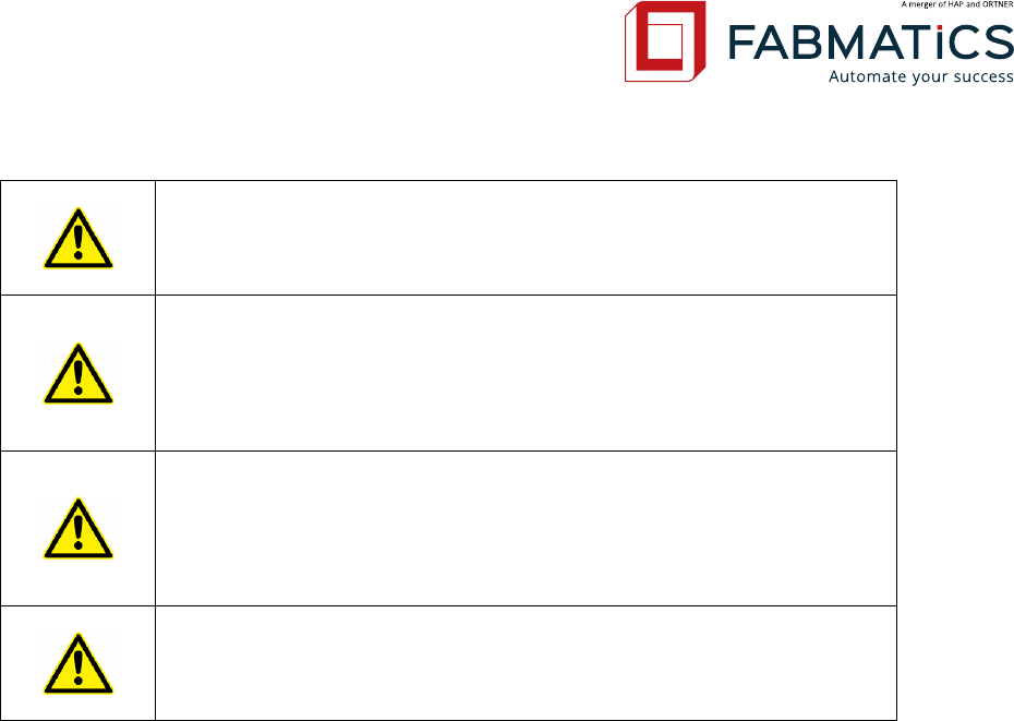
Revision: 50 LF-134-SER Low Frequency RFID Reader User Manual Seite 10 von 39
To prevent fire, shock hazard, or annoying interference, use rec-
ommended accessories only.
When removing the housing lid, note that the housing lid is con-
nected to the case with a cable. Remove the lid carefully to prevent
damage – do not pull it! Do not operate the device when the hous-
ing lid is removed!
Do NOT operate this device without a proper antenna attached.
Proper antennas are antennas supplied by the manufacturer and
listed in section
„Antennas“.
Never locate the antenna so that it is very close to or touching
parts of the body while transmitting.
3.3 ESD Instructions
Static electricity can harm electronic components inside the device. All persons who install or
maintain the device must be trained in ESD protection. ESD protection measures must be ob-
served when opening the device.
Before removing or inserting components, disconnect the power supply.
To prevent electrostatic damage, static electricity must be discharged from the body and tools
before touching components inside the device.
Touch electro sensitive components carefully at their edges only.
3.4 Proper Use
This product was developed for reading and writing the TIRIS® transponder only. Any other use
of this device would constitute abuse. All antenna resonant circuit components carry high volt-
age! To prevent fire, shock hazard, or annoying interference, use recommended accessories
only. Do not operate the device when the housing is removed! Proper antennas are antennas
supplied by the manufacturer“. Never locate the antenna so that it is very close to or touching
parts of the body while transmitting. This product is designed to be mounted and operated in
an industrial environment as a built-in-device only. It is not designed to be used as a stand-
alone or a portable device in a non-industrial environment, such as a household, automotive or
open-air environment.
Revision: 50 LF-134-SER Low Frequency RFID Reader User Manual Seite 11 von 39
3.5 Qualified Personnel
This manual is designed for specially trained personnel only. This device must be installed and
maintained by the manufacturer or its specially trained representatives. Intervention or error
handling not expressively approved in this manual must be carried out by the manufacturer’s
personnel only. If you are unsure about the qualifications that are actually required, contact the
manufacturer.
3.6 General Installation Notes
This device is designed for use in an indoor industrial environment
only. Installation is only permitted in an environmental indoor cli-
mate with a constant temperature of between 0°C and +50°C /
32°F and 122°F, humidity between 25% and 80%, and a maximum
temperature of +50°C / 122°F.
Do not install or use this device in or near water. Never spill liquids
of any kind onto the device. Should spillage occur, unplug the de-
vice and let it check from a technician.
Do not install near heat sources such as radiators, heat registers,
stoves, or other apparatus (including amplifiers) that produce heat.
Do not install the device in a flammable environment.
Never expose the device to intense changes in temperature, oth-
erwise condensation can develop inside the device and cause dam-
ages.
Do not locate the device near overhead power lines or other elec-
tric lights, or power circuits or where it can encounter such circuits.
When installing the device, take extreme care not to encounter
such circuits as they can cause serious injury or death.
The device should not be used in the immediate vicinity of electri-
cal units (such as medical units, monitors, telephones, televisions
and energy-saver lamps), magnetic data carriers, or metallic ob-
jects. This could result in reduced reading/writing ranges.
Unqualified interventions may result in personal injury
or damage to the device!
Revision: 50 LF-134-SER Low Frequency RFID Reader User Manual Seite 12 von 39
Never use the device in potentially explosive areas (such as paint
shops).
Do not position the device in a location where it can suffer from
vibration or shock.
When the device is installed, the installation location must be ade-
quately illuminated.
Do not install the device during periods of lightning.
Revision: 50 LF-134-SER Low Frequency RFID Reader User Manual Seite 13 von 39
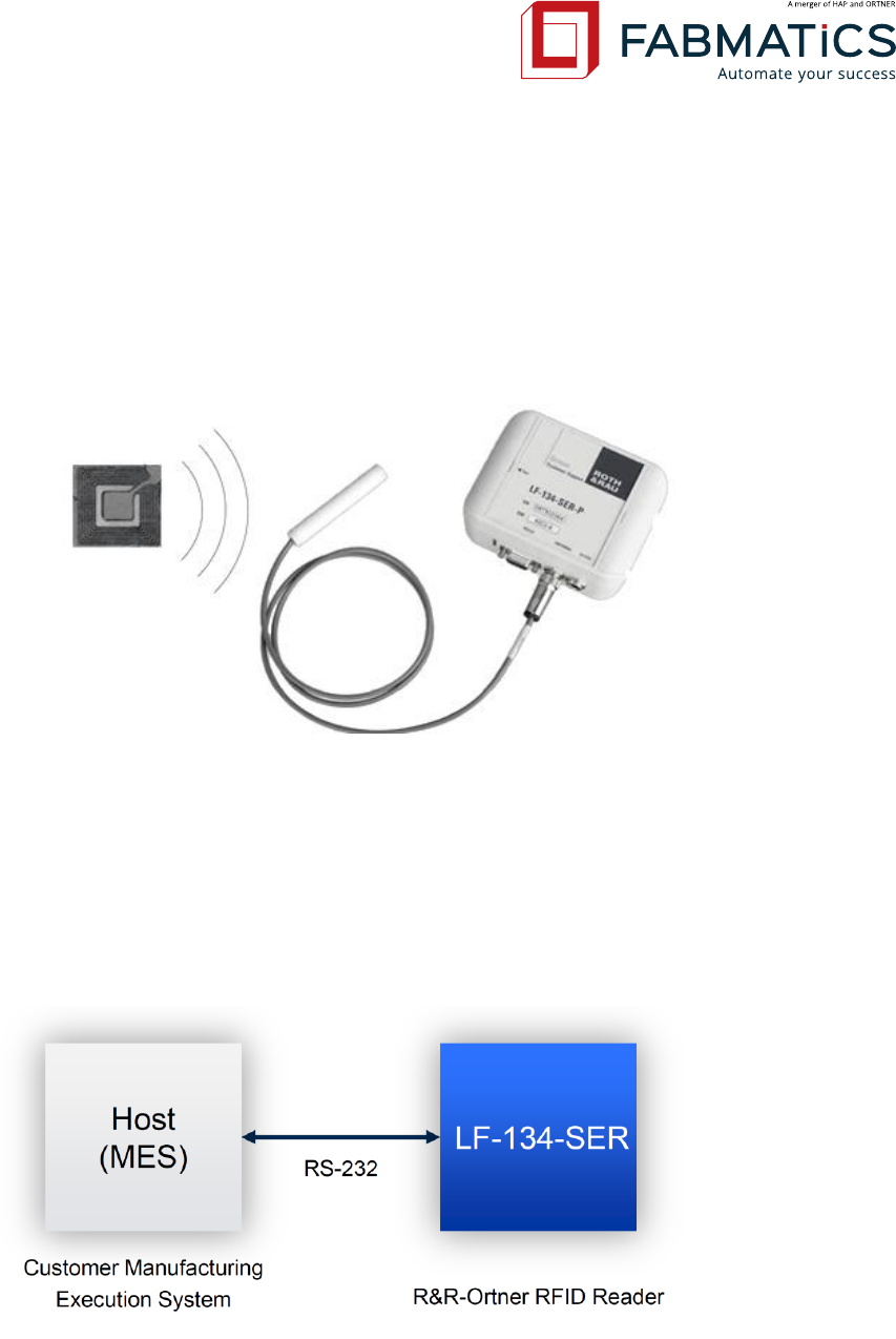
4 Application
RFID provides simple and fast radio identification via a short range.
The Low frequency reader LF-134-SER is a 134.2 kHz Low-frequency RFID solution. It is special-
ized for applications in production and logistics. It is less sensitive to interference than HF solu-
tions and designed for rugged applications.
Ideal application environments are production facilities featuring only one or very few identifi-
cation goods (i.e. Load port). The module supports 134.2 kHz half duplex transponders, reading
of “Read-only” as well as “Read-Write” transponder types.
Host communication is realized by a Serial RS-232 interface with data rates up to 57.600 Kbit/s.
Supported communication protocols to a superordinate host system are:
- ASCII-L (Fabmatics ASCII light protocol)
- ASCII-H (Hermos compatible)
- ASCII-A (Asyst CIDRW compatible)
- SECS (SEMI E99 compatible)
Revision: 50 LF-134-SER Low Frequency RFID Reader User Manual Seite 14 von 39
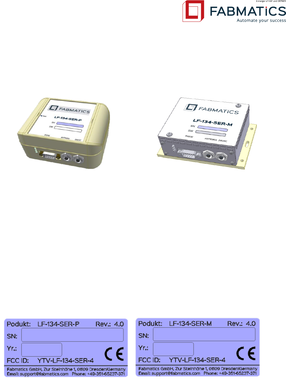
5 Construction Design
5.1 Design
The LF-134-SER ID-Reader is available in two case versions:
Plastic Case
contains vapour metallized shielding inside
Metal Case
usage of thin plate metal for efficient shielding
5.2 Product Information Label
The product information label contains the product name (Model), product revision, serial
number and year of production. The dimension of label is 21,5mm x 46 mm. Furthermore the
FCC number YTV-LF-134-SER-4 is listed and the CE-mark.
For the location of product information label for LF-134-SER-P-V4.0 please see engineer draw-
ing in chapter 5.3
For the location of product information label for LF-134-SER-M-V4.0 please see engineer draw-
ing in chapter 5.4
The serial label is seen in the following figures.
Revision: 50 LF-134-SER Low Frequency RFID Reader User Manual Seite 15 von 39
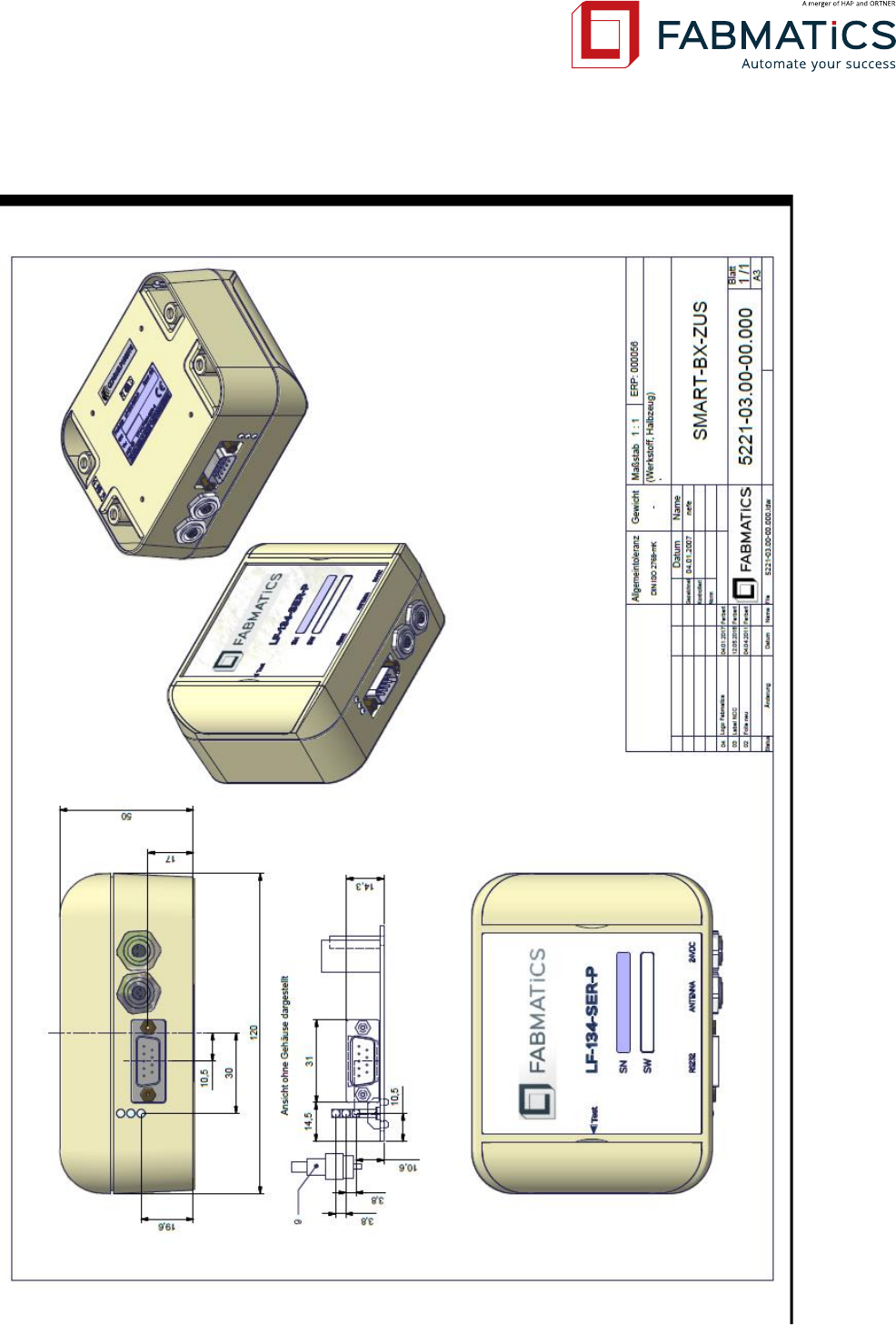
5.3 Drawing LF-134-SER-P-V4.0
Revision: 50 LF-134-SER Low Frequency RFID Reader User Manual Seite 16 von 39
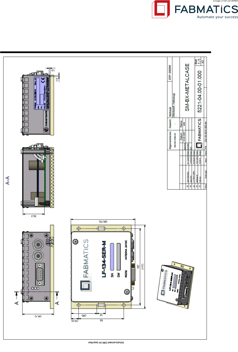
5.4 Drawing LF-134-SER-M-V4.0

Revision: 50 LF-134-SER Low Frequency RFID Reader User Manual Seite 17 von 39
6 Hardware Design
6.1 Technical Data
Version
LF-134-SER-P (Plastic)
LF-134-SER-M (Metal)
Application
Suitable for environments with
low electromagnetic interference.
Particularly suitable for production
environments with high
electromagnetic interference.
Dimensions (w-h-d)
120 x 50 x 90mm
117 x 44 x 90mm
97 x 39 x 90mm (w/o Base plate)
Weight
235g
255g
Case Material
ABS
Case: tinplate
Base plate: POM
Voltage supply
24 V/DC ±3%
Plug Power Supply 000278 or parent System Power Supply1
Fuse
Use of Plug Power Supply 105124: integrated
Use of parent System Power Supply: 0,5A slow-blow2
Power consumption
Idle mode: 0,6W (25mA)
Read mode: 3,2W (132mA)
Antenna specification
Designed for use with 48µH ±3% and 110µH ±3%, Ferrite or Air-coil
Antenna
(available in different versions)
RFID Frequency
134.2kHz
RFID Chip Type
TIRIS compatible chip 134.2kHz HDX/FSK
Supported
Transponder Types
HDX/FSK, MPT, SAMPT, RW, RO (e.g. RI-TRP-DR2B)
Max. reading range
For specific information, please refer to the respective antenna
data sheets.
Reading time one page
110msec Average
Permanent reading
maximum 1 cycle/s
Connectors
- 24 V/DC Power (Binder plug socket, Series 712-2p)
- Antenna (Binder plug socket, Series 712-3p)
- Serial RS-232 (DSUB-9 female)
MCBF | MTBF
≥ 1,000,000 reading cycles | ≥ 40,000h
Operating temperature
0°C to +50°C (duty cycle: <50%)
Storage temperature
-25°C to +50°C
1
Specification for external low power source (LPS) has to match according section 2.5 of EN 60950-1:2006 standard.
2
Make sure that the LF-134-SER Reader is supplied from a separately fused busbar!
Revision: 50 LF-134-SER Low Frequency RFID Reader User Manual Seite 18 von 39
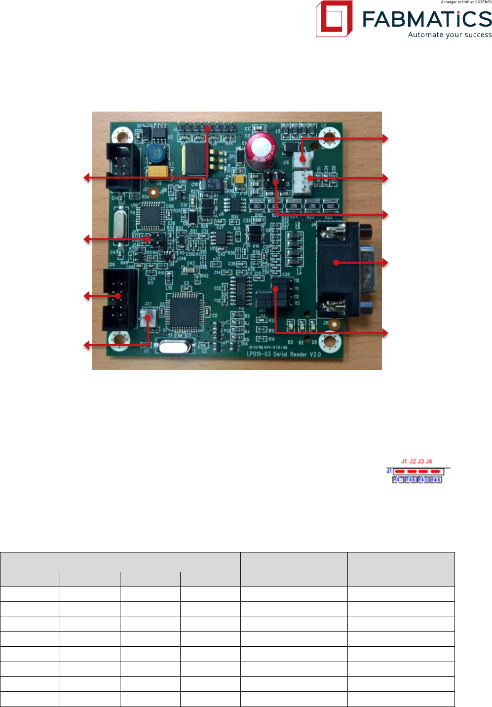
6.2 Mainboard Layout
6.3 Antenna Power / Range Settings
Jumper-Block J1 can be used to decrease the RF output power level for the
transmitting amplifier, which will result in a decreased reading range also.
This can be necessary if several Antennas needs to placed very closely to each
other or if an high read frequency up to 14 cycles/s needs to perform.
All values are calculated values and might be differ a bit.
Jumper Block J1
RF supply Voltage
(approx.)
Read distance
(approx.)
J1.1
J1.2
J1.3
J1.4
-
-
-
-
23,75 V
100%
-
-
-
On
14,75 V
85%
On
-
-
-
12,50 V
81%
On
-
-
On
9,70 V
74%
On
On
-
-
8,75 V
71%
On
On
-
On
7,40 V
67%
On
On
On
-
6,87 V
66%
On
On
On
On
6,07 V
63%
Antenna
Output Power
Jumper-Block
J1
ISP Connector
J26
RS-232 Setting
Jumper-Block
J10-J15
SUB-D9
RS-232
Connector
J4
Antenna
Connector J3
Power
Connector J16
Testbutton
Connector
J22
Antenna In-
ductance
J28/J27/J2
Receiver
Sensitivity
J23/J24
Revision: 50 LF-134-SER Low Frequency RFID Reader User Manual Seite 19 von 39
NOTE: With full output power (no jumper) it is not recommended to read faster than ones per
second! For perform hing speed cycles up to 14 times per second permanently, the output
power must reduced to 85% by setting jumper J1.4 (obove R44).
By default no jumper is set (100% output power).
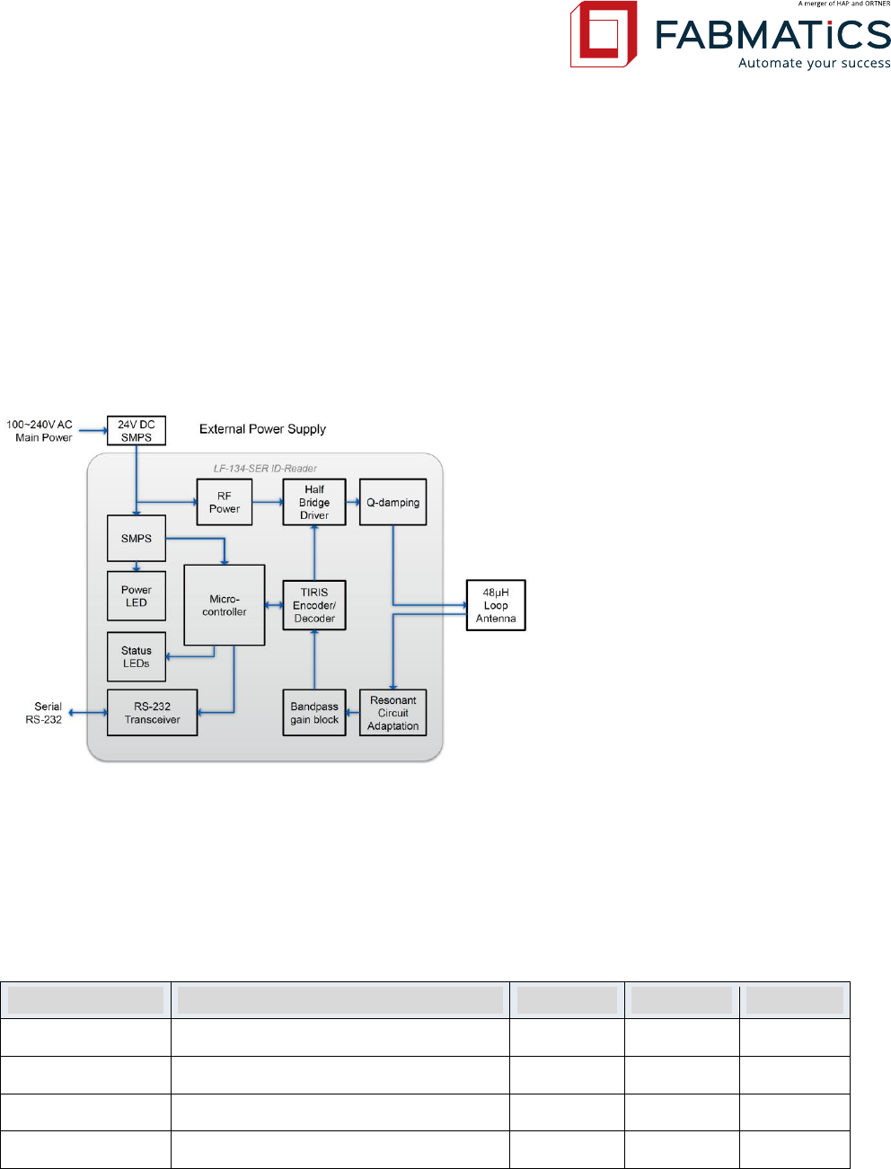
6.4 Circuit Block Diagram
6.5 Serial Interface Specification
The setting of the serial interface depends on the applied software protocol.
Protocol
Bit rate (bit/sec)
Data bits
Stop bits
Parity
ASCII-L
9600
8
1
none
ASCII-H
4800, 9600, 19200, 28800, 57600
8
1
even
ASCII-A
4800, 9600, 19200, 28800, 57600
8
1
none
SECS
9600
8
1
none
Revision: 50 LF-134-SER Low Frequency RFID Reader User Manual Seite 20 von 39
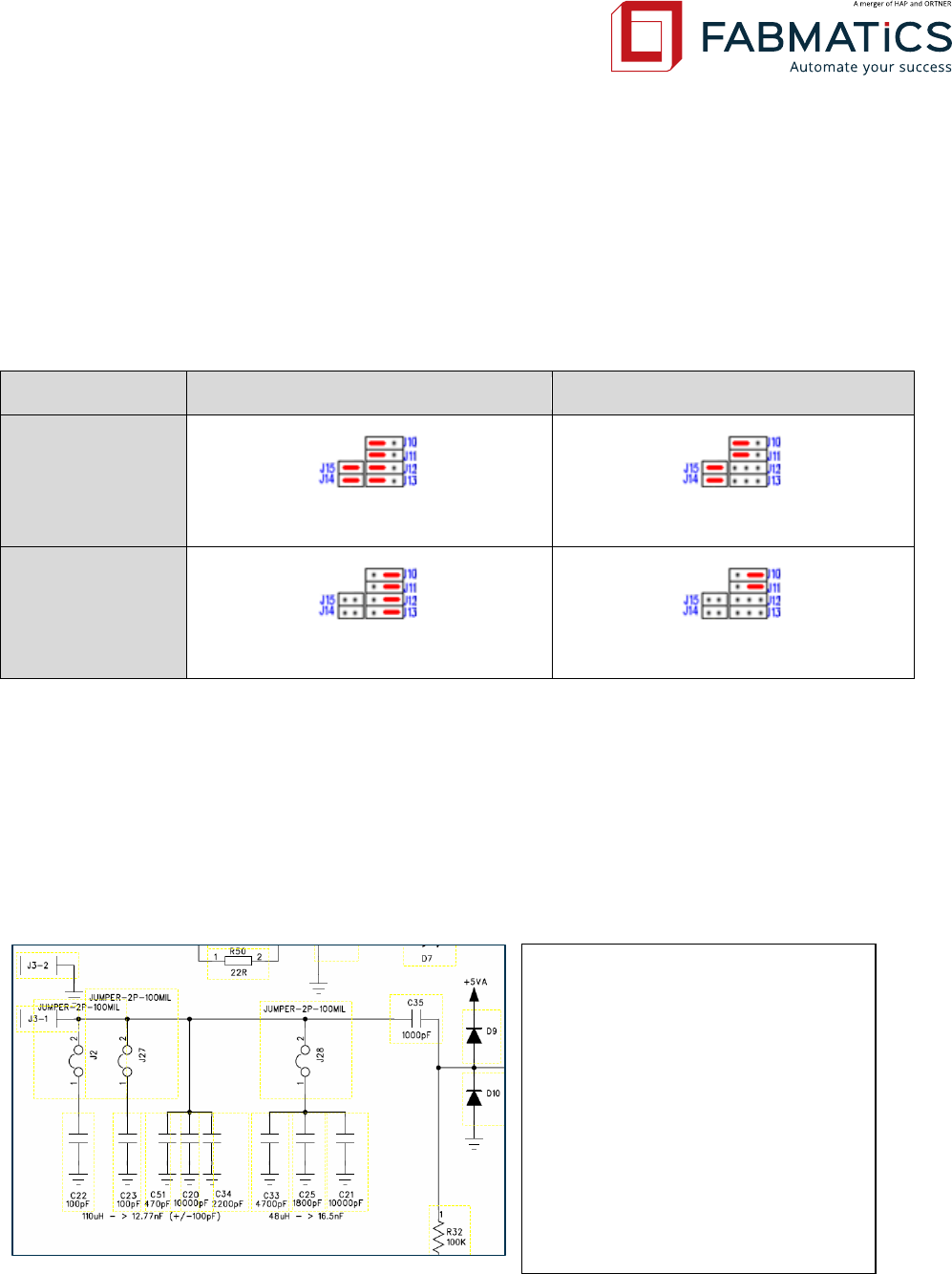
6.6 Serial Interface Settings
The Serial RS-232 communication interface supports different operation modes. To change
these modes, the jumper J10 – J15 need to be modified as shown below.
The default mode is Standard RS-232 with Handshake.
RS-232 Mode
Handshake On
Handshake Off
Standard
J10 - J15 (default)
J10 | J11 | J14 | J15
TTL Level
J10 – J13
J10 | J11
6.7 Antenna Inductance Settings
It is possible to connect antennas with different inductance values to the reader. Therefore it is
necessary to adjust the resonant circuit.
For possible setting see the following picture.
Jumper setting for J27 /J28 and J2
6.8 Receiver Sensitivity Settings
110µH setting J28 = open
J27 = closed
J2 = open.
111 µH setting J28 = open
J27 = open
J2 = open
109 µH setting J28 = open
J27 = closed
J2 = closed
48 µH setting J28 = closed
J27 = closed
J2 = closed
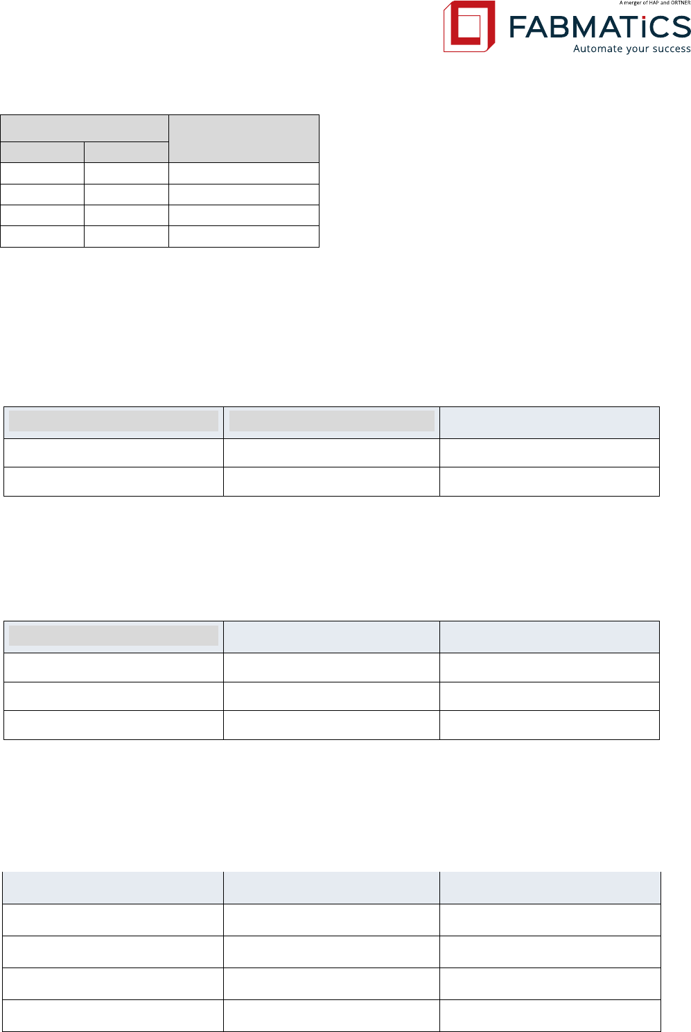
Revision: 50 LF-134-SER Low Frequency RFID Reader User Manual Seite 21 von 39
Jumper Block J23/24
Sensitivity
J23
J24
-
-
40dB gain => 100x
On
-
29dB gain => 30x
-
On
29dB gain => 30x
On
On
23dB gain => 15x
6.9 Connector Pin Assignments
6.9.1 Power Connector
In table below the Electrical specification is given for connector J16.
Pin
Name
Description
1
Vcc
24 V/DC ±3%
2
GND
Ground
6.9.2 Antenna Connector
In table below the Electrical specification is given for connector J3.
Pin
Name
Description
1
RF -
Antenna (-)
2
GND
Ground (used for wire shield)
3
RF+
Antenna (+)
6.9.3 Serial Interface
The Serial Host-Interface J4 uses the RS-232 standard with female DSUB-9 connector.
Pin
Name
Description
1 | 4 | 6 | 9
-
not connected
2
RxD
Receive Data
3
TxD
Transmit Data
5 | 10 | 11
GND
Ground

Revision: 50 LF-134-SER Low Frequency RFID Reader User Manual Seite 22 von 39
7
RTS
Request to Send
8
CTS
Clear to Send
Revision: 50 LF-134-SER Low Frequency RFID Reader User Manual Seite 23 von 39
7 Operation
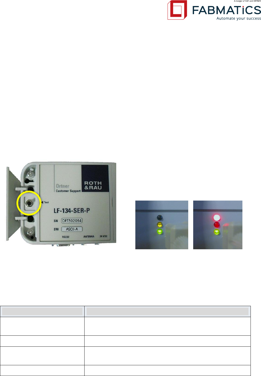
7.1 Test Button
The plastic version LF-134-SER-P is equiped with a Read Test Button for perform quick Antenna
alignment, range or transponder tests manually.
The button starts a single page read (page 0, same as command ’R’) with an interval of approx-
imately 250msec as long as the button is pressed. Depending on protocol version, the read re-
sult is send to the serial interface and shown by the Status LEDs.
ID read OK
ID read Fail
The functioning of the Test-Button depends on protocol version:
Protocol Version
Test button function
ASCII-L
Trigger ID read, status is indicating by device LEDs.
Data and failure messages will be send to host!
ASCII-H
not implemented
ASCII-A
Trigger local ID read, status is indicating by device LEDs.
No messages will be send to host.
SECS
not implemented
Revision: 50 LF-134-SER Low Frequency RFID Reader User Manual Seite 24 von 39
7.2 LED Light-Status Description
In the table below the meaning of all signal LEDs is described.
Status LEDs
Desciption
Green active
Power OK / Idle mode
Yellow active
Reading in progress (Read success in test mode)
Red active
Reading error
7.3 Reading and Writing Ranges
The provided reading ranges shown here and in their respective Antenna datasheets are measured with
best conditions. In real environment the ranges can be differ due to disturbing material like metal or any
kind of electro-magnetically fields near to the Antenna location. Please thorough improve the conditions
before make final decisions about the Antenna location.
Writing ranges in general are approximately 60% of the reading ranges.
Be aware that tag reading and writing very close to the antenna will not be possible. As a guide value
keep the distance above 10mm !
For detailed information about individual range characteristics of available Antenna-Types
please refer to the corresponding data sheets like ANT-04-35E / ANT-08-65E / ANT-10-100E.
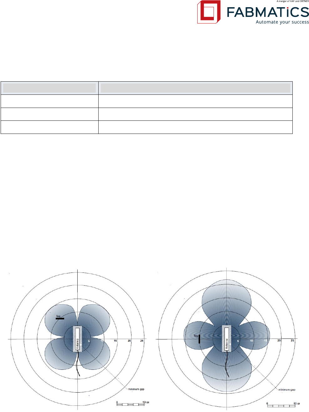
Example range measures with Antenna ANT-08-65E:
Antenna aligned orthogonal to the ID Tag,
reading rage up to 150mm
Antenna aligned parallel to the ID Tag,
reading range up to 220mm
Revision: 50 LF-134-SER Low Frequency RFID Reader User Manual Seite 25 von 39
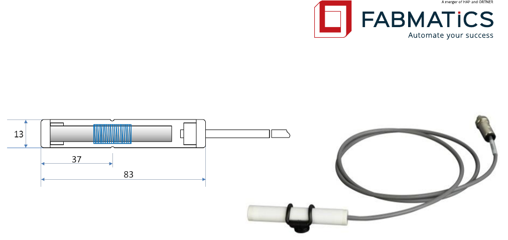
Technical Antenna data of ANT-08-65E:
Operating Frequency: 134.2 KHz
Inductance: 48 µH ±3%
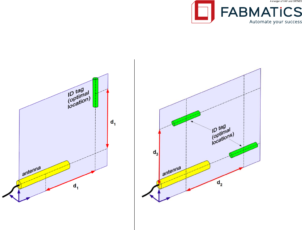
7.4 Installation guide for RFID ferrite core antennas
This guide shall show you the best way to install RFID antennas to your devices to achieve safe reading
results. It considers two possible orientations between antenna and ID tag:
1. Antenna is aligned orthogonal to the ID tag, in one layer
2. Antenna is aligned parallel to the ID tag, in one layer
General information:
- Don’t attach RFID antennas directly to metal surfaces and avoid ferromagnetic materials! Leave
a gap of at least 5mm and use plastic mountings and screws for fixing the antenna.
- Don’t install antennas, cables or reading devices close to electromagnetic radiating devices such
as switched-mode power supplies!
- Only use shielded cables and try not to loop the remains!
- Try to align antenna and ID tag in one layer. (see case explanations)
- Maximum distances are given for best surrounding conditions. In reality the maximum dis-
tances may be lower due to other electromagnetic interferences! So, try to keep the distance
between antenna and ID tag as low as possible.
Revision: 50 LF-134-SER Low Frequency RFID Reader User Manual Seite 26 von 39
Case 1: Antenna orthogonal to ID tag
Case 2: Antenna parallel to ID tag
Antenna type ANT08-65E
Antenna type ANT08-65E
d1 min = 10 mm
d1 max = 120 mm
d2 min = 10 mm
d3 min = 10 mm
d2 max = 200 mm
d3 max = 140 mm
Considering the suggested alignment between antenna and ID tag should perform best results.
If you still encounter problems or for further information please contact our Customer Support.
Revision: 50 LF-134-SER Low Frequency RFID Reader User Manual Seite 27 von 39
8 Communication Protocol Details
The implementation of all available protocol versions is based on the ASCII communication protocol for
RFID Reader – Type TIRIS® by Texas Instruments.
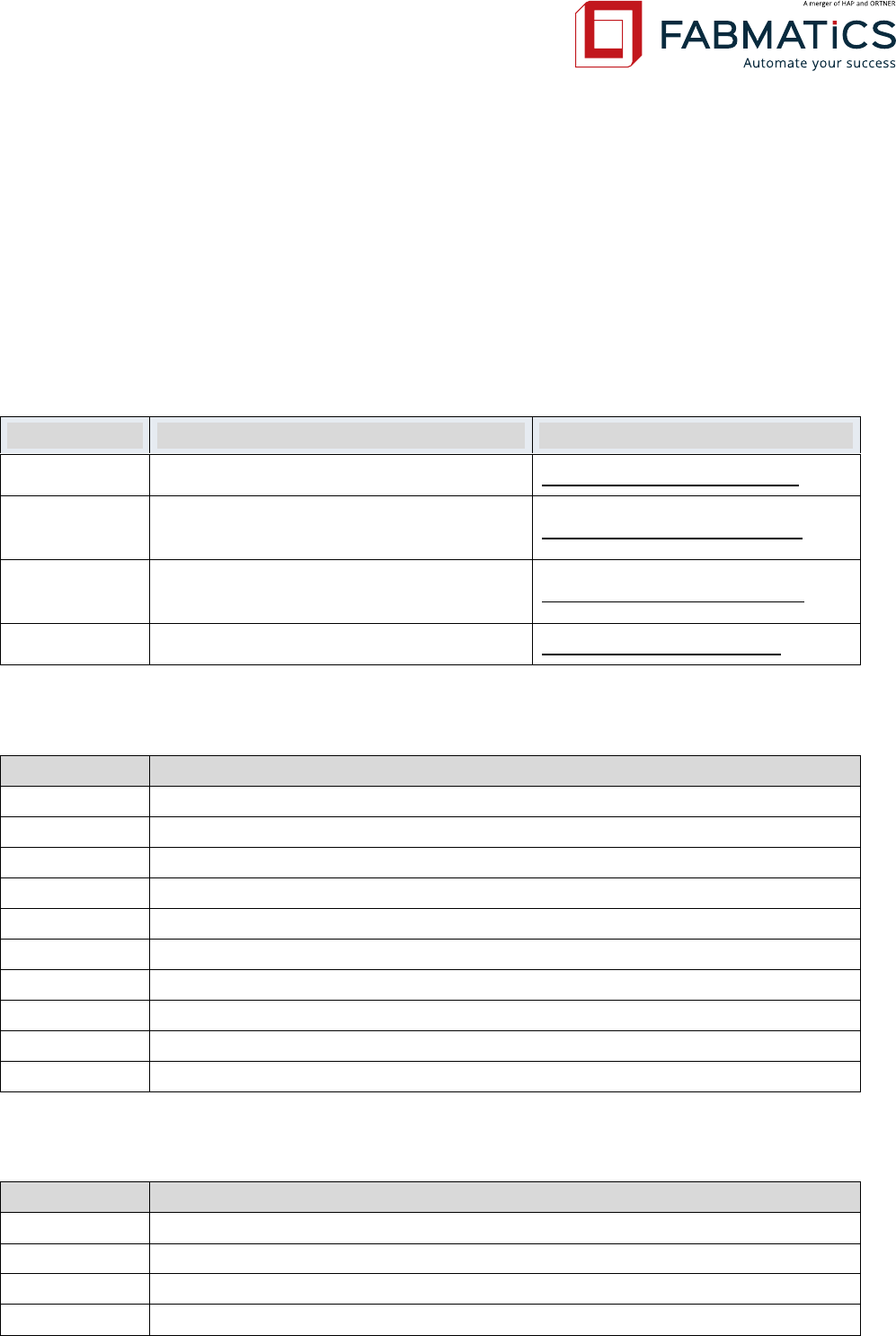
NOTE: For detailed descriptions of each Communication Protocol, please refer to the re-
spective Software-Manuals listed below.
Protocol
Description
User Manual
ASCII-L
Fabmatics developed short command set
UME_LF-134-SER_SW-ASCII-L
ASCII-A
Command set compatible to Asyst ASCII
CIDRW Version S protocol
UME_LF-134-SER_SW-ASCII-A
ASCII-H
Command set compatible to Hermos
protocol
UME_LF-134-SER_SW-ASCII-H
SECS
SECS communication by SEMI E99
UME_LF-134-SER_SW-SECS
8.1 Supported ASCII-L Communication Commands
Command
Description
R
Read RO, RW and MPT(Only page 0) transponders
W
Write RW transponders
V
Version and Serial number
M
Read MPT and SAMPT (Only page 0) transponders
U
Write MPT transponders
N
Read SAMPT transponders
I
Write SAMPT transponders
L
Lock MPT transponders
K
Lock SAMPT transponders
E
Returns details for last Error
8.2 Supported ASCII-A Communication Commands
Command
Description
R
Are you there
RAR
Read attribute request
WAR
Write attribute request
RR
Read request
Revision: 50 LF-134-SER Low Frequency RFID Reader User Manual Seite 28 von 39
WDR
Write data request
RMID
Read material ID
WMID
Write material ID
SCR
Subsystem command request
8.3 Supported ASCII-H Communication Commands
8.3.1 Commands Terminal to Reader
Command
Description
‘X'
start an externally triggered read
'W
write tag
‘G'
request parameter
'P'
change parameter
'H'
start heartbeat
'N'
start software reset
‘M’
set/read TransponderMode (single/mpt)
‘L’
lock one page
‘I’
version & serial number query
‘S’
write serial number (require password)
‘V’
version query
8.3.2 Commands Reader to Terminal
Command
Description
'x'
data from a page (externally triggered read)
'w'
response after write to tag
'p'
response during parameter setting
'g'
response to read parameters
'h'
response after heartbeat
'n'
response after software or hardware reset
'e'
failure message
‘m’
response/ack after TransponderMode-Settings
‘l’
feedback at locking of one page
‘I’
response to version & serial number query
‘v’
response to version query
8.4 Supported SECS Commands
Revision: 50 LF-134-SER Low Frequency RFID Reader User Manual Seite 29 von 39
8.4.1 Equipment Messages
Message
Description
Direction
W-bit
Sx, F0
Abort transaction
E H
S1, F2
Are you there
E H
Reply
S1, F16
Request offline
E H
Reply
S1, F18
Request online
E H
Reply
S2, F20
Reset send
E H
Reply
S9, F1
Unrecognized device ID
E H
S9, F3
Unrecognized stream type
E H
S9, F5
Unrecognized function type
E H
S9, F7
Illegal data
E H
S9, F9
Transaction timer timeout
E H
S18, F2
Read attribute request
E H
Reply
S18, F6
Read request
E H
Reply
S18, F8
Write request
E H
Reply
S18, F10
Read ID request
E H
Reply
S18, F12
Write ID request
E H
Reply
S18, F14
Subsystem Command Request
E H
Reply
8.4.2 Host Messages
Message
Description
Direction
W-bit
Sx, F0
Abort transaction
E H
S1, F1
Are you there
E H
x
S1, F15
Request offline
E H
x
S1, F17
Request online
E H
x
S2, F19
Reset send
E H
x
S18, F1
Read attribute request
E H
x
S18, F5
Read request
E H
x
S18, F7
Write request
E H
x
S18, F9
Read ID request
E H
x
S18, F11
Write ID request
E H
x
S18, F13
Subsystem Command Request
E H
x

Revision: 50 LF-134-SER Low Frequency RFID Reader User Manual Seite 30 von 39
9 Service Information
9.1 Contact
To buy RFID components or spare parts, please contact our sales team:
Phone: +49 351 65237-0 (only daytime CET)
Fax: +49 351 65237-900
Mail: sales@fabmatics.com
9.2 Support
For all purchased RFID components Fabmatics will provide free phone or email support. This
includes support for the operation of the components and also support for the integra-
tion/installation of components into other equipment. The phone support will be available at
normal working times (8:00 a.m. to 5:00 p.m. CET, outside this timeframe a voice mail box will
be available).
To get support, please contact our team:
Phone: +49 351 65237-0 (only daytime CET)
Fax: +49 351 65237-900
Mail: support@fabmatics.com
9.3 Return Material Authorization (RMA)
Before returning a defective device to Fabmatics, it is necessary to request a RMA number. This
process ensures the proper return of the product and enables a faster classification and re-
pair/replacement of the defective device.
1. Please contact us by phone or mail to get the RMA-Form and RMA-Number:
Phone: +49 351 65237-00 (only daytime CET)
Mail: support@fabmatics.com
Fabmatics generates a RMA number
Using the RMA number, the customer completes the RMA form
2. Ship the defective unit with the RMA-Report to:
Fabmatics GmbH
(vormals Roth & Rau - Ortner)
R M A [ Number ]
Zur Steinhöhe 1
011109 Dresden
GERMANY

Revision: 50 LF-134-SER Low Frequency RFID Reader User Manual Seite 31 von 39
IMPORTANT! Please prominently display the RMA number on the packaging, to al-
low us to serve you faster.
Acknowledgment of receipt and processing of the RMA request by Fabmatics
3. Returning the repaired/replaced device
9.4 Spare parts
The components in our current array of products are available as spare parts to our customers.
In case of spare part requests for products which are already removed from our actual array of
products, Fabmatics GmbH requires the type information. All components have an expected
product lifetime of 10 years. For this time period we are able to provide spare parts.
9.5 Warranty
The warranty period is 24 months and begins with the moment of delivery of the device as
proved by an invoice or other documents. The warranty includes the repair of all damages to
the device that occurs within the warranty period and which is evidently caused by faults of the
material or production defects.
The warranty does not include damages caused by incorrect connection, inappropriate handling
and non-observance of the technical reports.
9.6 Error Case
In case of serious system disorders please contact the Fabmatics Support:
Phone: +49 351 65237-0
Fax: +49 351 65237-900
Email: support@fabamtics.com
9.7 Disposal
Within the European Union Fabmatics will take back any delivered equipment for disposal. For
further information on the return, please contact the Fabmatics Support.
For disposal the equipment by your own, make sure to observe all applicable laws.
Revision: 50 LF-134-SER Low Frequency RFID Reader User Manual Seite 32 von 39
9.8 Accessories
Component
Description
Order Codes
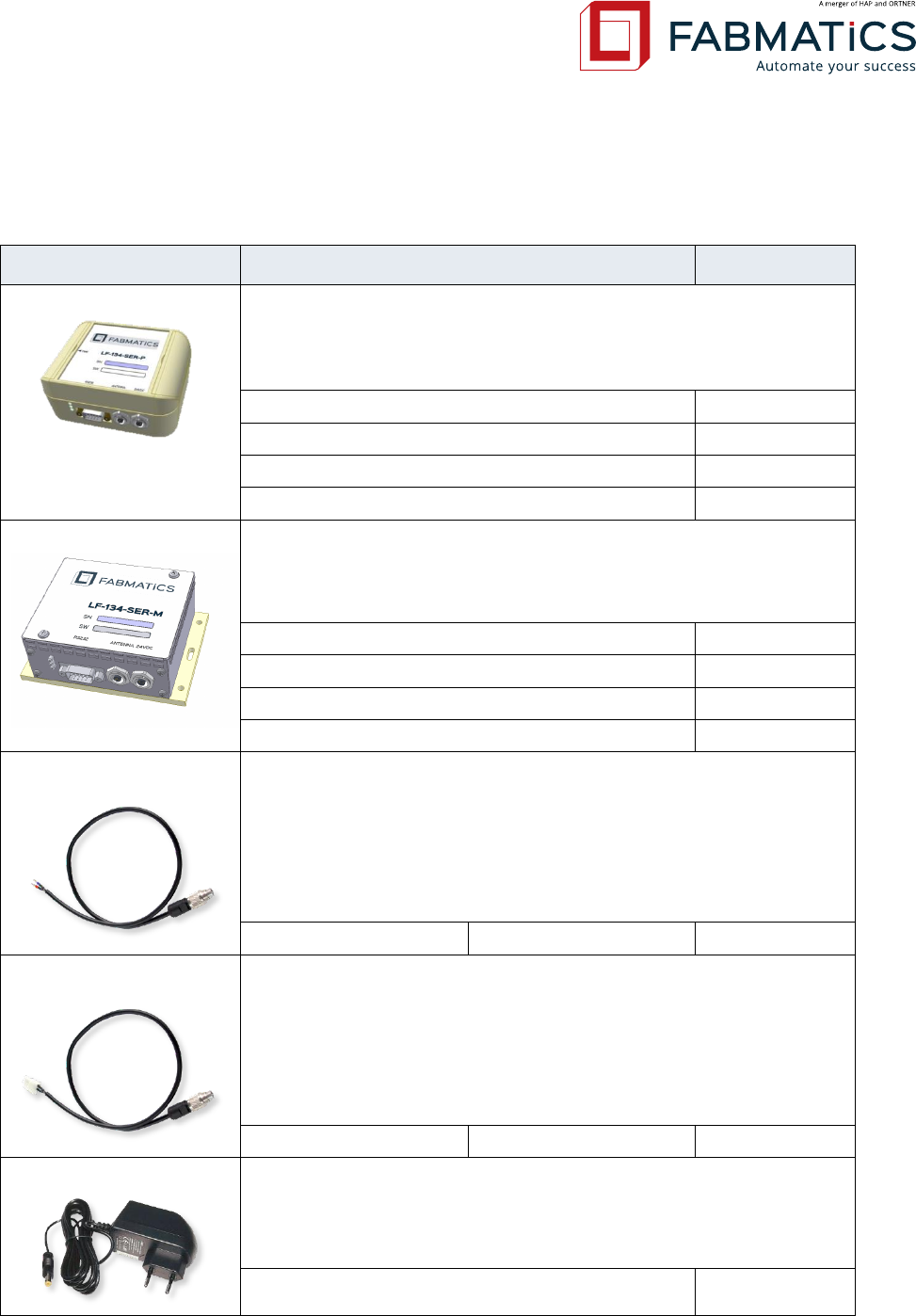
LF-134-CAN-P
134.2 KHz low frequency RFID-reader with serial RS-232 host
interface. Available with different Communication Protocols.
Case material: plastic (ABS)
LF-134-SER-P-4.0 ASCII-A (Asyst)
105125
LF-134-SER-P-4.0 ASCII-L (Fabmatics ASCII light)
105126
LF-134-SER-P-4.0 ASCII-H (Hermos)
105127
LF-134-SER-P-4.0 SECS (SEMI E99)
105128
LF-134-CAN-M
134.2 KHz low frequency RFID-reader with serial RS-232 host
interface. Available with different Communication Protocols.
Case material: tinplate metal
LF-134-SER-M-4.0 ASCII-A (Asyst)
105129
LF-134-SER-M-4.0 ASCII-L (Fabmatics ASCII light)
105130
LF-134-SER-M-4.0 ASCII-H (Hermos)
105131
LF-134-SER-M-4.0 SECS (SEMI E99)
105132
OEM-POW-OPEN
Power cable for all versions of LF-134-SER LF-ID-readers and
CAN2Web Advanced MINI gateway devices.
Open ends for clamp or screw mounting and Binder connector
712–2p.
OEM-POW-OPEN-(X)
cable length max. 2m
105122
OEM-POW-M
Power cable for all versions of LF-134-SER LF-ID-readers and
CAN2Web Advanced MINI gateway devices.
Molex connector 5557-02R and Binder connector 712–2p.
OEM-POW-M-500
cable length 0.5m
105123
Plug Power Supply
Wide range plug power supply 100-240 V/AC, 50/60 Hz.
Output 24 V/DC, 24 W (1A), with Binder connector 712–2p.
cable length 1.5m
105124
Revision: 50 LF-134-SER Low Frequency RFID Reader User Manual Seite 33 von 39
Fabmatics Test Suite
Comprehensive software tool for testing all Fabmatics
CAN/Serial LF and HF ID-readers in conjunction with a CAN2Web
gateway.
For further information please contact our support:
support@fabmatics.com
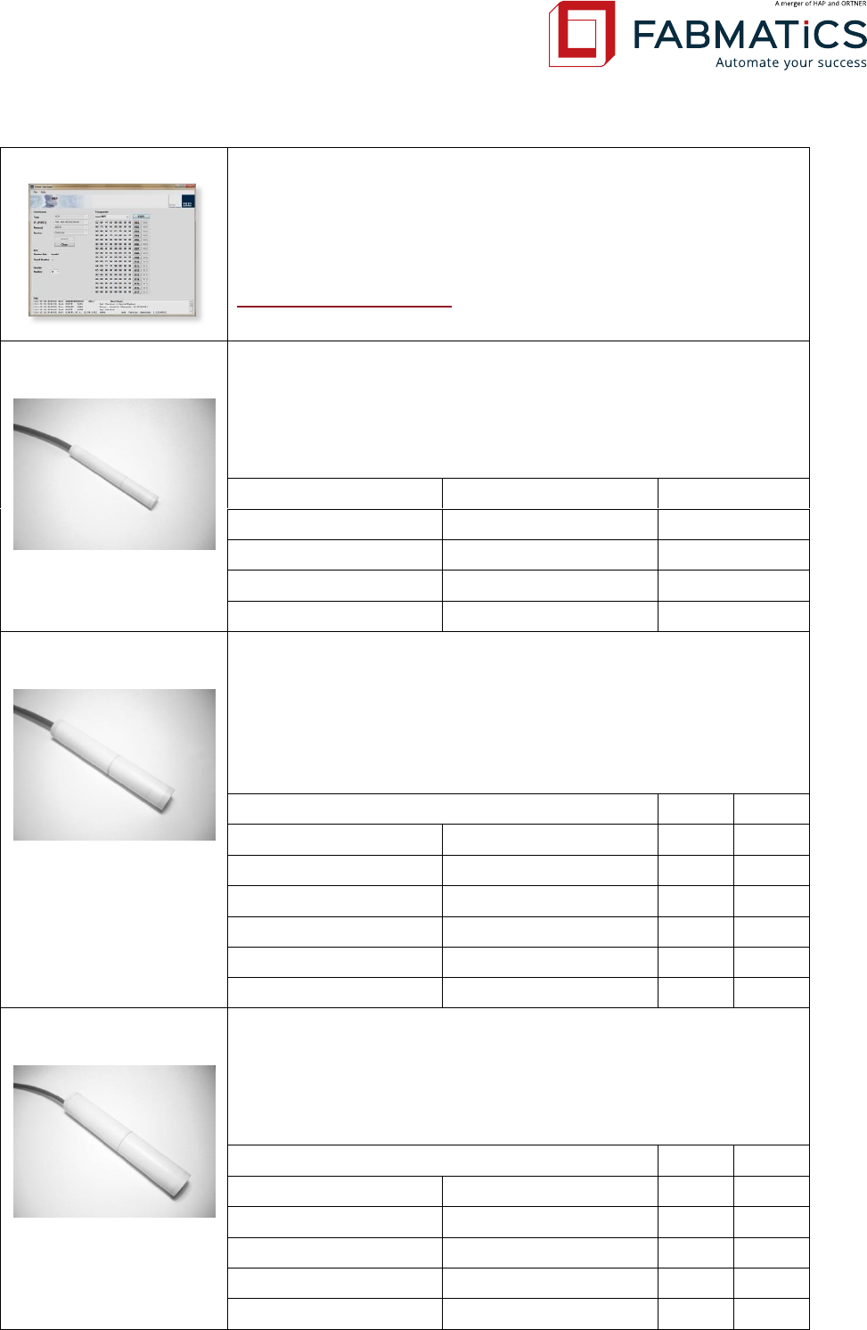
ANT-04-35EM B
External LF Ferrite Antenna
core dimensions (diameter, length): 4 × 35 mm
inductance: 47 μH
connector type: Binder 712-3p
available cable lengths: up to 2m
ANT-04-35EM B-500
cable length 0.5m
105133
ANT-04-35EM B-8000
cable length 0.8m
105134
ANT-04-35EM B-1000
cable length 1.0m
105135
ANT-04-35EM B-1500
cable length 1.5m
105136
ANT-04-35EM B-2000
cable length 2.0m
105137
ANT-08-65EM B
External LF Ferrite Antenna
core dimensions (diameter, length): 8 × 65 mm
inductance: 47 μH
connector type: Binder 712-3p
available cable lengths: up to 2m
available with high flex cable
normal
high flex
ANT-08-65EM B/BF-500
cable length 0.5m
105138
105148
ANT-08-65EM B/BF-800
cable length 0.8m
105139
105149
ANT-08-65EM B/BF-1000
cable length 1.0m
105140
105150
ANT-08-65EM B/BF-1300
cable length 1.3m
105141
-
ANT-08-65EM B/BF-1500
cable length 1.5m
105153
105154
ANT-08-65EM B/BF-2000
cable length 2.0m
105142
105155
ANT-10-100EM B
External LF Ferrite Antenna
core dimensions (diameter, length): 10 × 100 mm
inductance: 47 μH
connector type: Binder 712-3p
available cable lengths: up to 2m
normal
high flex
ANT-10-100EM B/BF-500
cable length 0.5m
105143
105156
ANT-10-100EM B/BF-800
cable length 0.8m
105144
105157
ANT-10-100EM B/BF-1000
cable length 1.0 m
105145
105158
ANT-10-100EM B/BF-1500
cable length 1.5m
105146
105151
ANT-10-100EM B/BF-2000
cable length 2.0m
105147
105152
Revision: 50 LF-134-SER Low Frequency RFID Reader User Manual Seite 34 von 39
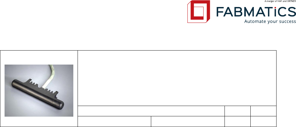
ANT-10-100E B
External LF Ferrite Antenna
core dimensions (diameter, length): 10 × 100 mm
inductance: 47 μH
connector type: Binder 712-3p
available cable lengths: up to 2m
available with high flex cable
normal
high flex
ANT-10-100E B/BF 800
cable length 0.8m
-
105159

Revision: 50 LF-134-SER Low Frequency RFID Reader User Manual Seite 35 von 39
10 Maintenance, repairs, troubleshooting
10.1 Maintenance
Cleaning of the surfaces is possible with Isopropanol (IPA).
The plant operator is responsible for the maintenance.
Before start working on the system, always check for mechanical damage and pay attention to
any unusual noises!
10.2 Trouble Shooting
In case of any problems check the following list point to point.
1. Power LED is off?
> check power supply (try to replace it) or power cable
In case of frequent read fails, try to use the Read Test Button (only LF-134-SER-P >V3.1) or use
the Fabmatics Test Suit (OTS) Software. If the red LED is flashing equably fast during read
operation, the reader indicates a persistent Read-Error. Proceed with step 2.
2. RFID Tag is out of range?
> decrease distance between Antenna and Tag and check Transponder- (Tag)
alignment - recheck read operation
3. RFID Tag is damaged?
> replace Tag and recheck read operation
4. Antenna, Antenna-cable or Antenna-plug is damaged?
> replace Antenna and recheck read operation
5. Power supply has malfunction (under voltage)?
> replace power supply and recheck read operation
6. Reader Hardware is damaged?
> replace the ID-Reader and recheck read operation

Revision: 50 LF-134-SER Low Frequency RFID Reader User Manual Seite 36 von 39
11 Attachment
11.1 Glossary
ASCII
American Standard Code of Information Inter-exchange
CAN
Controller Area Network
RF
Radio Frequency
RFID
Radio Frequency IDentification
LF / HF
Low / High Frequency
HDX
Half DupleX
ISP
In-Circuit Programmer
FSK
Frequency Shift Keying
MPT / SPT
Multi / Single Page Transponder
RO / RW
Read Only / Read and Write
SAMPT
Selective Addressable Multi Page Transponder
ABS
Acrylonitrile Butadiene Styrene (plastic material)
POM
Polyoxymethylen (plastic material)
SMPS
Switched Mode Power Supply
MES
Manufacturing Execution System
SEMI
Semiconductor Equipment and Materials International
SECS
SEMI Equipment Communication Standard
MTBF
Mean Time Between Failures
MCBF
Mean Cycles Between Failures
TIRIS
Texas Instruments Registration and Identification System (RFID Standard)
Revision: 50 LF-134-SER Low Frequency RFID Reader User Manual Seite 37 von 39
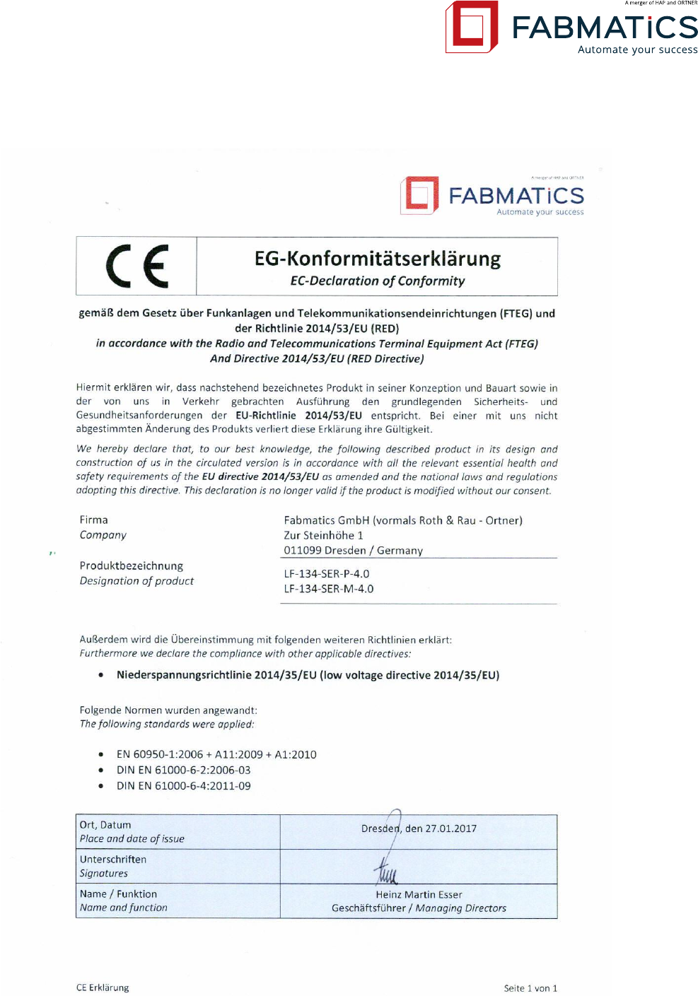
11.2 EC-Declaration of Conformity

Revision: 50 LF-134-SER Low Frequency RFID Reader User Manual Seite 38 von 39
11.3 USA Federal Communications Commission (FCC)
LF-134-SER is a Part 15 Low Power Communication Device Transmitter (DXX) and a Part 15 Class
B Computing Device Peripheral (JBP). It is a device that is marketed for use in industrial or busi-
ness environment, exclusive of a device which is marketed for use by the general public or is
intended to be used in the home.
11.3.1 Compliance
The product complies with FCC Subpart C – Intentional Radiators § 15.207 and § 15.209 and the
product complies with Subpart B – Unintentional Radiators § 15.107 and § 15.109, when used
for its intended purpose. This equipment generates, uses, and can radiate radio frequency en-
ergy and, if not installed and used in accordance with the instruction manual, may cause harm-
ful interference to radio communications. Operation of this equipment in a residential area is
likely to cause harmful interference in which case the user will be required to correct the inter-
ference at his/her own expense.
11.3.2 Antenna Requirements
The antenna is removable and does not employ a unique connector; however, the device is
professionally installed and maintained. Therefore, the described reader LF-134-SER complies
with FCC Subpart C – Intentional Radiators § 15.203.
11.3.3 Labeling Requirements
The described reader LF-134-SER is not large enough to accommodate a label with the standard
FCC compliance statement. It is therefore provided here as follows:
This device complies with Part 15 of the FCC Rules. Operation is subject to the following two
conditions: (1) this device may not cause harmful interference, and (2) this device must accept
any interference received, including interference that may cause undesired.
For further labelling information please see chapter 0.

Revision: 50 LF-134-SER Low Frequency RFID Reader User Manual Seite 39 von 39
© Fabmatics GmbH
(vormals Roth & Rau - Ortner)
Zur Steinhöhe 1
01109 Dresden / Germany
Tel. +49 351 65237 0
Fax +49 351 65237 900
info@fabmatics.com
www.fabmatics.com
11.4 Related documents
UMA_LF-134-SER_SW-SECS_Eng_Rev02
UMA_LF-134-SER_SW-ASCII-L_Eng_Rev01
UMA_LF-134-SER_SW-ASCII-H_Eng_Rev01
UMA_LF-134-SER_SW-ASCII-A_Eng_Rev01
DAS_ANT-08-65EM_Eng_Rev05
DAS_ANT-04-35EM_Eng_Rev03
DAS_ANT-10-100EM_Eng_Rev05
The documents apply in their respective current version.