Factorytech S1 Function Phone User Manual Turbo Mobile
Factorytech S.A. Function Phone Turbo Mobile
Contents
- 1. User manual
- 2. User Manual
User manual

Maintenance Manual
1
S
Se
er
rv
vi
ic
ce
e
M
Ma
an
nu
ua
al
l

Maintenance Manual
2
Contents
1.1 6004 ................................................................................................................................................. 3
1.2 Basic Feature .................................................................................................................................. 3
1.3 Typical Application ......................................................................................................................... 4
2 Main board explored overview ........................................................................................................ 5
3.Detailed Function Circuit ............................................................................................................... 6
3.1 Download Module .......................................................................................................................... 6
3.2 Audio Module .................................................................................................................................. 6
3.2.1 Micphone Circuit ......................................................................................................................... 6
3.2.2 Receiver Circuit ........................................................................................................................... 7
3.2.3 Speaker Circuit ............................................................................................................................ 7
3.3 FM Module ...................................................................................................................................... 8
3.4 BT Module ....................................................................................................................................... 8
3.5 RF Module ....................................................................................................................................... 9
3.6 LCM Module .................................................................................................................................. 10
3.7 CAMERA MODULE ..................................................................................................................... 10
3.8 KEYPAD interface ........................................................................................................................ 11
4.1 RF Part .......................................................................................................................................... 11
4.2 BB Part .......................................................................................................................................... 11
Maintenance Manual
3
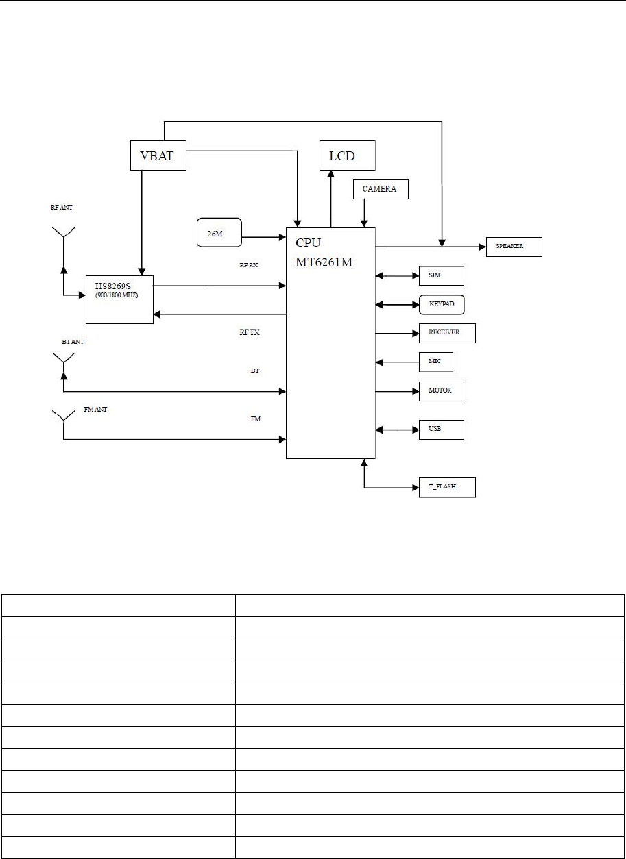
1 6004 Module Features
1.1 6004
Figure 1.1: 6004 Module
1.2 Basic Feature
Table 1-1: Feature
Platform
MTK6261(M/D)
Band
GSM850/900,/DCS1800/PCS1900
LCM
CAMERA
30w
MCP Module
Internal Nor Flash
BT Module
Internal BT Module
FM RX Module
Internal FM Module
Audio PA
Internal Audio (CLASS A\B)
SIM
Dual SIM
I/O
Micro USB 5PIN
Torch
Support
Keypad
23 Key
Maintenance Manual
4
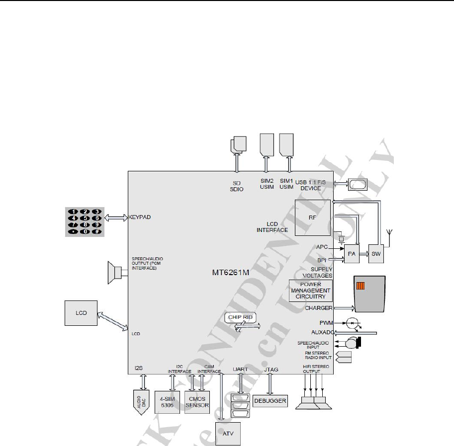
1.3 Typical Application
Figure 1.2: Typical Application with MTK6261 Based platform
Maintenance Manual
5
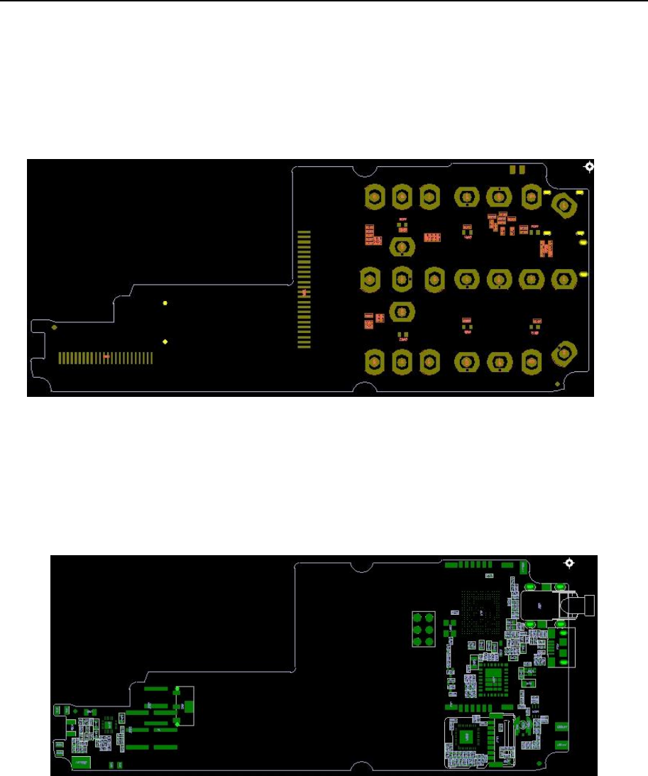
2 Main board explored overview
Figure 2.1: top
Figure 2.2: bottom
Maintenance Manual
6
3.Detailed Function Circuit
3.1 Download Module
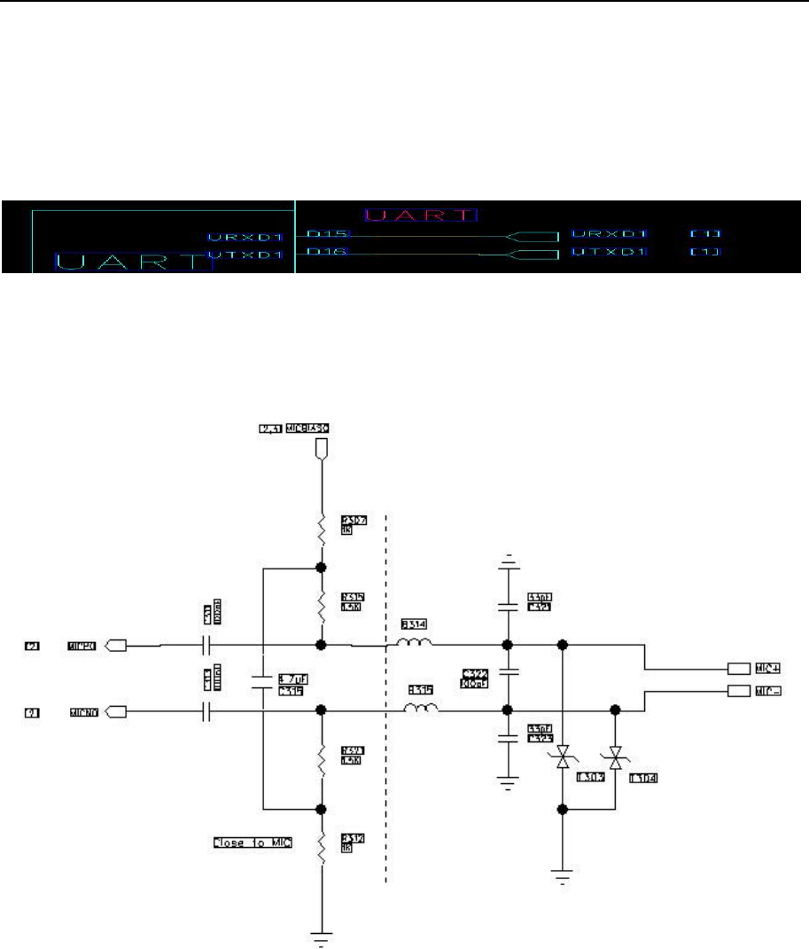
Download through USB port, program select download mode, when connect UTXD1(pin
D15 U0RTS) to GND.
Figure 3.1: TP107 D/L Interface
3.2 Audio Module
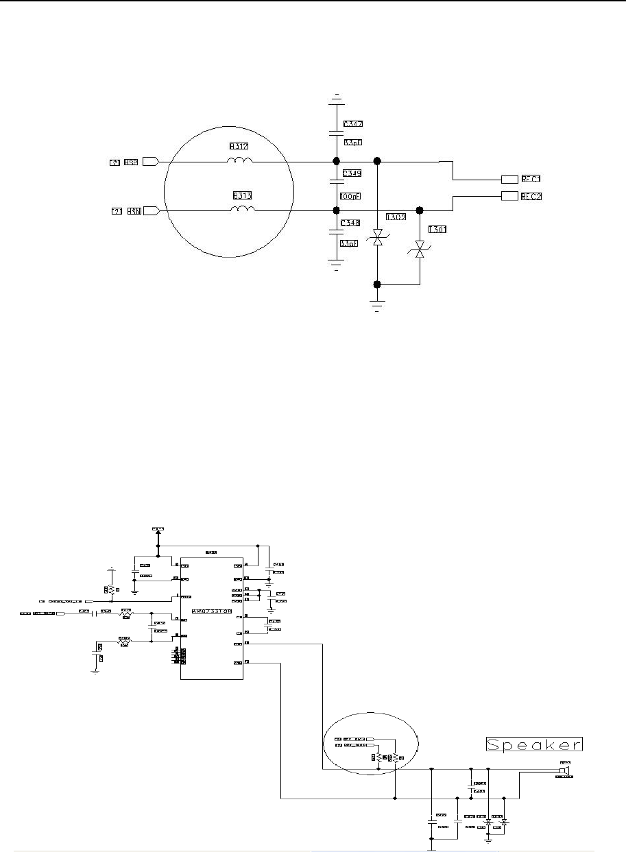
3.2.1 Micphone Circuit
Figure 3.2: Micphone
If MICPHONE useless ,first you should check R307/R315/R321/R312 ok or not,use multimeter
measure connect or not ,if not connect that not good.
Maintenance Manual
7
3.2.2 Receiver Circuit
Figure 3.3: Receiver
The receiver is part with audio output,if receiver defet,it caused by B312/B313. should measure
these two parts ok or not
3.2.3 Speaker Circuit
extraposition AudiO PA(Class K) ,this module built-in AW8733 IC chipset.
If speaker volume issue. first check speaker and R403,R404,then check AW8733 IC
Figure 3.4: Speaker
Maintenance Manual
8
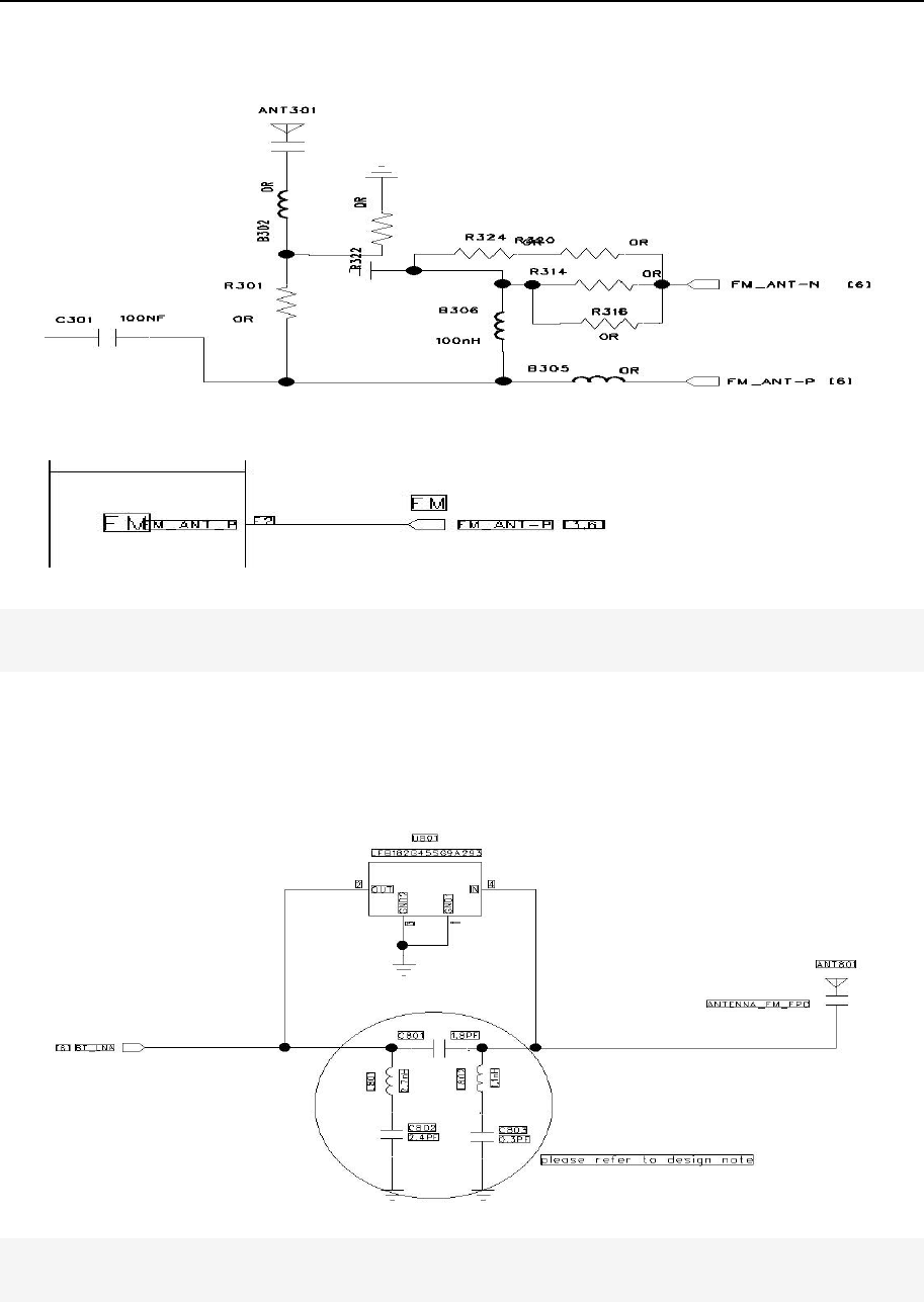
3.3 FM Module
Internal FM module ,this module built-in MTK6261-baseband chipset..
Figure 3.5
FM poor performance of the function, not active , next to match the circuit in normal circumstances,
poor FM antenna can lead to poor.
3.4 BT Module
Internal BT module ,this module built-in MTK6261-baseband chipset.
Figure 3.6
Bluetooth poor performance of the function, not active ,not find Bluetooth, next to match the circuit in
normal circumstances, poor bluetooth antenna can lead to poor.
Maintenance Manual
9
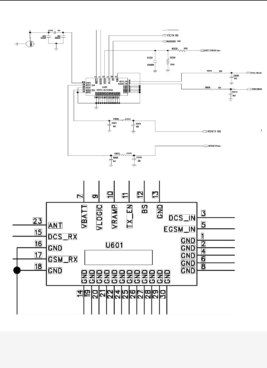
3.5 RF Module
RF Front-end Module, type HS8269S, item U601.
Figure 3.7: RF Front-end Module
RF PA is the probability of the most original failure, common faults are: no network, no signal, the signal
is weak, can dial emergency calls, etc., first replace the PA amplifier, verify failure existence or not , PA
front-end RF signal head can lead to bad signal
HS8269S
Maintenance Manual
10
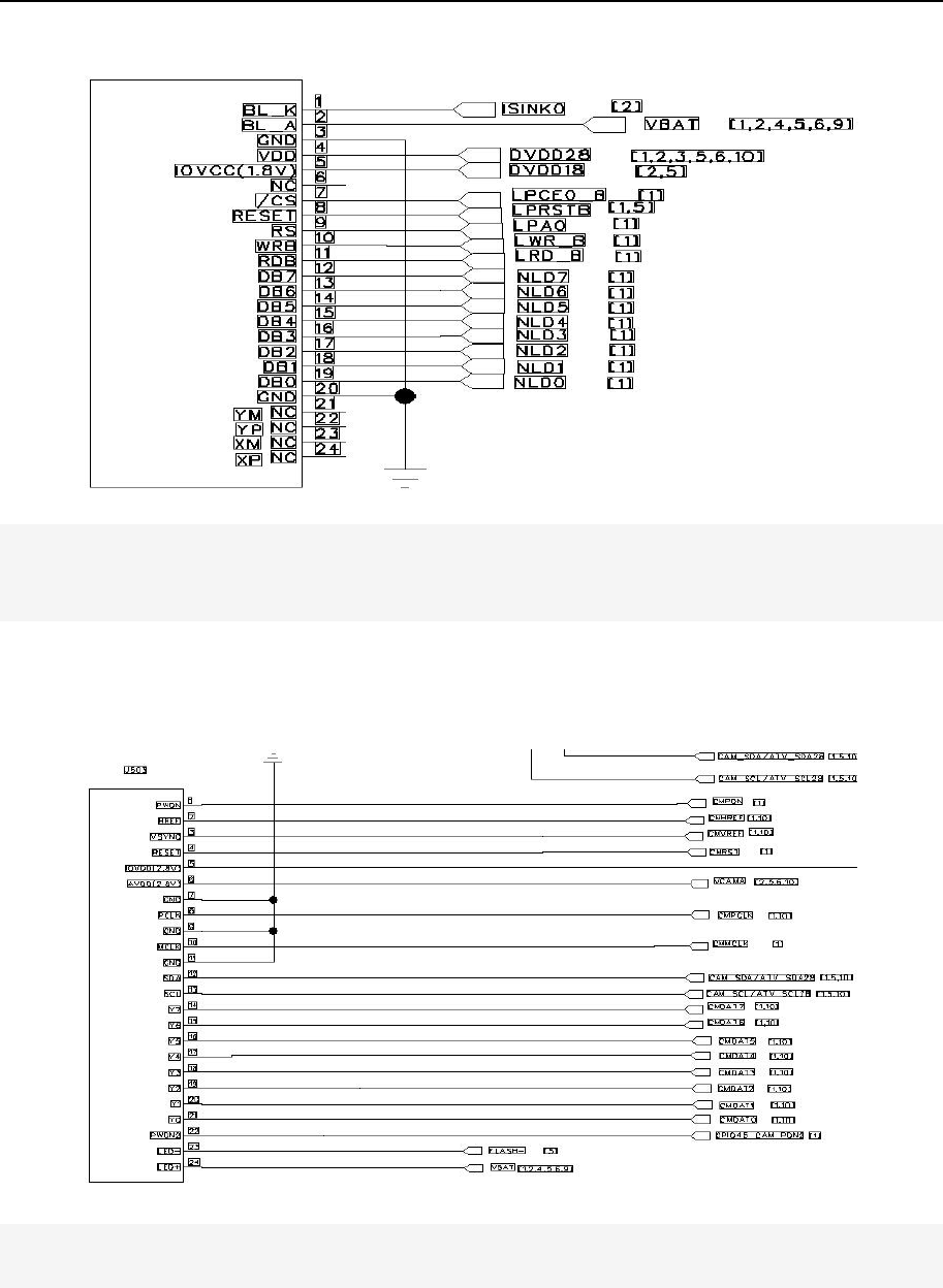
3.6 LCM Module
Figure 3.8 LCM
LCM interface is a channel connecting the motherboard and the screen, generally will not be bad, only
when improper welding operation. Note that control iron welding temperature.
3.7 CAMERA MODULE
Figure 3.9 CAMERA
CAMERA interface is connected to the motherboard and the camera position when welding OK, then,
will not cause camera failure Note that the temperature control soldering iron.
Maintenance Manual
11
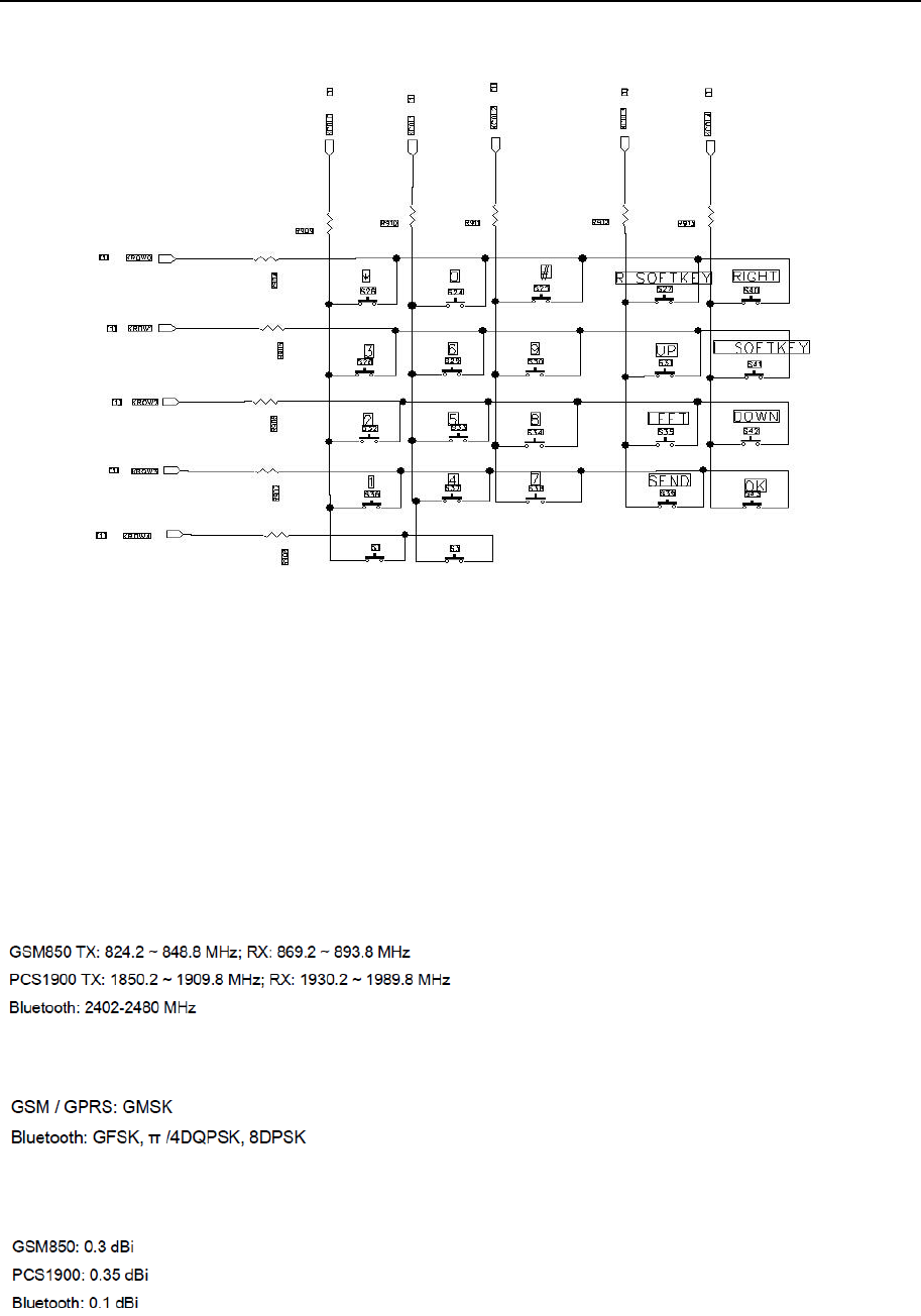
3.8 KEYPAD interface
Figure 3.10 KEYAPD4 Fault Maintenance
4.1 RF Part
Refer to function circuit Part 3.6
4.2 BB Part
Refer to function circuit.
Operating Frequency Band (RF):
Modulation mode:
Maximum of Antenna’s Gain: