Falcon M Series Service Manual New5 108006
User Manual: Falcon M-Series Service Manual Service Manual
Open the PDF directly: View PDF ![]() .
.
Page Count: 48
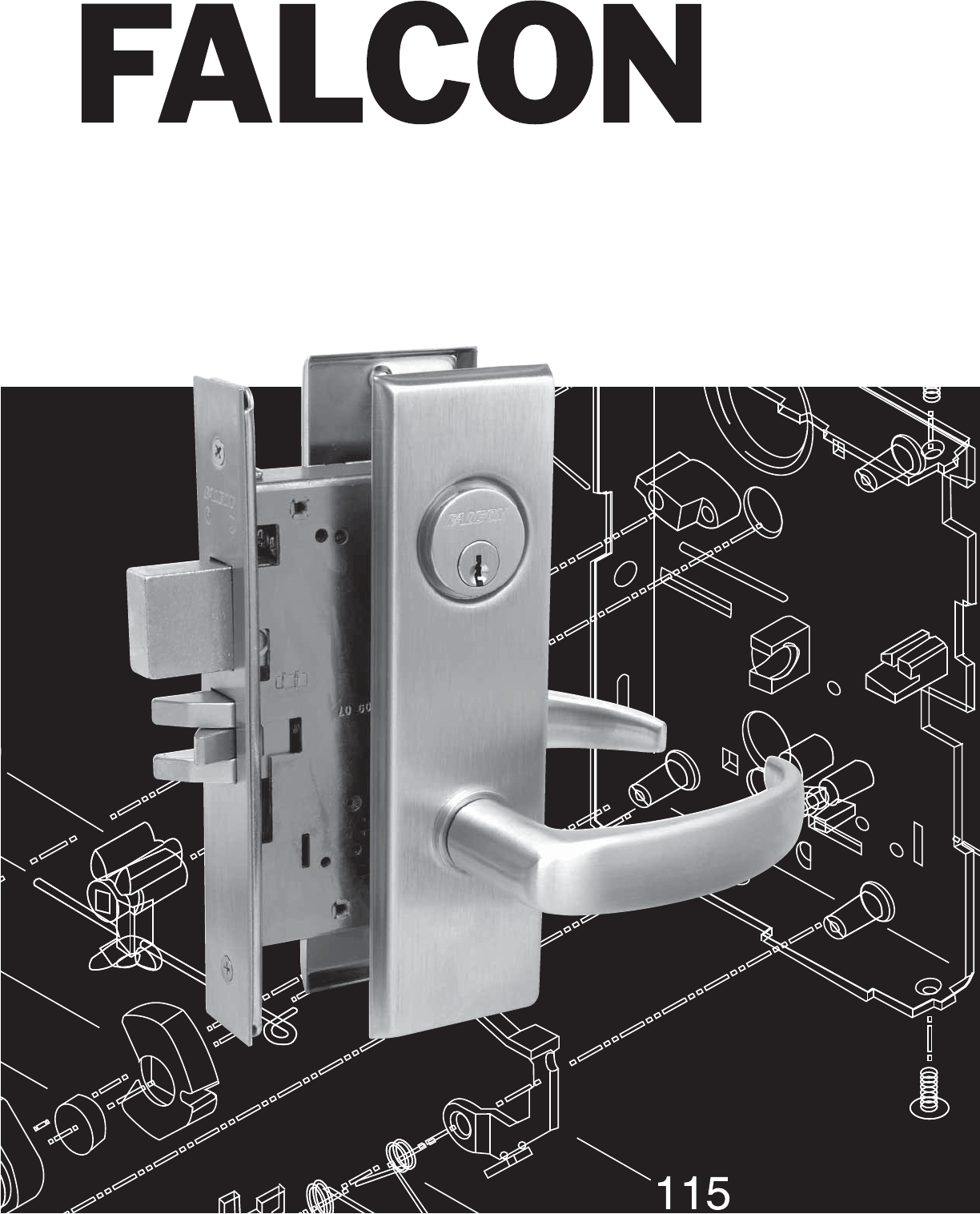
M Series Service Manual
Extra Heavy Duty, Grade 1 Mortise Lever and Knob Locks

i
M-Series Service Manual
Introduction ................................................ 1-2
Functions ................................................... 3-5
Replacement Parts for Early LM Series Lever
Trim ................................................................ 6
Trim Assemblies ....................................... 7-11
Falcon LM Series Mortise Trim ..................... 7
Falcon L-900 Series Mortise Trim ................. 8
Falcon MM Series Mortise Trim .................... 9
M Series Lever Trim Springs ....................... 10
LM12 Single Dummy Trim ........................... 11
Lock Case Assemblies .......................... 12-28
M101 Passage Latchset .............................. 12
M161 Connecting Room/Exit Latch ............. 13
M301 Privacy Lock ...................................... 14
M311 Privacy Lock ...................................... 15
M321 Privacy Lock ...................................... 16
M371/M541
Store Door Lock/Entry/Offi ce Lock .............. 17
M381/M441/M561 Entry/Restroom Lock/
Classroom Security/Classroom Lock .......... 18
M411 Asylum Lock ...................................... 19
M431/M571 Classroom Security and Deadbolt/
Dormitory Lock ............................................ 20
M451/M641/M711
Hotel/Motel Lock/Dormitory Lock/Privacy Lock
w/ Cylinder ................................................... 21
M521 Entry/Offi ce Lock ............................... 22
M531 Apartment Lock ................................. 23
M581 Storeroom/Exit Lock .......................... 24
M621 Front Door Lock ................................. 25
M851 ........................................................... 26
M881 ........................................................... 27
M911/921/931/941 Deadbolt ....................... 28
Lock Functions and Accessories ......... 29-34
Mortise Locking Units .................................. 29
Electrifi ed Mortise Chassis - Maxim w/
030173-004 Screws .................................... 30
Levers ......................................................... 31
Roses .......................................................... 31
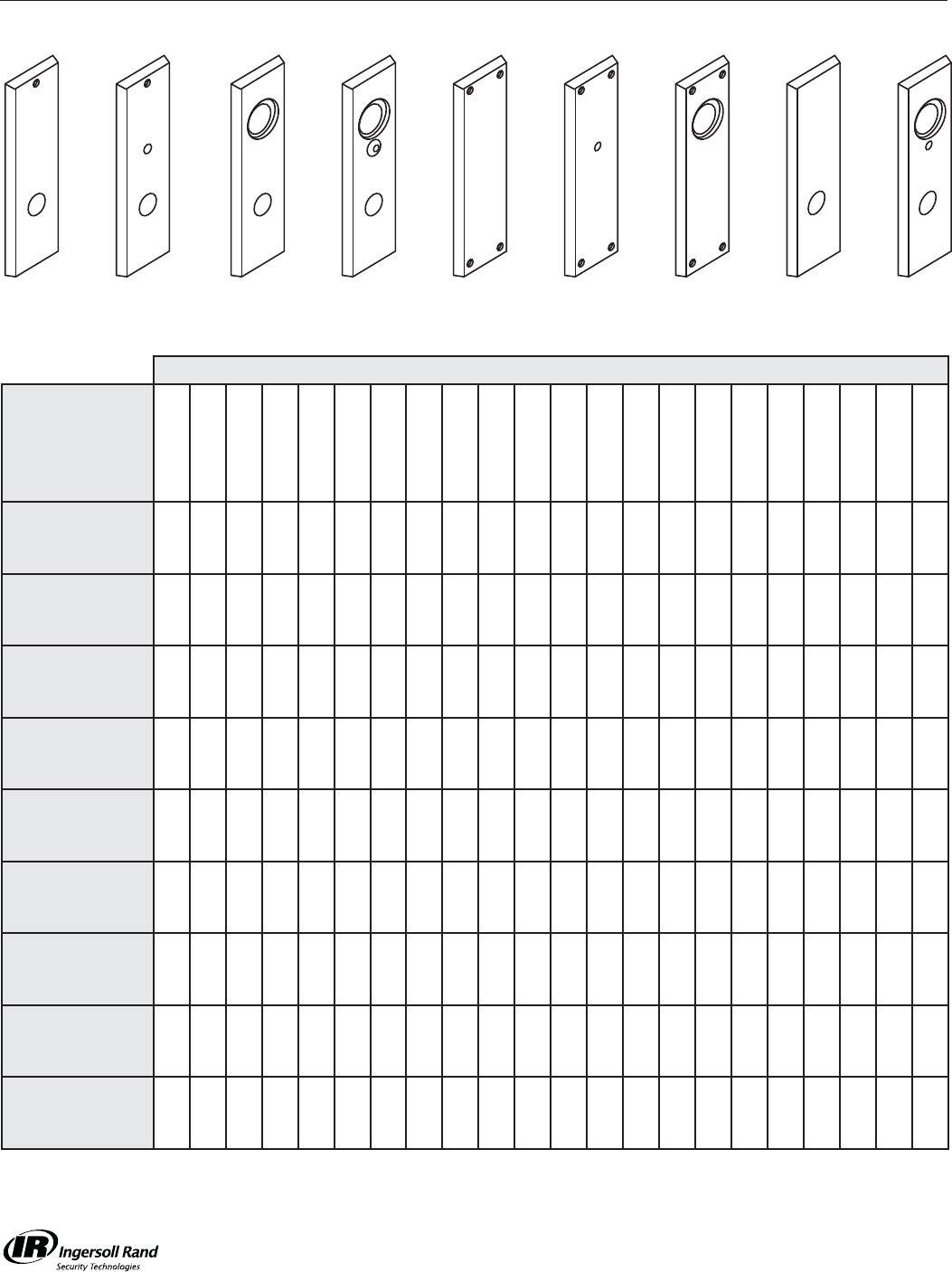
Escutcheons ............................................... 32
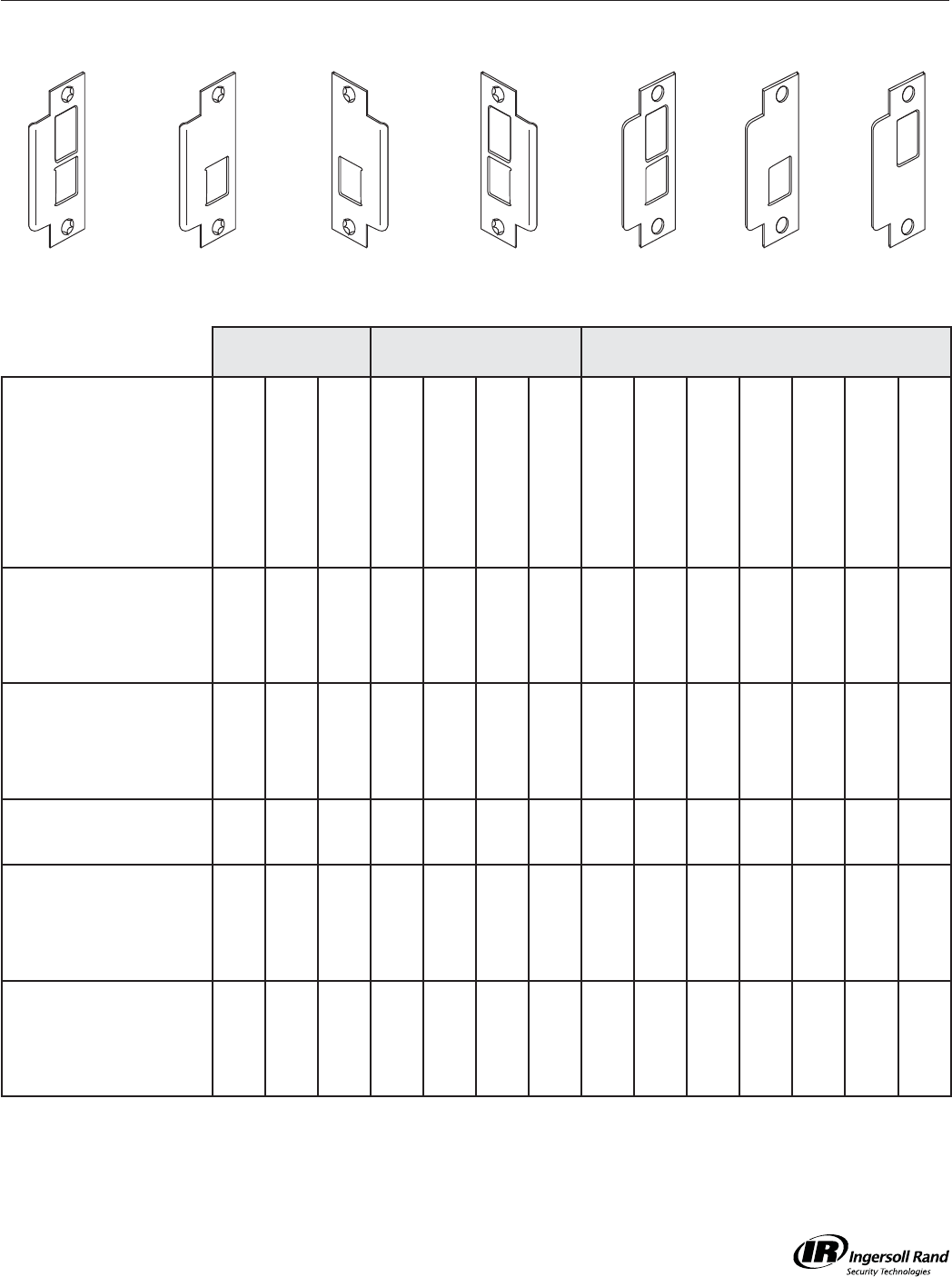
Strikes ......................................................... 33
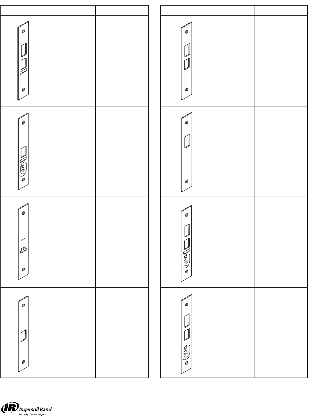
Armored Fronts/Faceplates/Sclops ............. 34
Mortise Cylinders .................................. 35-39
Mortise, Rim and Cam Lock ....................... 35
Cams ..................................................... 36-37
Cylinder Collars ..................................... 38-39
Instructions ............................................ 40-42
Reversing Hand of Locks ............................ 40
Re-Handing Instructions for Lock Trim ........ 41
Lock Re-Handing Guide ............................. 42
Table of Contents
M-Series Service Manual
1
Introduction
Introduction
This manual contains a complete listing of parts and assemblies for M-Series mortise locks manufactured by Falcon
Lock Company. This edition lists components of M-Series locks manufactured after June, 2001. All lock case covers
are labeled with dates to identify year of manufacture. Example: 12507 = the 125th day of 2007.
Exploded views of each lock function and trim assembly are provided with accompanying charts to identify parts for
replacement purposes. Exploded views of trim are shown with parts for standard size doors. In addition, this manual
provides lock trim ordering procedures, cylinder length charts by door range, and all auxiliary components of the M-
Series mortise locks.
Standard Features*
Certifi cations ANSI A156 .13, Series 1000, Grade 1 Operation, Grade 2 security, UL Listed for 3-hour fi re door.
Latch 2-piece brass mechanical anti-friction bolt, ³⁄₄” projection.
Strike 1¹⁄₄” x 4⁷⁄₈”, ANSI, Square corner, no box.
Cylinder 6-Pin solid brass, keyed 5-pin, Falcon G keyway, keyed different (KD)
Door Range 1³⁄₄” – 2¹⁄₄” standard
Keys Two, nickel silver cut keys per lock, Falcon G keyway
* Locks are furnished with standard features unless otherwise specifi ed.
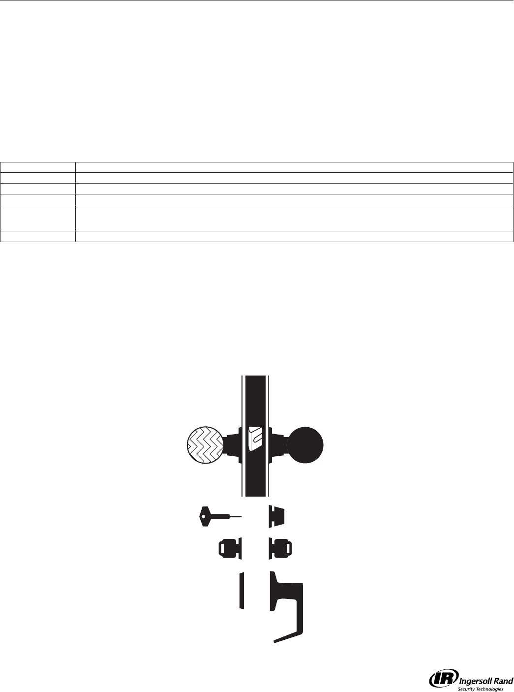
Lock Assembly Drawing Index
The Lock Assembly Drawing Index provides visual representations and textual descriptions of available functions.
Page numbers for full trim and chassis drawings are referenced.
Emergency Key
Key Key
Lever
T-Turn
K n o bK n o b
Blank Plate
Knob
Rigid Knob
T- Tu r n
M-Series Service Manual
2
Introduction
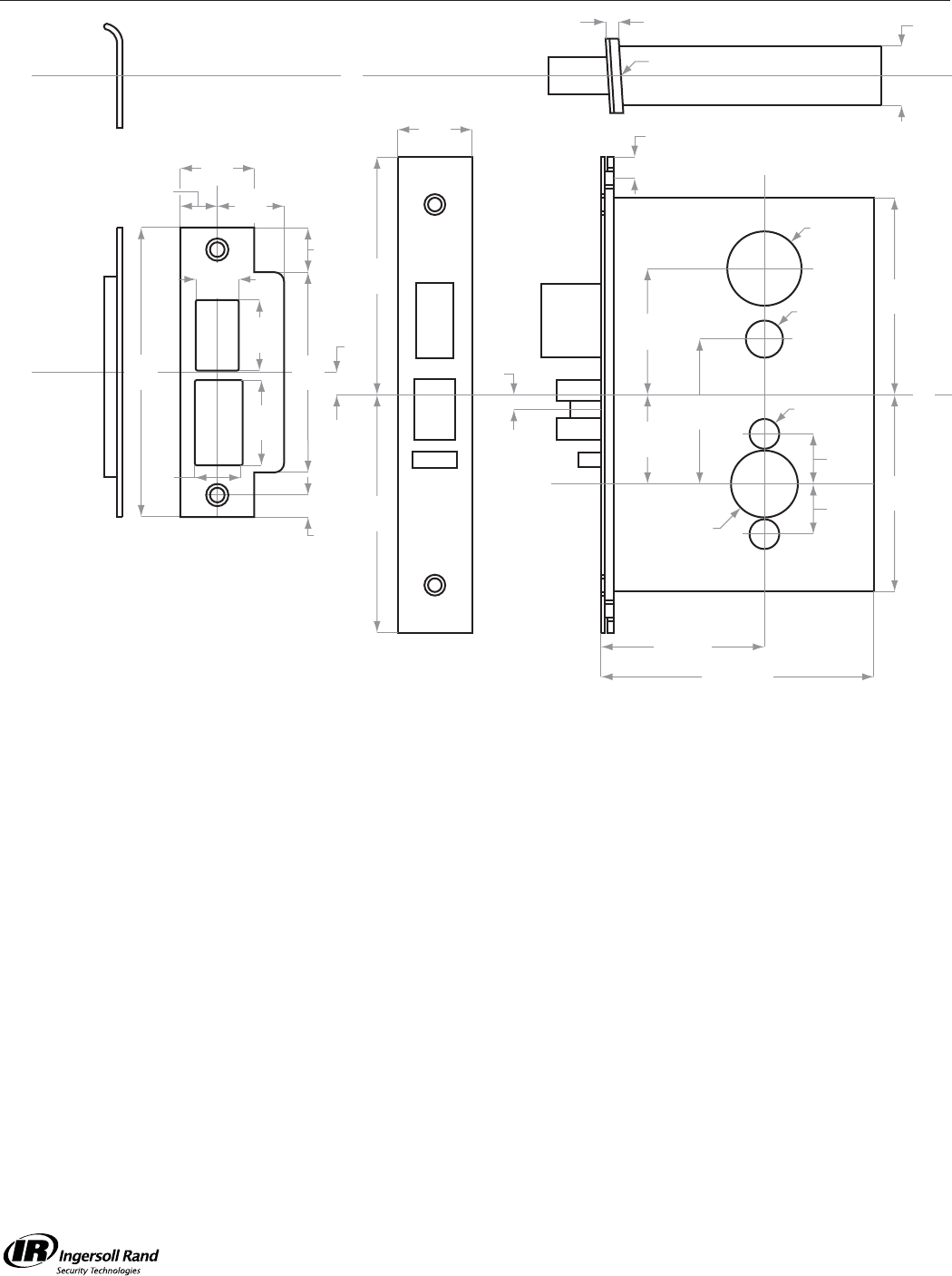
Strike
C
L
6"
(10) 56M"
(6)
C
L
4"
(102)
4"
(102)
6"
(10) C
L
Height
Line
156O"
(38)
256"
(54)
2(6QE"
(62)
3(6:O"
(21)
3(6:O"
(21)
C
L
Lock
Front
2(6"
(73)
2(6"
(73)
46" (111)
26M" (70)
Backset
(6:O"
(6)
6M"
(19)
6"
(10)
4(6"
(124)
Cylinder
cut-out
Mounting
Holes (2)
Knob or Lever
Cut-out
Turn Piece
and
Occupancy
Indicator
1. Dimensions are maximum for the product
2. Templates are not to scale
3. Standard strike is shown on each template
for dimensions only
4. Dimensions do not provide allowances for door
silencers, weather stripping, sound proofing
or other additions to door or door frames
ANSI Standards: M-Series locks meet all requirements for installations in doors and frames prepared in accordance with
ANSI specifications A156.13, 2005
Metal Doors: Suitable reinforcement is required to support lock case in center of door and to prevent door from compressing
when trim is tightened. (See ANSI A115.1)
Thick Doors: Locks for non-standard door thickness may require special instructions
Lead Lining: When M-Series locks are ordered with lead lining, add 56" (3) to the width of the mortise cut-out on the lock case cover side of
installation
Electrified Locks: Provisions must be made to route low voltage wire to the lock. Attach wires to the 6" (152) pigtail of the solenoid.
Power transfer unit and low voltage wiring are not furnished
NOTE:
Bevel 56" in 2" (3 in 51)
156M"
(32)
156M"
(32)
C
L
156"
(29)
6"
(16)
36"
(86)
6QE"
(30)
36:O"
(18)
(6QE"
(37)
56QE"
(21)
56QE"
(24)
M-Series Service Manual
3
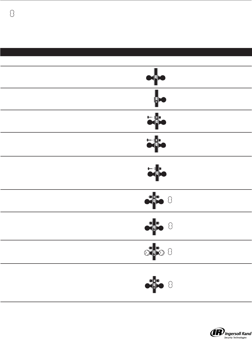
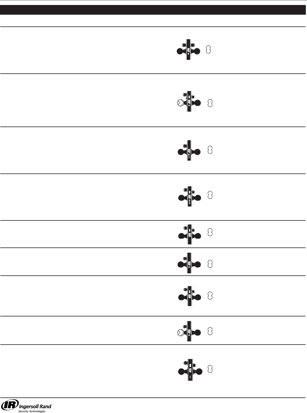
Function ANSI A156.13, 2005 Page
SCHLAGE ANSI DESCRIPTION OUTSIDE FUNCTION INSIDE FUNCTION
M101 F01-1
F01-2
Passage/Closet
Latchset
Latch bolt by levers at all
times.
Latch bolt by levers at all
times. 11
M161 -
Connecting
Room/Exit
Latch
Non-removable blank plate. Deadlocking latch bolt by
inside knob/lever. 12
M301 F02-1
F02-2 Privacy Lock
Latch bolt by knobs/levers,
emergency key (012727-
000-30).
Latch bolt by knobs/levers.
Deadbolt by turn. 13
M311 F19-1
F19-2
Privacy,
Bedroom or
Bath Lock
Latch bolt by knobs/levers.
Deadbolt by emergency key
(012727-000-30).
Latch bolt by knobs/levers.
Deadbolt by turn. Rotating
inside knob/lever retracts
both bolts.
14
M321 F22-1
F22-2 Privacy Lock
Latch bolt operated by knob/
lever from either side except
when outside knob/lever
is locked by inside T-turn.
Emergency key (012727-
000-30) furnished with lock.
Operating inside knob/lever,
closing door or operating
outside emergency release
unlocks outside knob/lever.
15
M371 F14-1
F14-2
Store Door
Lock
Latch bolt by knobs/levers.
Deadbolt by key from either
side.
Latch bolt by knobs/levers.
Deadbolt by key from either
side.
16
M381 F09-1
F09-2
Entry/Restroom
Lock
Deadlocking latch bolt by
knobs/levers except when
outside knob/lever is locked
by key inside, then by key
outside.
-17
M411 - Asylum Lock
Deadlocking latch bolt by
key from either side. Both
knobs/levers rigid.
Deadlocking latch bolt by
key from either side. Both
knobs/levers rigid.
18
M431 -
Classroom
Security Lock
with Deadbolt
Retracted by knob/lever from
either side, except when
outside lever is locked; latch
bolt then retracted by key
outside.
Retracted by knob/lever
from either side, except
when outside lever is
locked; latch bolt then
retracted by rotating lever
inside. Deadbolt thrown or
retracted by key only.
19
Functions
To order Falcon M Series locksets, please consult page 19 for ordering information and assistance.
Indicates interchangeable core available.
Catalog Number Prefi xes: Add the following prefi x for the appropriate trim style.
MM (example: MM521) = Knob Trim
LM (example: LM521) = Lever Trim
Note: If a special function is required and not listed here, please contact the factory for assistance.
M-Series Service Manual
4
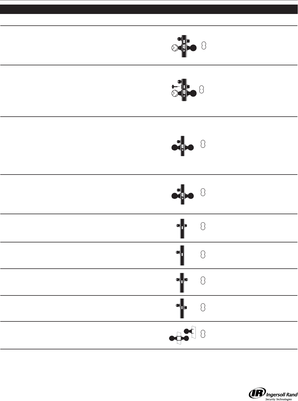
Function ANSI A156.13, 2005 Page
SCHLAGE ANSI DESCRIPTION OUTSIDE FUNCTION INSIDE FUNCTION
M441 - Classroom
Security Lock
Deadlocking latch bolt by
levers from either side
except when outer lever
is locked by key from
either side. Outer lever
is unlocked by key from
either side.
Deadlocking latch bolt by
levers from either side
except when outer lever
is locked by key from
either side. Inside lever
is always free.
17
M451 F15-1
F15-2 Hotel/Guest Lock
Deadlocking latch bolt
by key. Outside knob/
lever rigid. Deadbolt by
emergency key outside.
Projecting deadbolt
displays occupancy
indicator and shuts out all
keys except emergency.
Deadlocking latch
bolt by inside knob/
lever. Deadbolt by turn.
Rotating inside knob/
lever retracts both bolts.
Must use button to
unlock outside.
20
M521 F04-1
F04-2 Entry/Offi ce Lock
Deadlocking latch bolt by
knobs/levers except when
outside knob/lever is
locked by buttons in face,
then by key outside.
Deadlocking latch bolt
by knobs/levers except
when outside knob/lever
is locked by buttons in
face, then by key outside.
Must use button to
unlock outside.
21
M531
F10-1
F10-2
F12-1
F12-2
F20-1
Apartment
Latch bolt by knobs/levers
except when outside
knob/lever is made
inoperative by buttons in
face. Deadbolt by key
outside. Deadlocking
latch.
Deadbolt by turn.
Rotating inside knob/
lever retracts both bolts.
22
M541 F21-1
F21-2 Entry/Offi ce Lock Latch bolt by knobs/
levers. Deadbolt by key.
Latch bolt by knobs/
levers. Deadbolt by turn. 16
M561 F05-1
F05-2 Classroom Lock
Deadlocking latch bolt
by knobs/levers. Outside
knob/lever locked by key
outside.
Deadlocking latch bolt
by knobs/levers. Inside
knob/lever always free.
17
M571 F13-1
F13-2 Dormitory Lock
Latch bolt by knobs/levers
except when knob/lever
is locked by projecting
deadbolt. Key retracts
deadbolt and unlcoks
knob/lever.
Latch bolt by knobs/
levers except when
knob/lever is locked
by projecting deadbolt.
Rotating knob/lever
retracts both bolts.
19
M581 F07-1 Storeroom Lock
Deadlocking latch bolt by
key. Outside knob/lever
always rigid.
Deadlocking latch bolt by
knob/lever. 23
M621 F08 Entry Lock
Latch bolt is operated by
knob/lever from either
side except when outside
knob/lever is made
inoperative by a stop or
mechanical means other
than key. Key outside
operates both bolts.
Deadbolt is operated by
turn. Must use button to
unlock outside.
24
Functions
M-Series Service Manual
5
Function ANSI A156.13, 2005 Page
SCHLAGE ANSI DESCRIPTION OUTSIDE FUNCTION INSIDE FUNCTION
M641 - Dormitory Lock
Latch bolt by key. Outside
knob/lever rigid. Deadbolt
by key. Deadlocking latch.
Latch bolt by knob/
lever. Inside knob/
lever free. Deadbolt by
T-turn. Rotating knob/
lever retracts both bolts.
Deadlocking latch.
20
M711 - Privacy Lock
(Special)
Latch bolt operated by
key. Outside knob/lever
is always in operative.
Deadbolt operated by
emergency release. Key
outside does not operate
deadbolt. Deadlocking
latch.
Latch bolt operated by
operating knob/lever.
Deadbolt operated by
T-turn. Operating inside
knob/lever retracts both
bolts.
20
M851 - Storeroom - Fail
Safe EL
Latch bolt operated by
knob/lever from either
side except when outer
knob/lever is electrically
locked. When outer
knob/lever is locked
latch bolt retracted by
key in cylinder outside.
Deadlocking latch.
Auxiliary latch deadlocks
latchbolt when door is
closed. Inside knob/
lever is always free for
immediate exit.
25
M881 - Storeroom - Fail
Secure EU
When locked, key in
cylinder outside retracts
latch bolt.
Latch bolt operated by
knob/lever from inside
except when outer
knob/lever is electrically
unlocked, then latch bolt
from either side.
26
M911 - Classroom Safety
Deadlock
Deadbolt retracted by key.
Deadbolt projected by key.
Deadbolt retracted by
turn. 27
M921 F18-1
F18-2 Deadlock Deadbolt by key. - 27
M931 F16-1
F16-2 Deadlock Deadbolt by key. Deadbolt by key. 27
M941 F17-1
F17-2 Deadlock Deadbolt by key. Deadbolt by turn. 27
M12/M18 - Dummy Trim Single or double available. -
Functions
M-Series Service Manual
6
Replacement Parts for Early LM Series Lever Trim
Call Out
Number Description Part Number
Call Out
Number Description Part Number
1 Bushing 030067-000-50 22 Lever Return Spring, Green 030057-002-30
6 Hex Nut 030282-000-30 23 Lever Stop 030054-001-30
7 Inner Insert 030051-001-55 24 Lock Washer 030284-000-60
8 Inner Insert Assy, All Other
Levers
A30073-003-00 44 Spindle & Spring Assembly A21245-000-00
15 Inner Trim Shank 030053-001-30
Trim and Accessories
44 6
24
23
22
71
15
8
Inside
M-Series Service Manual
7
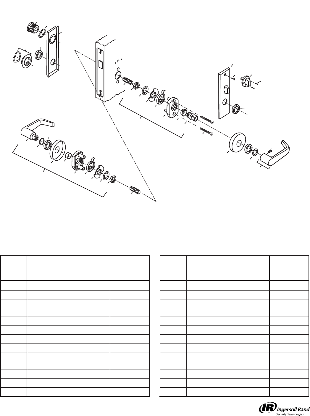
Falcon LM Series Mortise Trim
Trim Assemblies
44 6
24
23
22
71
15
10
Inside
44
6
24
23
32
30 or 31
33
2
36 1
26 22
38
17
13
36
42
2
2
4
40 46
39
2
3
25 45
5
Call Out
Number Description Part Number
Call Out
Number Description Part Number
1 Bushing 030067-000-50 25 Mortise Cylinder w/9894-1 Cam 985 w/9894-1
2 Collar 030059-000 * 26 Outer Insert, Tapped 030051-000-55
3 Collar Assy, Sectional A08794-000 * 30 Outer Lever Assy, Dane Gala A30068-00D *
4 Escutcheon w/T-Turn, Napa A30203-000 * 31 Outer Lever Assy, Dane Napa A30072-05D *
5 Escutcheon, Napa 030066-005 * 32 Outer Lever, Dane 021280-000 *
6 Hex Nut 030282-000-30 33 Outer Washer 030205-002-50
7 Inner Insert 030051-001-55 36 Rose 030052-000 *
10 Inner Insert Assy A30073-001-00 38 Screw, 10-32 x 2 FHMS 030069-032-30
13 Inner Lever Assy, Dane (shown)** A30202-00D * 39 Screw, 6 x 1/2 FHSMS 002073-000 *
15 Inner Trim Shank 030053-001-30 40 Screw, 6 x 3/4 OHSMS 002074-012 *
17 Inner Washer 030205-001-50 42 Set Screw, 1/4-28 x 1/4 030283-004-30
22 Lever Return Spring 030057-002-30 44 Spindle & Spring Assembly A21245-000-00
23 Lever Stop 030054-001-30 45 Spring Washer, Cylinder 008789-001-60
24 Lock Washer 030284-000-60 46 T-Turn Assy, Sectional A20336-000 *
*= Finish or Specify Finish on All **For other lever options, see page
M-Series Service Manual
8
Falcon L-900 Series Mortise Trim
Call Out
Number Description Part Number
25 Mortise Cylinder w/9894-1
Cam
985 w/9894-1
39 Screw, 6 x 1/2 FHSMS 002073-000 *
45 Spring Washer, Cylinder 008789-001-60
46 T-Turn Assy, Sectional A20336-000 *
49 M911 Classroom Thumbturn 973 (RH) 974 (LH)
Inside
46
39
25 45
Inside
49
25 45
Inside
Inside
25 45
25
25 45
941
921 931
911
45
*= Finish or Specify Finish on All
M-Series Service Manual
9
Falcon MM Series Mortise Trim
Call Out
Number Description Part Number
Call Out
Number Description Part Number
1 Bushing 030067-000-50 29 Outer Knob Assy, Hana Napa A30074-05H *
2 Collar 030059-000 * 33 Outer Washer 030205-002-50
3 Collar Assy, Sectional A08794-000 * 35 Retainer Ring 002939-000-30
4 Escutcheon w/T-Turn, Napa A30203-000 * 36 Rose 030052-000 *
5 Escutcheon, Napa 030066-005 38 Screw, 10-32 x 2 FHMS 030069-032-30
7 Inner Insert 030051-001-55 39 Screw, 6 x 1/2 FHSMS 002073-000 *
11 Inner Insert Assy, Knob A30078-000-00 40 Screw, 6 x 3/4 OHSMS 002074-012 *
12 Inner Knob Assy, Hana A30065-00H * 42 Set Screw, 1/4-28 x 1/4 030283-004-30
14 Inner Trim Shank 030053-000-30 43 Spacer 030063-000-30
17 Inner Washer 030205-001-50 44 Spindle & Spring Assembly A21245-000-00
25 Mortise Cylinder w/9894-1 Cam 985 w/9894-1 45 Spring Washer, Cylinder 008789-001-60
26 Outer Insert, Tapped 030051-000-55 46 T-Turn Assy, Sectional A20336-000 *
27 Outer Knob Assy, Hana A30138-00H * 47 Washer 030163-000-60
28 Outer Knob Assy, Hana Gala A30077-00H * *= Finish or Specify Finish on All
Trim Assemblies
2
4
40 46
39
2
3
25
45
5
44
38
35
47
43
17
12
36
42
71
14
11
2
44
35
47
27
28 or 29
33
2
36 1
26 43

M-Series Service Manual
10
M-Series Lever Trim Springs
030057-002-30 Yellow Color (.052 Thick Wire)
Replacement for Green Springs
Used on: Avalon All Materials
Dane All Materials
Quantum All Materials
Sutro All Materials First used in July 1995
Trim Accessories
M-Series Service Manual
11
Parts List - LM12 AG
LM12 Single Dummy Trim
Lock Functions and Accessories
20
2
36
37
15
1
19
34
24
6
18 42
Call Out
Number Description Part Number
Call Out
Number Description Part Number
1 Bushing 030067-000-50 20 Lever Assembly, Avalon** A30202-00A *
2 Collar 030059-000 * 24 Lock Washer 030284-000-60
6 Hex Nut 030282-000-30 34 Plate, Dummy 030054-002-30
15 Inner Trim Shank 030053-001-30 36 Rose 030052-000 *
18 Insert Assembly A30257-04L-00 37 Screw, 10 x 1 FHSM (2) 030220-016-30
19 Insert, Dummy 030051-004-55 42 Set Screw, 1/4-28 x 1/4 030283-004-30
*= Finish or Specify Finish on All
** For other lever options, see page 25
Lock Case Assemblies
M-Series Service Manual
12
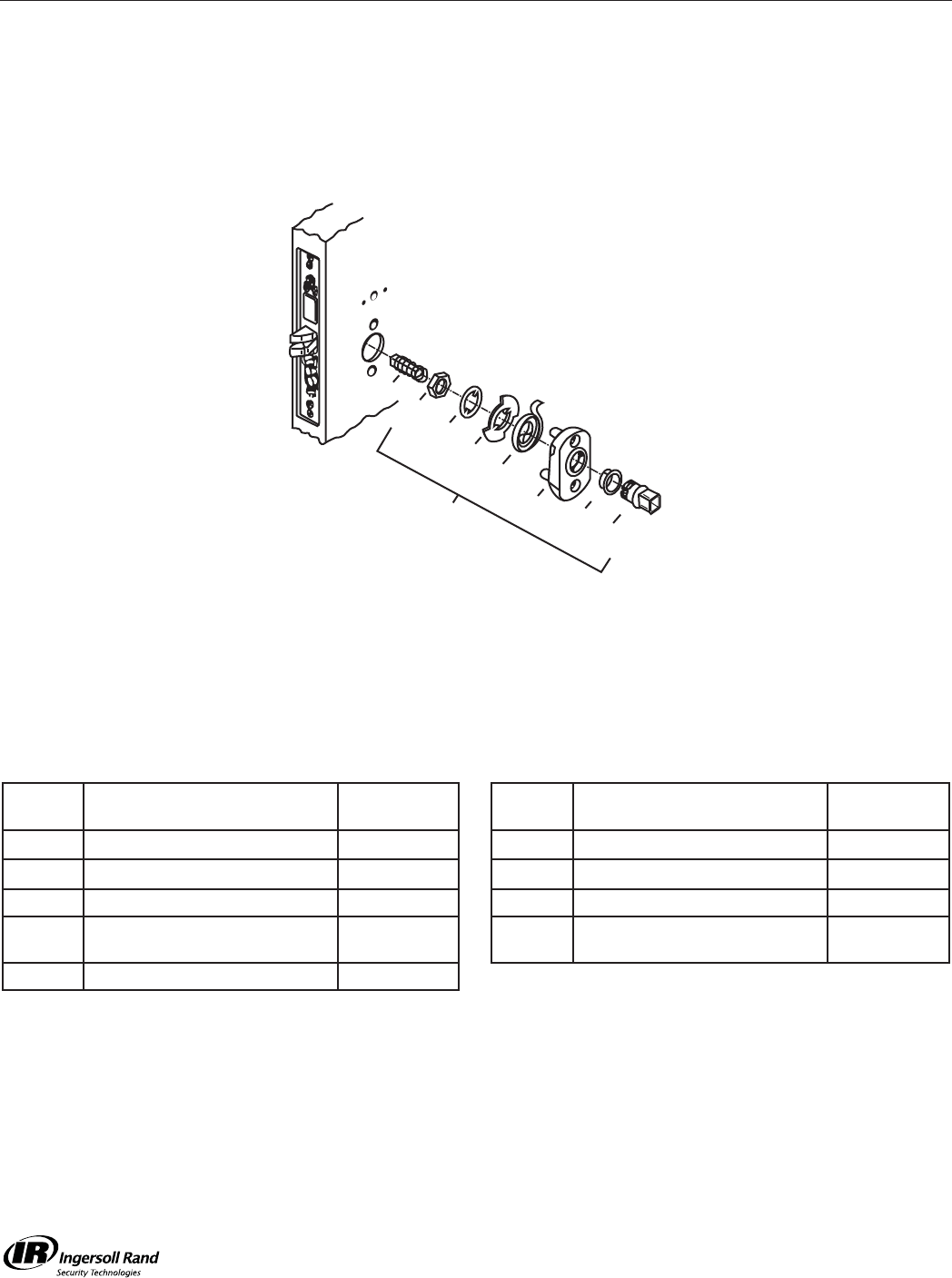
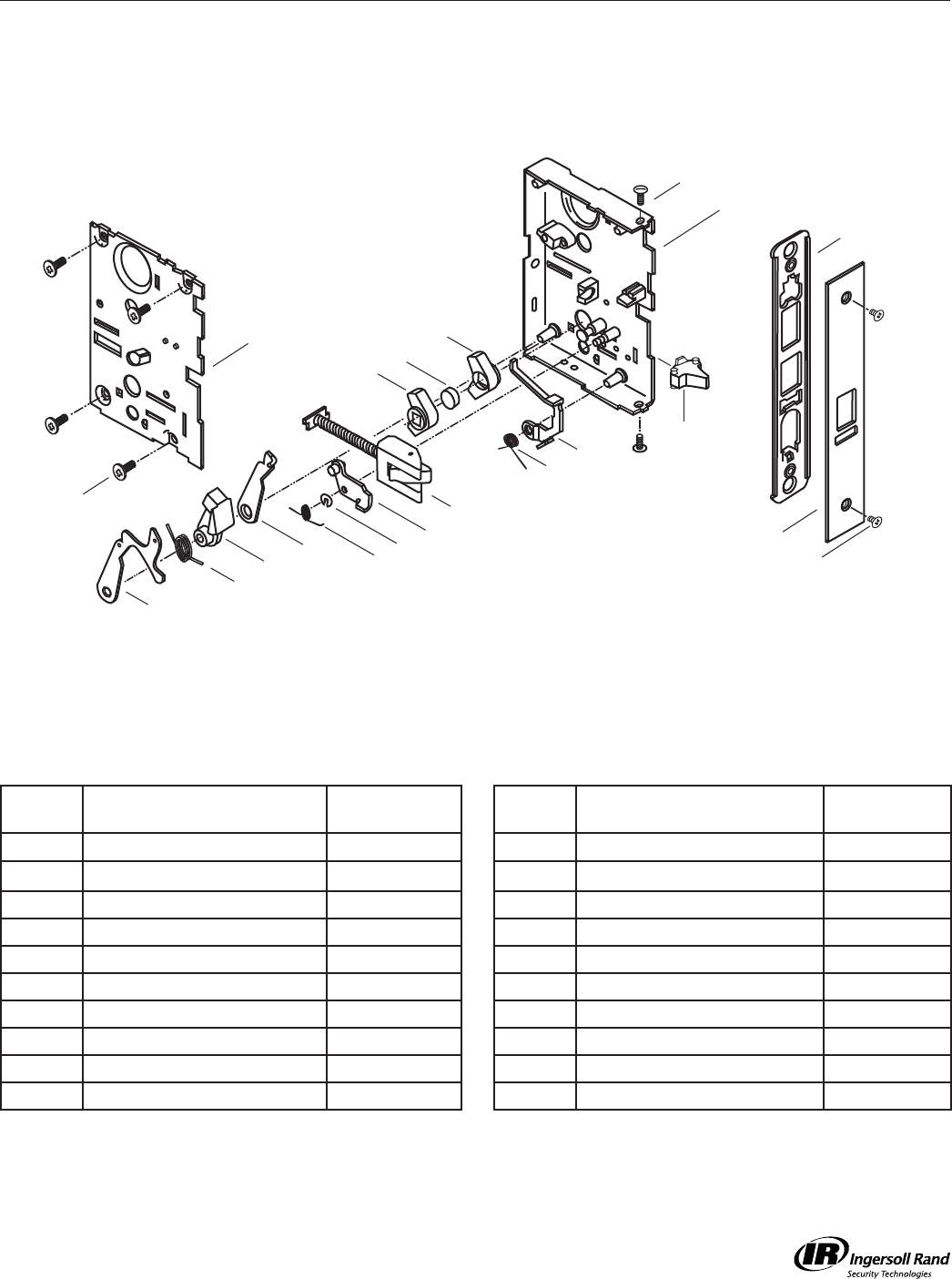
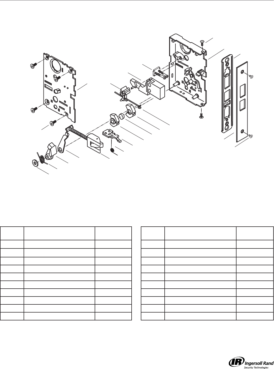
Parts List - A20800-30F * Locking Unit M101
M101 Passage Latchset
A20800-000-626
Call Out
Number Description Part Number
Call Out
Number Description Part Number
50 Arm, Lower Retract 020645-000-30 114 Latch Bolt Assy
A20639-004-626
59 Case Assy A20580-001-00 129 Screw 8-32 x 1/4 K110-020
77 Coupling 020646-000-30 130 Screw 8-32 x 3/8 (4) 002801-006-30
80 Cover Assy, Not Tapped A30875-000-00 131 Screw 8-32 x 3/8 (2) 002932-000-30
90 Faceplate 020100-000 * 137 Spacer Hub 020674-000-30
102 Front Plate 1-1/4” Wide 021349-000-30 153 Spring, Retract Arm 020666-000-60
105 Hub, Non-Locking (2) 020642-000-30 159 Washer, Flat 002900-000-30
*= Finish or Specify Finish on All
129
90
102
130
80
59
131
105
137
105
114
50
77
153
159
RIGHT HAND OR LEFT HAND REVERSE SHOWN
Lock Case Assemblies M-Series Service Manual
13
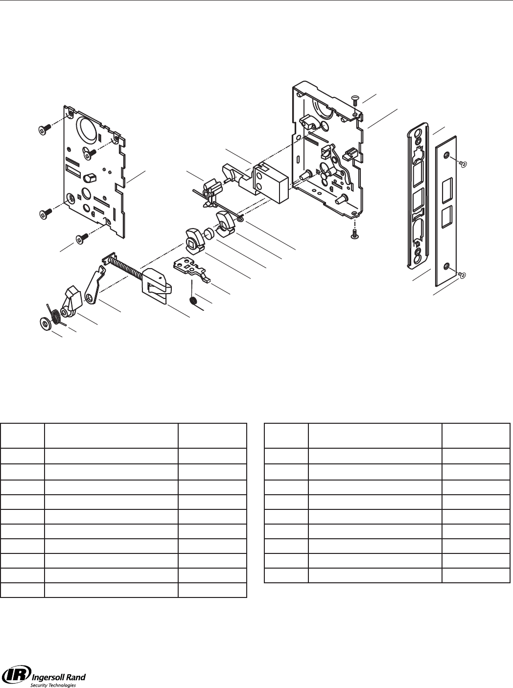
Parts List - A30842-30F* Locking Unit M161
M161 Connecting Room/Exit Latch
A30842-000-626
Call Out
Number Description Part Number
Call Out
Number Description Part Number
50 Arm, Lower Retract 020645-000-30 114 Latch Bolt Assy
A20639-004-626
52 Arm, Upper Retract 020633-000-30 115 Lever 020575-000-30
54 Bar, Deadlocking
020579-000-630
128 Ring, Truarc 005347-000-30
55 Blocker Assy A20957-000-00 129 Screw 8-32 x 1/4 (2) K110-020
68 Case Assy A30877-00-00 130 Screw 8-32 x 3/8 (4) 002801-006-30
77 Coupling
020646-000-30
131 Screw 8-32 x 3/8 (2) 002932-000-30
80 Cover Assy, Not Tapped A30875-000-00 137 Spacer Hub 020674-000-30
89 Faceplate 020099-01U * 142 Spring, Blocker 020492-000-60
102 Front Plate 1-1/4” Wide 021349-000-30 147 Spring, DL 020595-001-60
105 Hub, Non-Locking (2) 020642-000-30 153 Spring, Retract Arm 020666-000-60
*= Finish or Specify Finish on All
130
80
129
89
102
RIGHT HAND OR LEFT HAND REVERSE SHOWN
68
131
105
137
105
114
147
115
54
55
142
128
52
50
77
153
Lock Case Assemblies
M-Series Service Manual
14
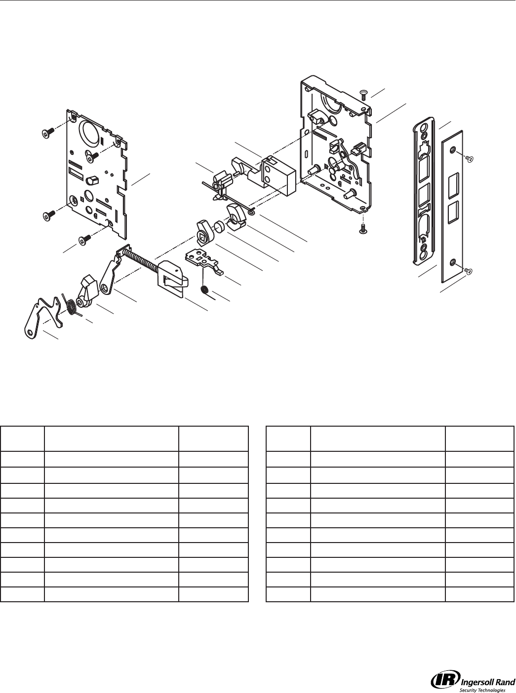
Parts List - A20806-000-626 Locking Unit M301
M301 Privacy Lock
A20806-000-XXX
Call Out
Number Description Part Number
Call Out
Number Description Part Number
50 Arm, Lower Retract 020645-000-30 129 Screw 8-32 x 1/4 (2) K110-020
64 Case Assy A20588-001-00 130 Screw 8-32 x 3/8 (4) 002801-006-30
77 Coupling 020646-000-30 131 Screw 8-32 x 3/8 (2) 002932-000-30
79 Blocker Assy A23204-000-00 134 Slide, Locking Hub 020572-000-30
84 Deadbolt 1”
030147-000-626
137 Spacer Hub 020674-000-30
91 Faceplate UL 020109-000 * 144 Spring, Deadbolt 020641-000-30
102 Front Plate 1-1/4” Wide 021349-000-30 153 Spring, Retract Arm 020666-000-60
104 Hub, Locking 020643-000-30 158 Torsion Spring 021111-001-60
109 Hub, T-Turn 020652-001-30 159 Washer, Flat 002900-000-30
114 Latch Bolt Assy
A20639-004-626
*= Finish or Specify Finish on All
130
79
129
91
102
RIGHT HAND OR LEFT HAND REVERSE SHOWN
64
131
104
144
104
137
158
134
84
109
159
50 114
77
153
Lock Case Assemblies M-Series Service Manual
15
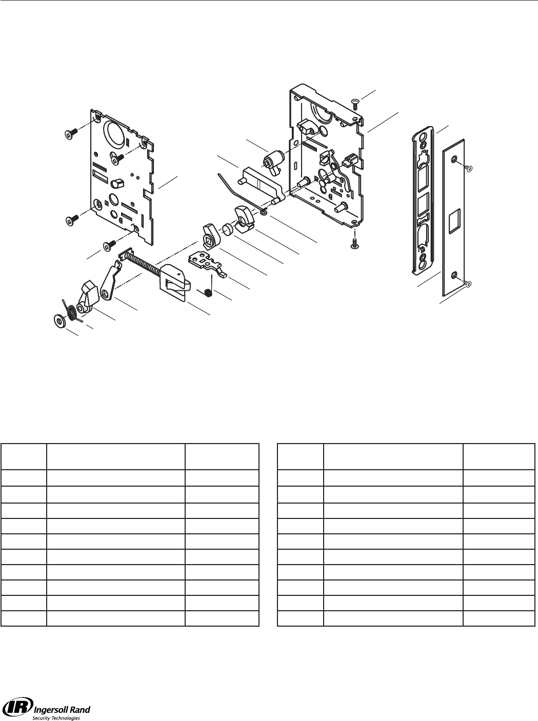
Parts List - A21863-30F * Locking Unit M311
M311 Privacy Lock
A21841-000-626
Call Out
Number Description Part Number
Call Out
Number Description Part Number
50 Arm, Lower Retract 020645-000-30 109 Hub, T-Turn 020652-001-30
52 Arm, Upper Retract 020633-000-30 114 Latch Bolt Assy
A20639-004-626
64 Case Assy, Not Tapped A20588-001-00 129 Screw 8-32 x 1/4 (2) K110-020
77 Coupling 020646-000-30 130 Screw 8-32 x 3/8 (4) 002801-006-30
79 Cover Assy, Threaded A23204-000-00 131 Screw 8-32 x 3/8 (2) 002932-000-30
84 Deadbolt 1”
030147-000-626
134 Slide, Locking Hub 020572-000-30
91 Faceplate UL 020109-000 * 137 Spacer Hub 020674-000-30
102 Front Plate 1-1/4” Wide 021349-000-30 144 Spring, Deadbolt 020641-000-30
104 Hub, Locking 020643-000-30 153 Spring, Retract Arm 020666-000-60
105 Hub, Non-Locking 020642-000-30 158 Torsion Spring 021111-001-60
*= Finish or Specify Finish on All
130
79
129
91
102
RIGHT HAND SHOWN
64
131
104
144
105137
158
134
84
109
50
114
77
52
153
Lock Case Assemblies
M-Series Service Manual
16
Parts List - A30539-30F * Locking Unit M321
M321 Privacy Lock
A30539-000-626
Call Out
Number Description Part Number
Call Out
Number Description Part Number
50 Arm, Lower Retract 020645-000-30 129 Screw 8-32 x 1/4 (2) K110-020
72 Case Assy, Not Tapped A30544-000-00 130 Screw 8-32 x 3/8 (4) 002801-006-30
77 Coupling 020646-000-30 131 Screw 8-32 x 3/8 (2) 002932-000-30
79 Cover Assy, Not Tapped A23204-000-00 133 Slide, Locking 030535-000-55
90 Faceplate 020100-000 * 134 Slide, Locking Hub 020572-000-30
102 Front Plate 1-1/4” Wide 021349-000-30 137 Spacer Hub 020674-000-30
103 Hub & Pin Assy A30534-000-00 151 Spring, Locking Slide 030382-000-30
104 Hub, Locking 020643-000-30 153 Spring, Retract Arm 020666-000-60
105 Hub, Non-Locking 020642-000-30 158 Torsion Spring 021111-001-60
114 Latch Bolt Assy
A20639-004-626
159 Washer, Flat 002900-000-30
*= Finish or Specify Finish on All
130
79
RIGHT HAND SHOWN
72
131
104
151
105
137
158
134
159
50 114
133
103
77
153
129
90
102
Lock Case Assemblies M-Series Service Manual
17
Parts List - A20809-000-626 Locking Unit M371/541
M371 Store Door Lock
M541 Entry/Offi ce Lock
A20809-000-626
Call Out
Number Description Part Number
Call Out
Number Description Part Number
50 Arm, Lower Retract 020645-000-30 121 Retainer Assy, Cyl A21209-000-00
64 Case Assy A20588-001-00 129 Screw 8-32 x 1/4 (2) K110-020
77 Coupling 020646-000-30 130 Screw 8-32 x 3/8 (4) 002801-006-30
79 Cover Assy A23204-000-00 131 Screw 8-32 x 3/8 (2) 002932-000-30
84 Deadbolt 1”
030147-000-626
134 Slide, Locking Hub 020572-000-30
91 Faceplate 020109-000 * 137 Spacer Hub 020674-000-30
102 Front Plate 1-1/4” Wide 021349-000-30 144 Spring, Deadbolt 020641-000-30
104 Hub, Locking (2) 020643-000-30 153 Spring, Retract Arm 020666-000-60
109 Hub, T-Turn 020652-001-30 158 Torsion Spring 021111-001-60
114 Latch Bolt Assy
A20639-004-626
159 Washer, Flat 002900-000-30
*= Finish or Specify Finish on All
129
91
102
50 114
158
134
104
137
104
144
109
84
121
77
159
153
64
131
RIGHT HAND OR LEFT HAND REVERSE SHOWN
130
79
Lock Case Assemblies
M-Series Service Manual
18
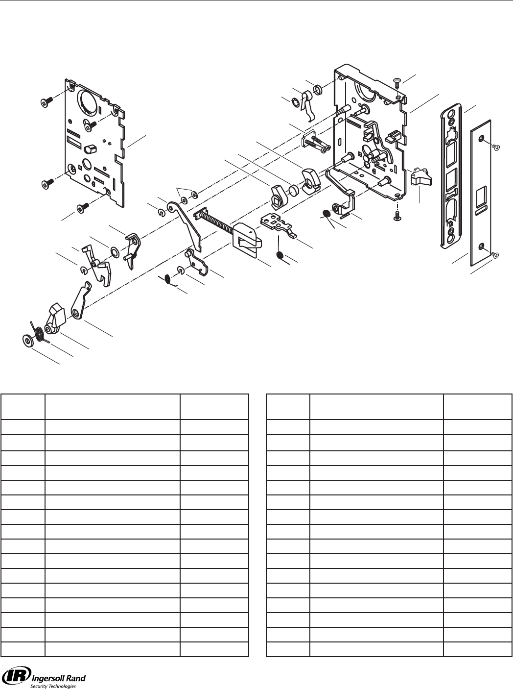
Parts List - A30812-30F * Locking Unit M381/561
M381 Entry/Restroom Lock
M441 Classroom Security
M561 Classroom Lock
A30812-000-626
Call Out
Number Description Part Number
Call Out
Number Description Part Number
48 Arm, Blocker Release 020491-000-30 121 Retainer Assy, Cyl A21209-000-00
51 Arm, Lower Retract 021185-000-30 122 Retaining Ring 002975-000-30
54 Bar, Deadlocking 020579-000-630 128 Ring, Truarc (3) 005347-000-30
55 Blocker Assy A20957-000-00 129 Screw 8-32 x 1/4 (2) K110-020
60 Case Assy A20583-002-00 130 Screw 8-32 x 3/8 (4) 002801-006-30
77 Coupling 020646-000-30 131 Screw 8-32 x 3/8 (2) 002932-000-30
79 Cover Assy A23204-000-00 134 Slide, Locking Hub 020572-000-30
82 Cylinder Lever Assy A20598-000-00 136 Spacer, Spring 021026-000-10
89 Faceplate 020099-01U * 137 Spacer Hub 020674-000-30
102 Front Plate 1-1/4” Wide 021349-000-30 140 Spacer, Washer (2) 020447-000-10
104 Hub, Locking 020643-000-30 142 Spring, Blocker 020492-000-60
105 Hub, Non-Locking 020642-000-30 147 Spring, DL 020595-001-60
114 Latch Bolt Assy A20639-004-626 153 Spring, Retract Arm 020666-000-60
115 Lever 020575-000-30 158 Torsion Spring 021111-001-60
117 Lever Spring 020086-000-30 159 Washer, Flat 002900-000-30
118 Lever, Cyl 020660-000-30 160 Washer, Flat 004315-000-60
*= Finish or Specify Finish on All
129
89
102
RIGHT HAND SHOWN
51
142
54
128
128
12848
105 137
104
140
118
160
159
82
55
158
134
147
115
114
77
153
60
131
121
122
117
136
130
79

Lock Case Assemblies M-Series Service Manual
19
Parts List - A30815-30F * Locking Unit M411
M411 Asylum Lock
A30815-000-626
Call Out
Number Description Part Number
Call Out
Number Description Part Number
48 Arm, Blocker Release 020491-000-30 121 Retainer Assy. Cyl A21209-000-00
54 Bar, Deadlocking
020579-000-630
128 Ring, Truarc (3) 005347-000-30
55 Blocker Assy A20957-000-00 129 Screw 8-32 x 1/4 (2) K110-020
61 Case Assy A20584-002-00 130 Screw 8-32 x 3/8 (4) 002801-006-30
79 Cover Assy A23204-000-00 131 Screw 8-32 x 3/8 (2) 002932-000-30
82 Cylinder Lever Assy A20598-000-00 132 Sleeve, Lever Post 020659-000-10
89 Faceplate 020099-01U * 137 Spacer Hub 020674-000-30
102 Front Plate 1-1/4” Wide 021349-000-30 140 Spacer, Washer (2) 020447-000-10
104 Hub, Locking (2) 020643-000-30 142 Spring, Blocker 020492-000-60
114 Latch Bolt Assy
A20639-004-626
147 Spring, DL 020595-001-60
115 Lever 020575-000-30
*= Finish or Specify Finish on All
RIGHT HAND OR LEFT HAND REVERSE SHOWN
129
89
102
142
128
128
128 48
104137
104
140
82
55 114
147
115
132
61
131
121
54
130
79
Lock Case Assemblies
M-Series Service Manual
20
*= Finish or Specify Finish on All
Parts List - A20827-000-626
M431 Classroom Security and Deadbolt
M571 Dormitory Lock
A20827-000-626
Call Out
Number Description Part Number
Call Out
Number Description Part Number
50 Arm, Lower Retract 020645-000-30 121 Retainer Assy, Cyl A21209-000-00
64 Case Assy A20588-001-00 124 Retract Arm Assy A20601-002-00
77 Coupling 020646-000-30 129 Screw 8-32 x 1/4 (2) K110-020
79 Cover Assy A23204-000-00 130 Screw 8-32 x 3/8 (4) 002801-006-30
84 Deadbolt 1”
030147-000-626
131 Screw 8-32 x 3/8 (2) 002932-000-30
91 Faceplate 020109-000 * 134 Slide, Locking Hub 020572-000-30
102 Front Plate 1-1/4” Wide 021349-000-30 137 Spacer Hub 020674-000-30
104 Hub, Locking 020643-000-30 143 Spring, Cyl Lever 021011-000-60
105 Hub, Non-Locking 020642-000-30 144 Spring, Deadbolt 020641-000-30
109 Hub, T-Turn 020652-001-30 153 Spring, Retract Arm 020666-000-60
114 Latch Bolt Assy
A20639-004-626
158 Torsion Spring 021111-001-60
116 Lever & Pin Assy A20602-000-00
RIGHT HAND SHOWN
91
102
129
114
158
134
64
131
121
84
109
143
144
104
137
105
124
116
77
153
50
130
79
Lock Case Assemblies M-Series Service Manual
21
Parts List - A30836-30F * Locking Unit M451/631/641/711
M451 Hotel/Motel Lock
M641 Dormitory Lock
M711 Privacy Lock w/Cyl
A30836-000-626
Call Out
Number Description Part Number
Call Out
Number Description Part Number
50 Arm, Lower Retract 020645-000-30 115 Lever 020575-000-30
54 Bar, Deadlocking
020579-000-630
116 Lever & Pin Assy A20602-000-00
55 Blocker Assy A20957-000-00 121 Retainer Assy. Cyl A21209-000-00
56 Blocker, Button 020577-000-30 124 Retract Arm Assy A20601-002-00
62 Case Assy A20586-002-00 128 Ring, Truarc 005347-000-30
77 Coupling 020646-000-30 129 Screw 8-32 x 1/4 (2) K110-020
79 Cover Assy A23204-000-00 130 Screw 8-32 x 3/8 (4) 002801-006-30
84 Deadbolt 1”
030147-000-626
131 Screw 8-32 x 3/8 (2) 002932-000-30
86 Faceplate 014548-01U * 137 Spacer Hub 020674-000-30
102 Front Plate 1-1/4” Wide 021349-000-30 143 Spring, Cyl Lever 021011-000-60
104 Hub, Locking 020643-000-30 144 Spring, Deadbolt 020641-000-30
105 Hub, Non-Locking 020642-000-30 147 Spring, DL 020595-001-60
109 Hub, T-Turn 020652-001-30 152 Spring, Low Blocker 020978-000-60
114 Latch Bolt Assy
A20639-004-626
153 Spring, Retract Arm 020666-000-60
*= Finish or Specify Finish on All
RIGHT HAND SHOWN
86
102
129
124
116
50 114
128 55
56
105
137
104
144109
84
121
143
152
147
115
54
77
153
62
131
130
79
Lock Case Assemblies
M-Series Service Manual
22
*= Finish or Specify Finish on All
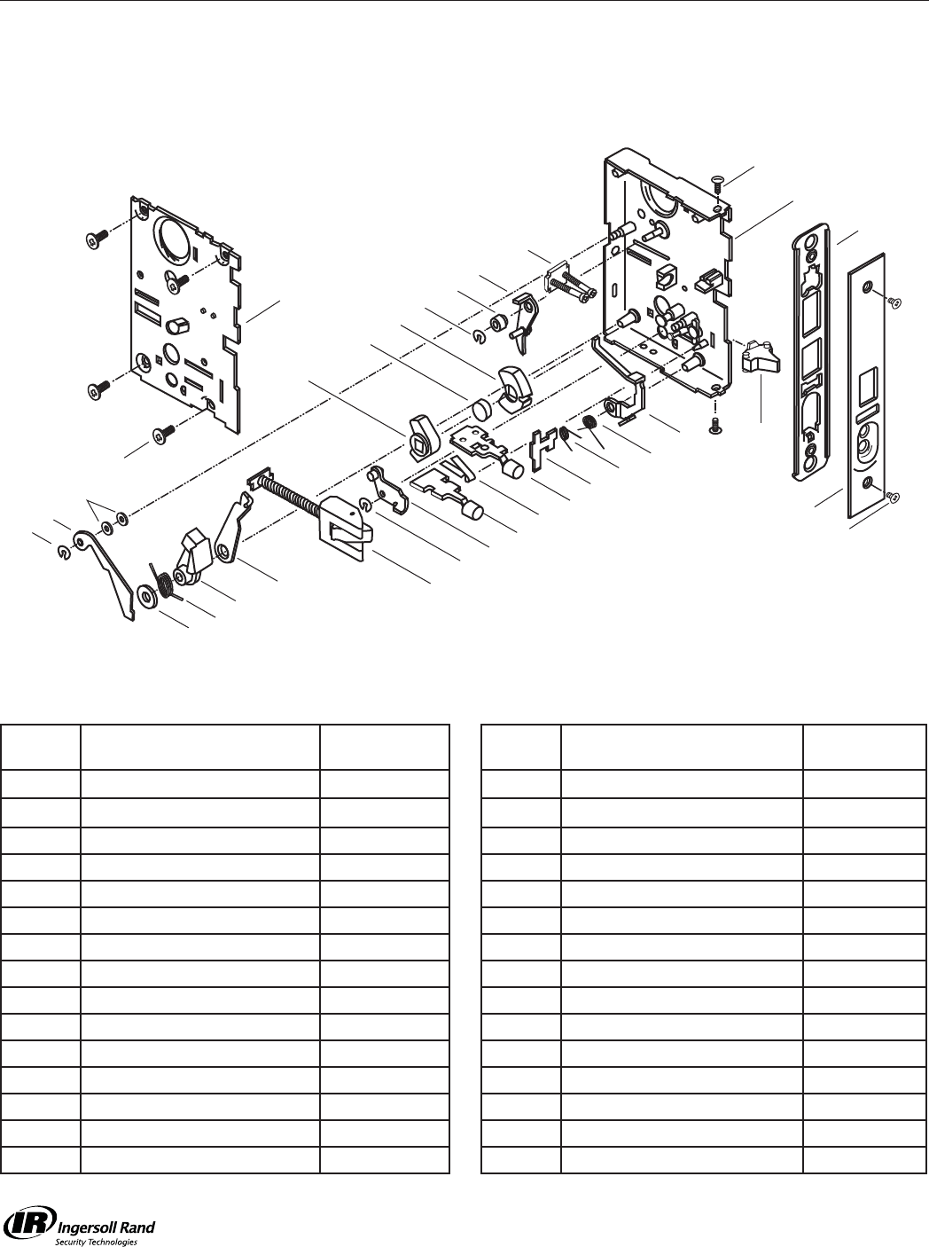
Parts List - A30824-30F * Locking Unit M521
M521 Entry/Offi ce Lock
A30824-000-626
Call Out
Number Description Part Number
Call Out
Number Description Part Number
48 Arm, Blocker Release 020491-000-30 114 Latch Bolt Assy
A20639-004-626
51 Arm, Lower Retract 021185-000-30 115 Lever 020575-000-30
54 Bar, Deadlocking
020579-000-630
121 Retainer Assy. Cyl A21209-000-00
55 Blocker Assy A20957-000-00 128 Ring, Truarc (3) 005347-000-30
56 Blocker, Button 020577-000-30 129 Screw 8-32 x 1/4 (2) K110-020
57 Button Assy, Locking
A20958-000-626
130 Screw 8-32 x 3/8 (4) 002801-006-30
58 Button Assy, Non-Lock
A20915-000-626
131 Screw 8-32 x 3/8 (2) 002932-000-30
63 Case Assy A20587-002-00 132 Sleeve, Lever Post 020659-000-10
77 Coupling 020646-000-30 137 Spacer Hub 020674-000-30
79 Cover Assy A23204-000-00 140 Spacer, Washer (2) 020447-000-10
82 Cylinder Lever Assy A20598-000-00 145 Spring, Detent 021162-000-30
87 Faceplate 020098-01U * 147 Spring, DL 020595-001-60
102 Front Plate 1-1/4” Wide 021349-000-30 152 Spring, Low Blocker 020978-000-60
104 Hub, Locking 020643-000-30 153 Spring, Retract Arm 020666-000-60
105 Hub, Non-Locking 020642-000-30 159 Washer, Flat 002900-000-30
RIGHT HAND SHOWN
87
102
129
128
77
114
55 58
153
51
159
145
56
152
57
147
115 54
63
131
128
104
137
105
128
48
140
82
132
121
130
79
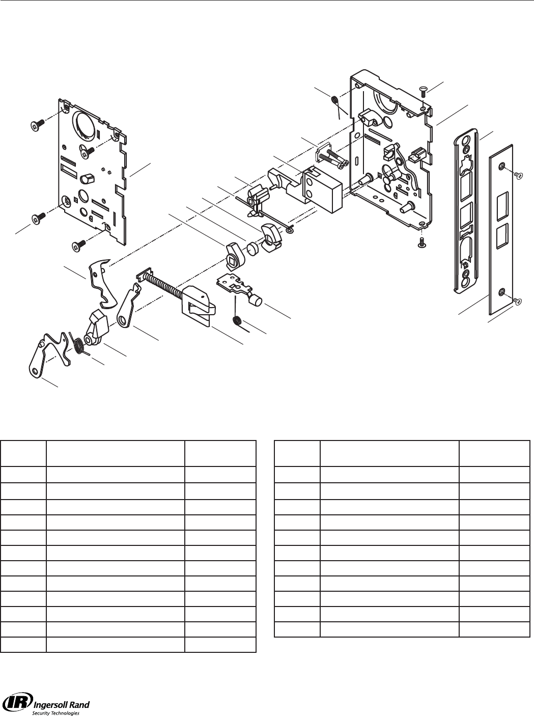
Lock Case Assemblies M-Series Service Manual
23
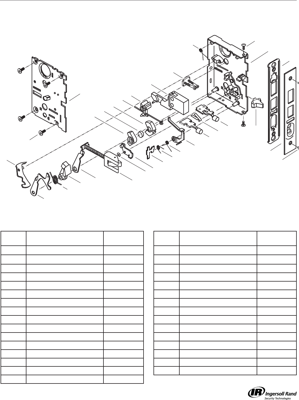
M531 Apartment Lock
A21019-001-626
Parts List - A21308-30F * Locking Unit M361/531
Call Out
Number Description Part Number
Call Out
Number Description Part Number
50 Arm, Lower Retract 020645-000-30 115 Lever 020575-000-30
54 Bar, Deadlocking
020579-000-630
116 Lever & Pin Assy A20602-000-00
55 Blocker Assy A20957-000-00 121 Retainer Assy, Cyl A21209-000-00
56 Blocker, Button 020577-000-30 125 Retract Arm Assy A20601-002-00
57 Button Assy, Locking
A20958-000-626
128 Ring, Truarc 005347-000-30
58 Button Assy, Non-Lock
A20915-000-626
129 Screw 8-32 x 1/4 (2) K110-020
66 Case Assy A20956-001-00 130 Screw 8-32 x 3/8 (4) 002801-006-30
77 Coupling 020646-000-30 131 Screw 8-32 x 3/8 (2) 002932-000-30
79 Cover Assy A23204-000-00 137 Spacer Hub 020674-000-30
85 Deadbolt 1”
030147-002-626
143 Spring, Cyl Lever 021011-000-60
93 Faceplate 020576-01U * 144 Spring, Deadbolt 020641-000-30
102 Front Plate 1-1/4” Wide 021349-000-30 145 Spring, Detent 021162-000-30
104 Hub, Locking 020643-000-30 147 Spring, DL 020595-001-60
105 Hub, Non-Locking 020642-000-30 152 Spring, Low Blocker 020978-000-60
109 Hub, T-Turn 020652-001-30 153 Spring, Retract Arm 020666-000-60
114 Latch Bolt Assy
A20639-004-626
*= Finish or Specify Finish on All
RIGHT HAND SHOWN
129
93
102
131
125
116
50 114
12855
56
137
104
144109
85
121
143
152
147
115
58
145
57 54
77
153
66
105
130
79
Lock Case Assemblies
M-Series Service Manual
24
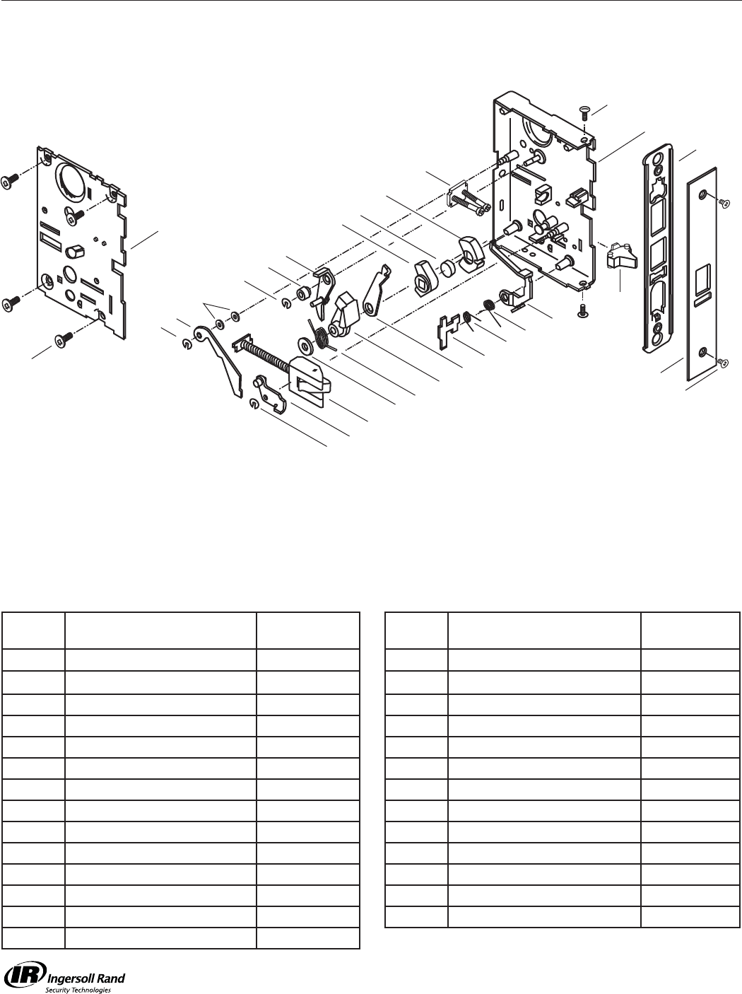
Parts List - A30830-30F * Locking Unit M581
M581 Storeroom/Exit Lock
A30830-000-626
Call Out
Number Description Part Number
Call Out
Number Description Part Number
48 Arm, Blocker Release 020491-000-30 115 Lever 020575-000-30
51 Arm, Lower Retract 021185-000-30 121 Retainer Assy, Cyl A21209-000-00
54 Bar, Deadlocking
020579-000-630
128 Ring, Truarc (3) 005347-000-30
55 Blocker Assy A20957-000-00 129 Screw 8-32 x 1/4 (2) K110-020
56 Blocker, Button 020577-000-30 130 Screw 8-32 x 3/8 (4) 002801-006-30
61 Case Assy A20584-002-00 131 Screw 8-32 x 3/8 (2) 002932-000-30
77 Coupling 020646-000-30 132 Sleeve, Lever Post 020659-000-10
79 Cover Assy A23204-000-00 137 Spacer Hub 020674-000-30
82 Cylinder Lever Assy A20598-000-00 140 Spacer, Washer (2) 020447-000-10
89 Faceplate 020099-01U * 147 Spring, DL 020595-001-60
102 Front Plate 1-1/4” Wide 021349-000-30 152 Spring, Low Blocker 020978-000-60
104 Hub, Locking 020643-000-30 153 Spring, Retract Arm 020666-000-60
105 Hub, Non-Locking 020642-000-30 159 Washer, Flat 002900-000-30
114 Latch Bolt Assy
A20639-004-626
*= Finish or Specify Finish on All
RIGHT HAND SHOWN
89
102
129
61
131
121
104
137
105
77
153
51
159
128 48
140
128
132 82
128
114
56
152
147 115
54
55
130
79
Lock Case Assemblies M-Series Service Manual
25
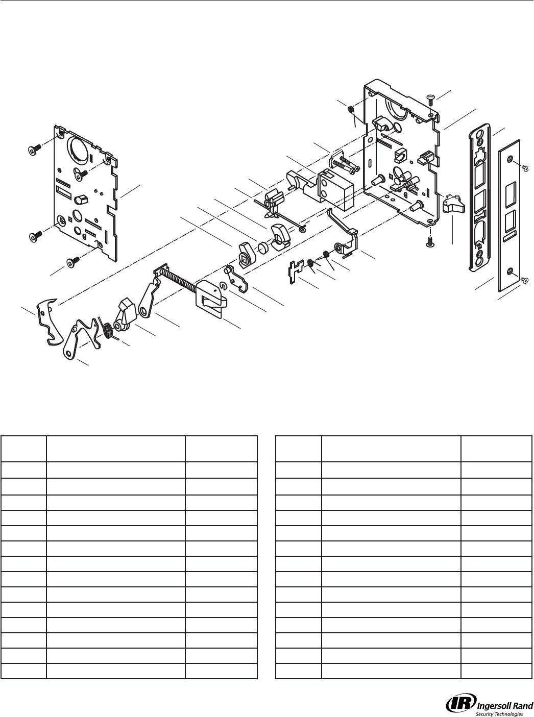
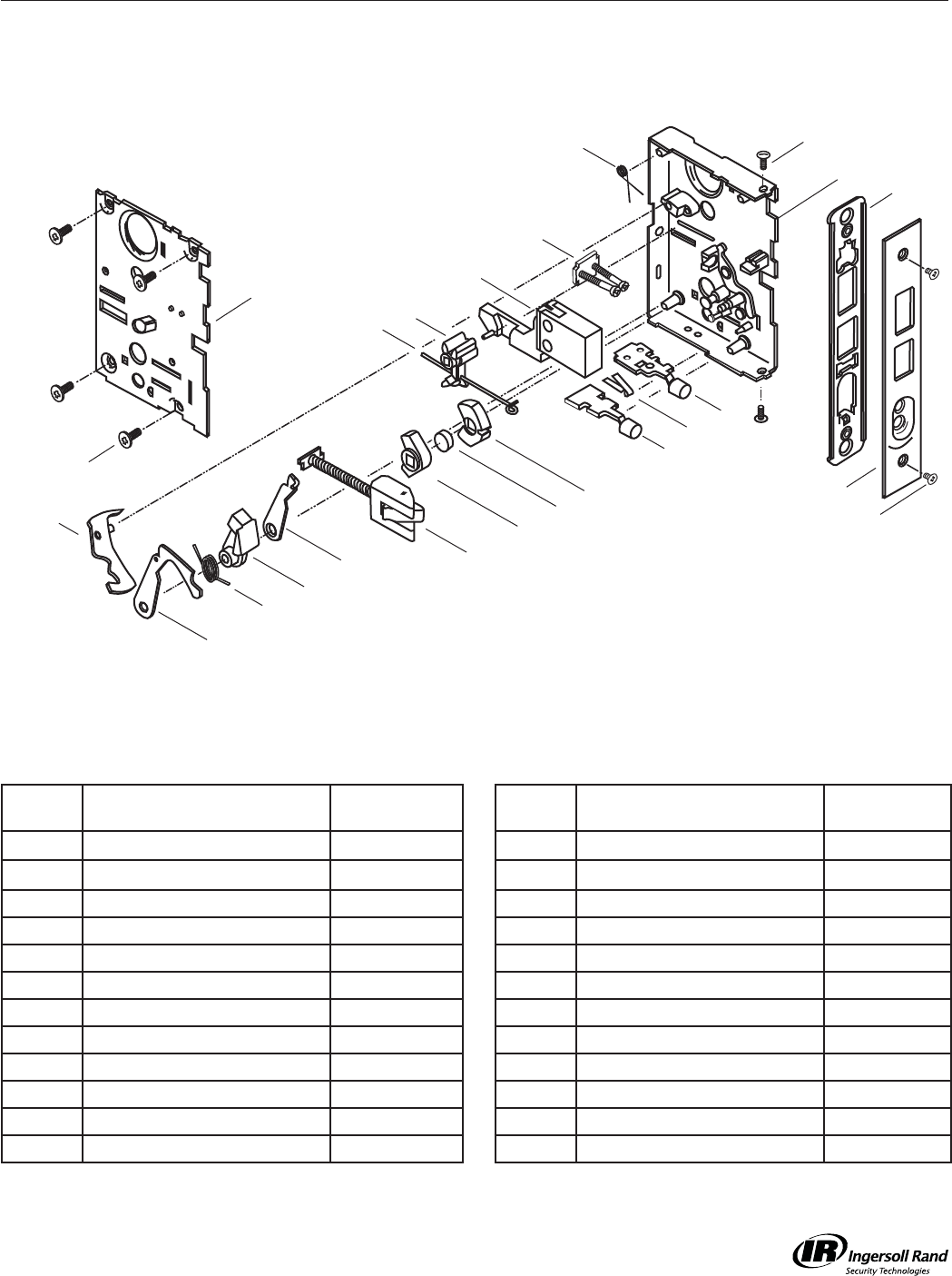
Parts List - A30821-30F * Locking Unit M621
M621 Front Door Lock
A30821-000-626
Call Out
Number Description Part Number
Call Out
Number Description Part Number
50 Arm, Lower Retract 020645-000-30 114 Latch Bolt Assy
A20639-004-626
57 Button Assy, Locking
A20958-000-626
116 Lever & Pin Assy A20602-000-00
58 Button Assy, Non-Lock
A20915-000-626
121 Retainer Assy, Cyl A21209-000-00
66 Case Assy A20956-001-00 125 Retract Arm Assy A20601-003-00
77 Coupling 020646-000-30 129 Screw 8-32 x 1/4 (2) K110-020
79 Cover Assy A23204-000-00 130 Screw 8-32 x 3/8 (4) 002801-006-30
85 Deadbolt 1”
030147-002-626
131 Screw 8-32 x 3/8 (2) 002932-000-30
94 Faceplate 030281-00U * 137 Spacer Hub 020674-000-30
102 Front Plate 1-1/4” Wide 021349-000-30 143 Spring, Cyl Lever 021011-000-60
104 Hub, Locking 020643-000-30 144 Spring, Deadbolt 020641-000-30
105 Hub, Non-Locking 020642-000-30 145 Spring, Detent 021162-000-30
109 Hub, T-Turn 020652-001-30 153 Spring, Retract Arm 020666-000-30
*= Finish or Specify Finish on All
RIGHT HAND SHOWN
94
102
129
66
131
104
137
105
77
153
50
116
144 109
85
114
143
58
145
57
125
121
130
79
Lock Case Assemblies
M-Series Service Manual
26
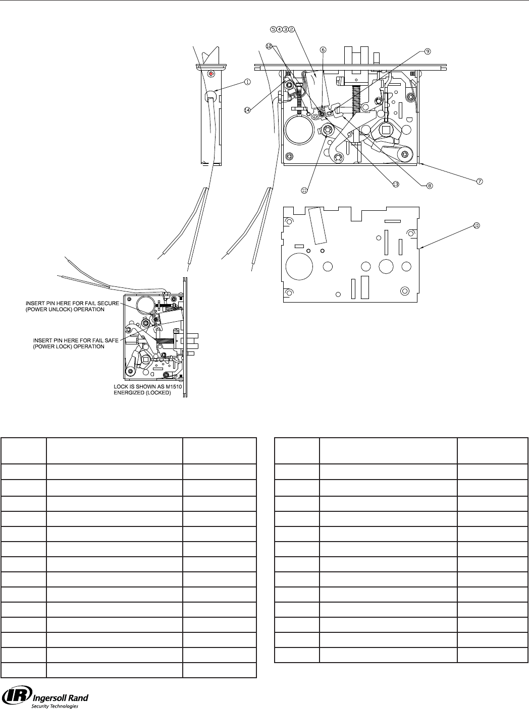
Parts List - Axxxx * Locking Unit M851
See Page 31
M851 Lock
Axxxxx
Call Out
Number Description Part Number
Call Out
Number Description Part Number
1 Heyco Strain Relief 08-06-02
2 24V DC Solenoid Ass’y 315-158-01
3 12V DC Solenoid Ass’y
315-158-02
4 24V AC Solenoid Ass’y 315-158-03
5 12V AC Solenoid Ass’y 315-158-04
6 #8 Flat Washer 89-04-25
7 Case 408-57-01
8 Pivot Link 415-463-01
9 PIN 415-217-01
10 Mortise Lid 422-410-01
11 Spacer - Key Retractor 410-14-01
12 Post 422-386-01
13 Spacer 407-24-01
14 Cable Tie
08-01-02
*= Finish or Specify Finish on All
Lock Case Assemblies M-Series Service Manual
27
*= Finish or Specify Finish on All
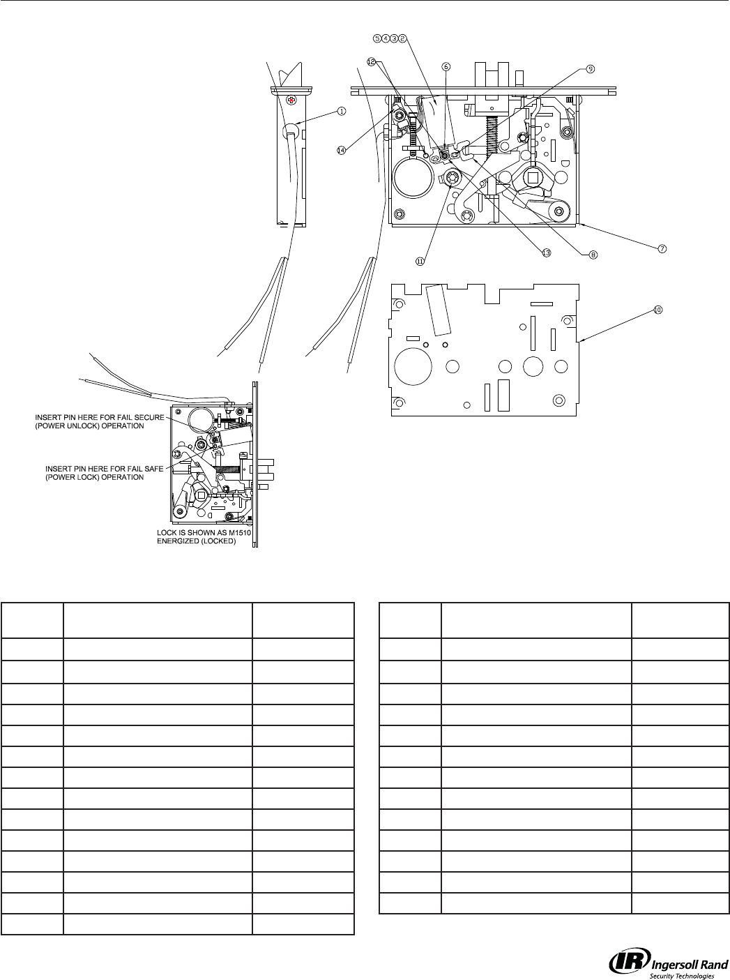
Parts List - Axxxx * Locking Unit M881
See Page 31
M881 Lock
Axxxxx
Call Out
Number Description Part Number
Call Out
Number Description Part Number
1 Heyco Strain Relief 08-06-02
2 24V DC Solenoid Ass’y 315-158-01
3 12V DC Solenoid Ass’y
315-158-02
4 24V AC Solenoid Ass’y 315-158-03
5 12V AC Solenoid Ass’y 315-158-04
6 #8 Flat Washer 89-04-25
7 Case 408-57-01
8 Pivot Link 415-463-01
9 PIN 415-217-01
10 Mortise Lid 422-410-01
11 Spacer - Key Retractor 410-14-01
12 Post 422-386-01
13 Spacer 407-24-01
14 Cable Tie
08-01-02
Lock Case Assemblies
M-Series Service Manual
28
Parts List - A20839-30F * Locking Unit Deadbolt
M911/921/931/941 Deadbolt
A20839-000-626
Call Out
Number Description Part Number
Call Out
Number Description Part Number
65 Case Assy A20591-000-00 109 Hub, T-Turn 020652-001-30
78 Cover 020854-000-30 121 Retainer Assy, Cyl A21209-000-00
84 Deadbolt 1” 030147-000-626 129 Screw 8-32 x 1/4 (2) K110-020
92 Faceplate 020432-000 * 130 Screw 8-32 x 3/8 (4) 002801-006-30
102 Front Plate 1-1/4” Wide 021349-000-30 144 Spring, Deadbolt 020641-000-30
*= Finish or Specify Finish on All
130
78
92
102
129
131
109
84
144
121
65

M-Series Service Manual
29
Mortise Locking Units
FUNCTION
101
161
301
311
321
531
371/541
381/441/561
411
451/641/711
521
431/571
581
621
851
881
911/921/931/941
M12
M18
W/ FACEPLATE
A20800-3xx-*
A30842-3xx*
A20806-3xx-*
A21863-3xx-*
A30539-3xx-*
A21308-3xx-*
A20809-3xx-*
A30812-3xx-*
A30815-3xx-*
A30836-3xx-*
A30824-3xx-*
A20827-3xx-*
A30830-3xx-*
A30821-3xx-*
A38816-xSA-*
A38816-xSE-*
A20839-30F-*
(not handed)
FACEPLATE
020100-000-*
020099-01U-*
020109-000-*
020109-000-*
020100-000-*
020576-01U-*
020109-000-*
020099-01U-*
020099-01U-*
014548-01U-*
020098-01U-*
020109-000-*
020099-001-*
030281-00U-*
020099-01U-*
020099-01U-*
020432-000-*
*Specify fi nish 606, 612, 613, 630
xx = RH - Right Hand
LH - Left Hand
RR - Right Hand Reverse
LR - Left Hand Reverse
xxx = 0RH - Right Hand
0LH - Left Hand
RHR - Right Hand Reverse
LHR - Left Hand Reverse
NOTE: Chassis for M101, M161, M301, M371/541, M411, M551 are Left Hand or Right Hand ONLY
Lock Functions and Accessories

M-Series Service Manual
30
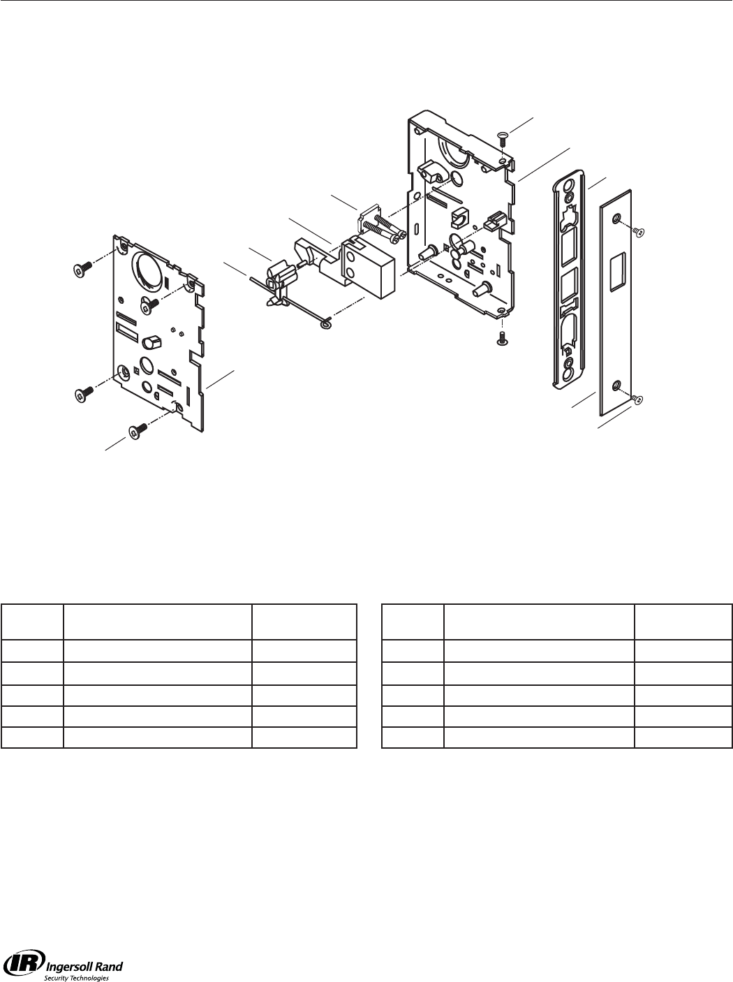
Electrifi ed Mortise Chassis - Maxim W/ 030173-004-* Screws
FUNCTION
M851 Fail Safe 12 VAC/DC
M851 Fail Safe 24 VAC/DC
M881 Fail Secure 12 VAC/DC
M881 Fail Secure 24 VAC/DC
W/ FACEPLATE
A38816-1SA-*
A38816-2SA-*
A38816-1SE-*
A38816-2SE-*
FACEPLATE
020099-01U-*
020099-01U-*
020099-01U-*
020099-01U-*
W/O FACEPLATE
A38812-1SA-626
A38812-2SA-626
A38812-1SE-626
A38812-2SE-626
Made from
A30812-000-626
* Finish 606, 612, 613, 630
Lock Functions and Accessories
M-Series Service Manual
31
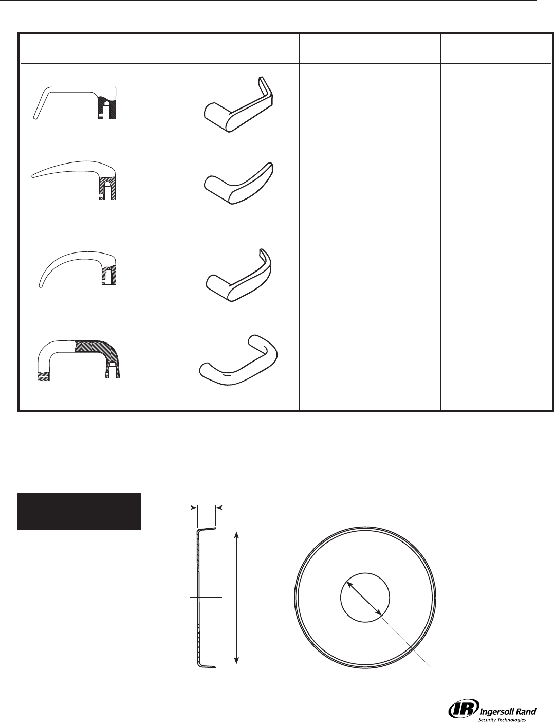
Roses
Lock Functions and Accessories
Gala
030052-000
0.885” dia. hole
2.442” dia.
0.371”
For Knurled Lever identify as
Levers
Outer Inner
Dane 021280-000 A30202-00D
Avalon 030029-000 A30202-00A
Quantum 030140-000 A30202-00Q
Sutro 030526-000 A30202-00S
Inside Outside
M-Series Service Manual
32
Escutcheons
Lock Functions and Accessories
030066-001 030066-003 030066-005 030066-008 030066-013030066-009 030066-011030066-010 030066-012
Lock Case Assemblies
Description
(Part Number)
101/161
301/311/321
361/371/381
411
451
521
531/541
561
571
581
621
631
641
711
771
811/821
851
881
911
921
931
941
Napa Passage
(030066-001) ••
(i)
•
(i)
•
(i)
•
(i)
•
(i)
•
(i)
•
(i)
Napa T-Turn
Prep
(030066-003)
••
(i)
•
(i)
•
(i)
•
(i)
•
(i)
•
(i)
Napa Cyl
(030066-005) •• •
(o)
•
(o)
•
(o)
•
(o)
•
(o)
•
(o)
•
(o)
•
(o)
•
(o)
••
(o)
•
(o)
Napa w/
Indicator Hole
(030066-008)
•
(o)
(030066-009) •
(i)
(030066-010) •
(i)
(030066-011) • •
(o)
••
(o)
(030066-012)
Napa w/cyl/
emergency hole
(030066-013)
•
(o)
(i) = inside (o) = outside
* -002, -004, -006, -007 escutcheons are used on the RW-series retrofi t
M-Series Service Manual
33
Lock Functions and Accessories
Strikes
LH A21316-0xx 020569-000LH A21315-0xx 020568-000 020317-000RH A21316-0xx RH A21315-0xx
Standard Strikes
(Lip Length)
Optional Strikes
(Lip Length)
Strikes Sold Separate
(Lip Length)
Description
020569 (1-1/8”)*
020568 (1-1/8”)*
021317 (1-1/4”)
21315 (1-1/4”)
21316 (1-1/4”)
20318 (1-1/4”)*
20319 (1-1/8”)*
A21315-0xx (1-1/4”)*
A21316-0xx (1-1/4”)*
021317-000 (1-1/4”)
020568-000 (1-1/8”)
020569-000 (1-1/8”)
020318-0xx (1-1/8”)*
020319-0xx (1-1/8”)*
Strike for latchbolt only
M101, 161, 321, 381,
411, 441, 521, 561,
581, 851, 881
•• ••
Strike for deadbolt and
latch
M301, 311, 371, 431,
451, 531, 541, 571,
621, 641, 711
•• ••
Strike for deadbolt only • •
Strike for smoke seal
or tight fi tting doors
latchbolt only
••
Strike for smoke seal or
tight fi tting doors latch
and deadbolt only
••
*Specify hand for all curved lip strikes
M-Series Service Manual
34
Armor Fronts/Faceplates/Sclops
Part Number Description Part Number Description
M431
M451
M631
M641
M711
M301
M311
M371
M541
M571
M521
M911
M921
M931
M941
M381
M411
M441
M561
M581
M851
M881
M531
M101
M321 M621
014548-01U 020109-000
020098-01U 020432-000
020576-01U
020099-01U
030281-00U
020100-000
Finishes: 606, 613, 630
Notes: Screws supplied at no charge when requested.
M-Series Service Manual
35
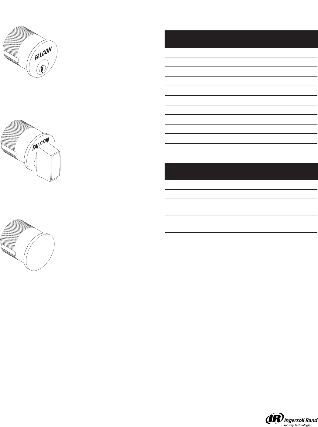
Mortise Cylinders
Mortise, Rim and Cam Lock for Standard Cylinders
Mortise Cylinder
900 Series Cylinders are
furnished with #4 straight
cam and 250 Series with
#1 cloverleaf cam unless
otherwise specifi ed.
See table for product numbers.
See pages 32-33 for optional
cams and 34-35 for collars.
Thumbturn Cylinder
Furnished with #4 straight cam
except 970 Series furnished
with #1 cloverleaf cam unless
otherwise specifi ed.
See table for product numbers.
See pages 32-33 for optional
cams and 34-35 for collars.
Dummy Cylinder
Used to plug hole in door
where lock remains but cylinder
operation is no longer needed.
984 1”
985 1-1/8”
Note: Specify fi nish: 605,
606, 612, 613, 626, 629,
630
Note: Specify fi nish: 605,
606, 612, 613, 626, 629,
630
Note: Specify fi nish: 605,
606, 612, 613, 626, 629,
630
Specify cylinder number, keyway, and fi nish when ordering.
Catalog
Number Length Pins Application
985 1-1/8” 5 or 6 Generic
986 1-1/4” 5 or 6 Generic
987 1-3/8” 6 or 7 Generic
988 1-1/2” 6 or 7 Generic
990 1-3/4” 6 or 7 Generic
992 2” 6 or 7 Generic
250 1-1/8” 6 M451 hotel function
251 1-1/4” 6 M451 hotel function
252 1-3/8” 6 M451 hotel function
253 1-3/8” 7 M451 hotel function
Catalog
Number Length Pins Application
985T 1-1/8” - Generic
986T 1-1/4” - Generic
973 1-1/8” - M911 Classroom
Thumbturn, RH (CCW)
974 1-1/8” - M911 Classroom
thumbturn, LH (CW)
Keyed Mortise Cylinders
Thumbturn Mortise Cylinders
M-Series Service Manual
36
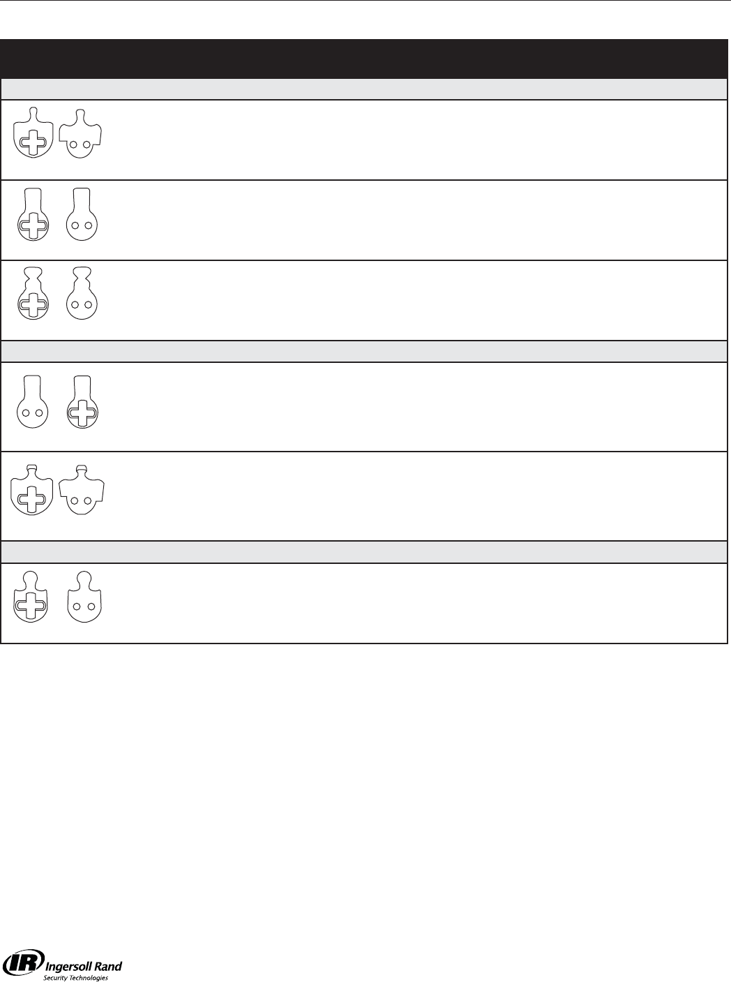
Lock Ref.
Number Part Number For Cylinder
Falcon
Falcon M Series deadbolt functions
1
2
3
10
A09894-001-00
A09894-002-00
A09894-003-00
A12667-007-00
Falcon, Ilco, Lori, Schlage
Arrow, Sargent & Yale
Corbin Russwin
Falcon I/C
Falcon M Series non-deadbolt
functions. Most old black cast iron
locks. C/R ML2255 & ML2242 inside.
4
5
A09897-000-00
A12667-003-00
Conventional I/C
Most Exit Devices
Falcon M381 outside 14
15
A20065-00-00
A20278-000-00
Conventional
I/C
Monarch
Monarch Dogging cylinder.
Install cam upside down.
24
5
A09897-024-00
A12667-003-00
Conventional
I/C
Monarch Delta trim for 17C concealed
vertical rod
21
22
23
20
A09894-021-00
A09894-022-00
A09894-023-00
A12667-020-00
Falcon, Ilco, Lori, Schlage
Arrow, Sargent & Yale
Corbin Russwin
I/C
Schlage
Schlage L Series 13
12
A09888-000-00
A12667-008-00
Conventional
I/C
Mortise Cylinders
Cams
Each part number indicates a package of 10 cams.
1, 2, 3
4
14
5
21, 22, 23
13
10
5
15
24
20
12
M-Series Service Manual
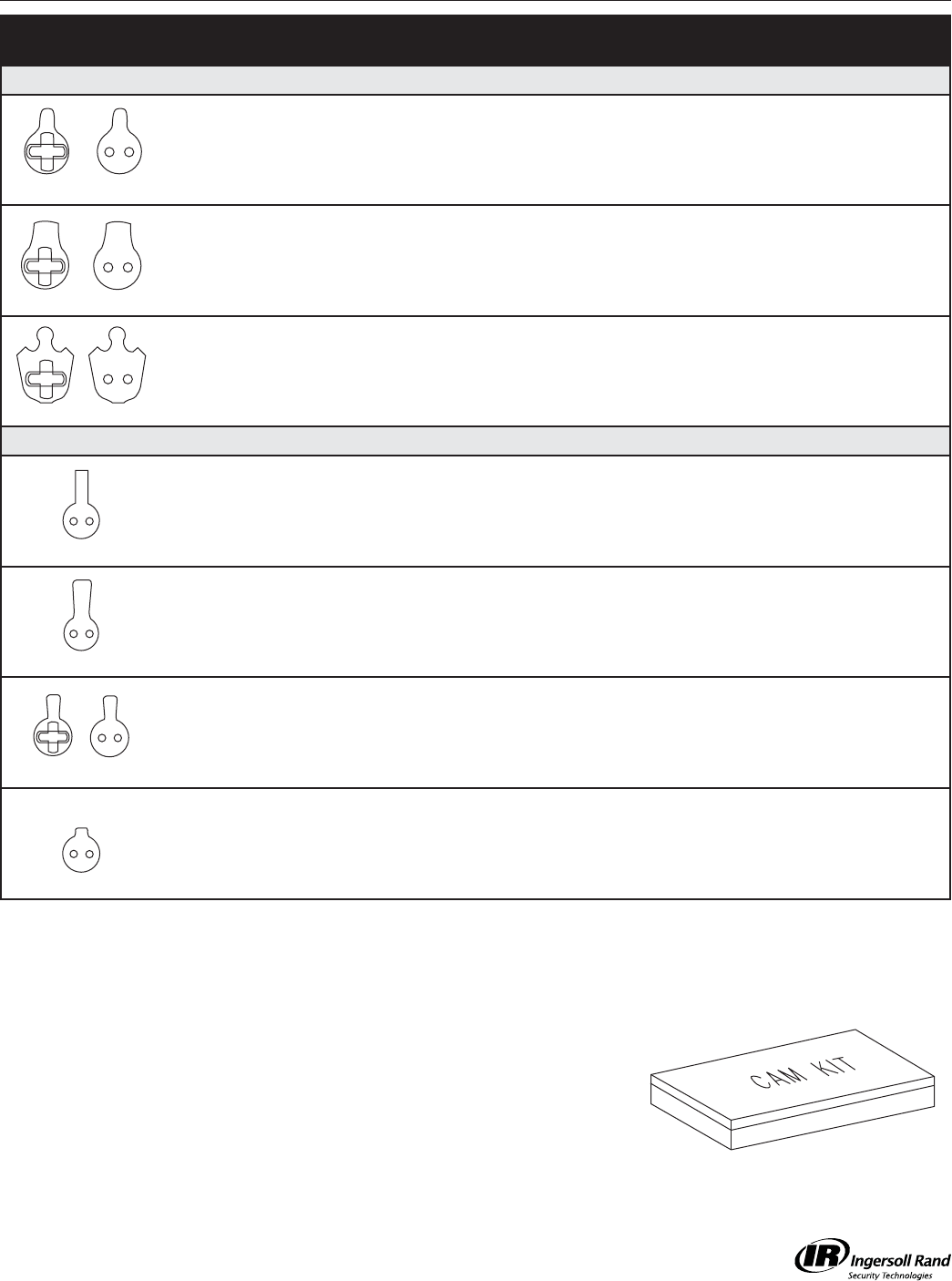
37
Lock Ref.
Number Part Number For Cylinder
Other Manufacturers
Adams Rite MS, 4500 and 4700
Series
6
8
A09899-000-00
A12667-001-00*
Conventional
I/C
Adams Rite 4070 deadlock 16
9
A09898-000-00
A12667-002-00
Conventional
I/C
Arrow, Corbin Russwin ML2200
except ML2255 and ML2242
-
11
A20069-000-00
A12667-001-00
Conventional
I/C
Other Manufacturers
Corbin Russwin DL4000 Series 27 A12667-013-00 I/C
Corbin Russwin master ring black cast
iron locks only. Requires brushing
A09890-000-00
25 A12667-006-00 Conventional I/C
Most exit devices
Sargent & Yale 26
7
A08867-000-00
A12667-000-00
Conventional
I/C
Sargent 7737 - A12667-03A-00* I/C
Mortise Cylinders
Cam Assortment Kits
Each part number indicates a package of 10 cams.
1396 Standard Cylinders
Contains ten each #1, 4, and 13; fi fteen #6 and fi ve each #2, 3
and 14 cams, plus 50 cam screws and a plug follower.
1397 I/C Mortise Cylinders
Contains ten each #5, 7, 10, 11 and 12, twenty #8 and fi ve #15
cams, a supply of throw member pins and plates, and one #1402
staking puncyh,.
1, 2, 3
4
14
13
10
5
15
24
20
12
M-Series Service Manual
38
Mortise Cylinders
Cylinder Collars
Standard Collars for Cylinders Ordered Separately
Escutcheon Trim Rin
Sectional Trim Rin
Length Cylinder Non-AR Cams AR Cam
1” 984D A08794-000 -
1-1/8” 250, 965, 966, 973, 974, 985 Series A08794-000 008876-002
1-1/4” 251, 986 Series A08794-001 008876-003
1-3/8” 252, 253, 987, C987, C997 A08794-002 008876-004
Longer C260 Series, (C)988, (C)990, (C)992 A08794-000 008876-000
Door
Thickness Function 985
1-1/8”
986
1-1/4”
(C)987
1-3/8”
(C)988
1-1/2”
1-1/2” Single cylinder - A08790-000 A08790-001 A08790-002
1-1/2” Double cylinder A08790-000 - - -
1-3/4” Single cylinder - - A08790-000 A08790-001
1-3/4” Double cylinder - A08790-000 A08790-001 A08790-002
2” Single cylinder - - A08790-000 A08790-001
2” Double cylinder - - A08790-000 A08790-001
2-1/4” Single cylinder - - - A08790-000
2-1/4” Double cylinder ----
2-1/2” Single cylinder ----
2-1/2” Double cylinder ----
Door
Thickness Function 985
1-1/8”
986
1-1/4”
(C)987
1-3/8”
(C)988
1-1/2”
1-1/2” Single cylinder A08794-001 A08794-002 - -
1-1/2” Double cylinder A08794-002 A08794-003 - -
1-3/4” Single cylinder A08794-000 A08794-001 - -
1-3/4” Double cylinder A08794-001 A08794-002 A08794-002 -
2” Single cylinder - A08794-000 A08794-001 A08794-002
2” Double cylinder A08794-000 A08794-001 A08794-002 A08794-003
2-1/4” Single cylinder - - A08794-000 A08794-001
2-1/4” Double cylinder - A08794-000 A08794-001 A08794-002
2-1/2” Single cylinder - - - A08794-000
2-1/2” Double cylinder - - A08794-000 A08794-001
Specify part number and fi nish when ordering.
(e.g. A08790-000-626)
M-Series Service Manual
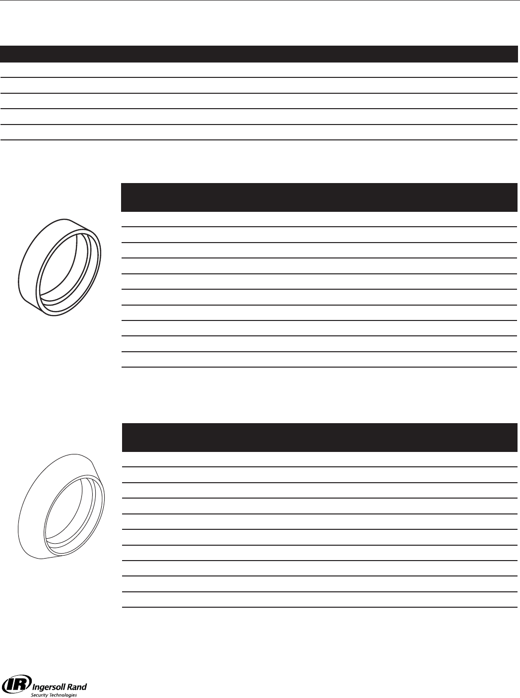
39
Trim Rings & Collars
Mortise Cylinders
Specify part number and fi nish when ordering.
(e.g. A08790-000-626)
Dim. A Dim. B Part No.
3/32” 9/32” A08790-000
7/32” 13/32” A08790-001
11/32” 17/32” A08790-002
15/32” 21/32” A08790-003
43/64” 55/64” A08790-004
3/32” 9/32” A08794-000
7/32” 13/32” A08794-001
11/32” 17/32” A08794-002
15/32” 21/32” A08794-003
1/8” - 008876-000
3/16” - 008876-005
1/4” - 008876-001
3/8” - 008876-002
1/2” - 008876-003
5/8” - 008876-004
A
A
A
B
BWave washer included.
To order separately,
specify 008789-001-60.
008862-000
For all rim cylinders and cam locks.
Note: Specify fi nishes: 605, 606, 612, 613, 625, 626
M-Series Service Manual
40
Instructions
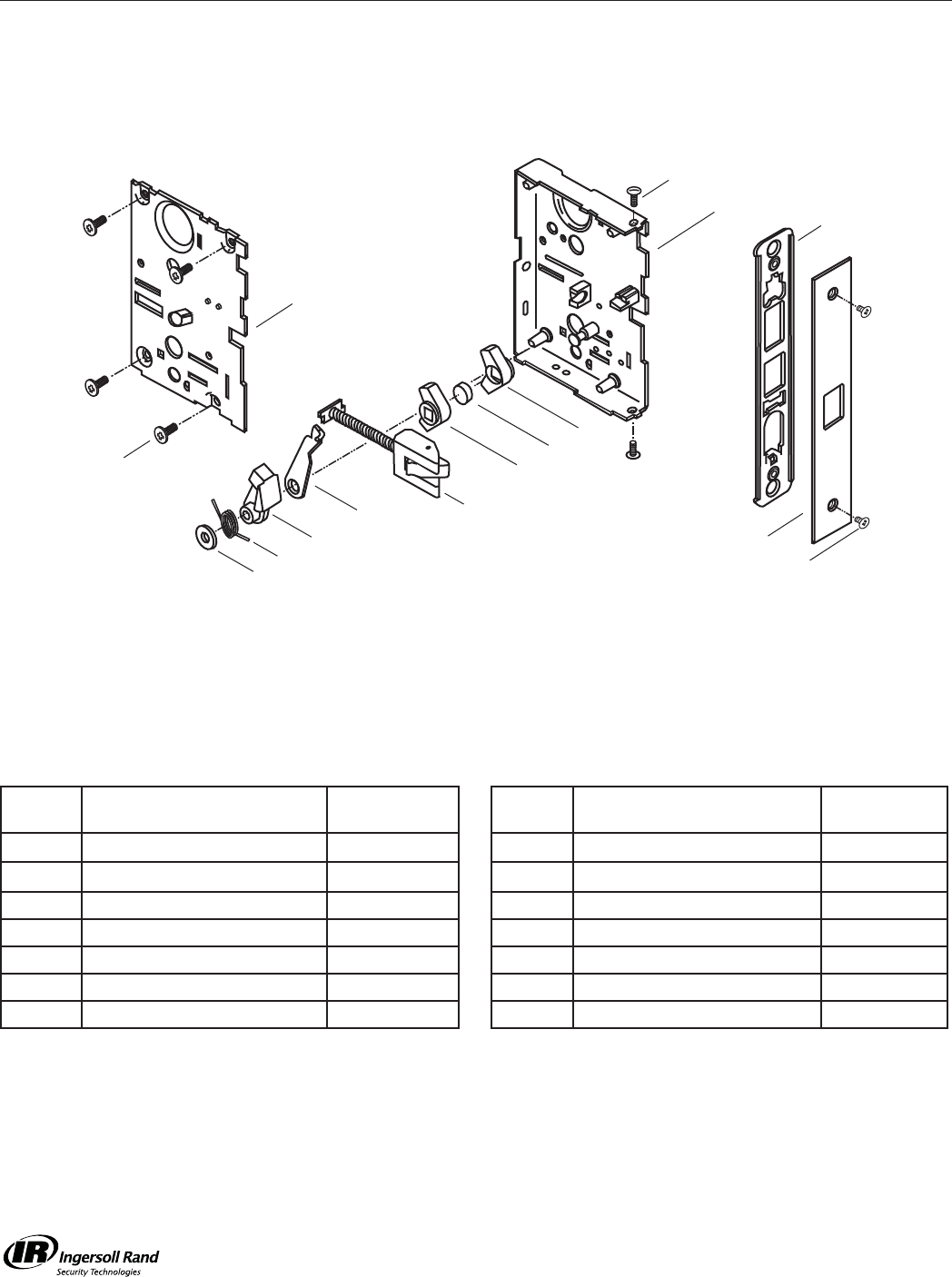
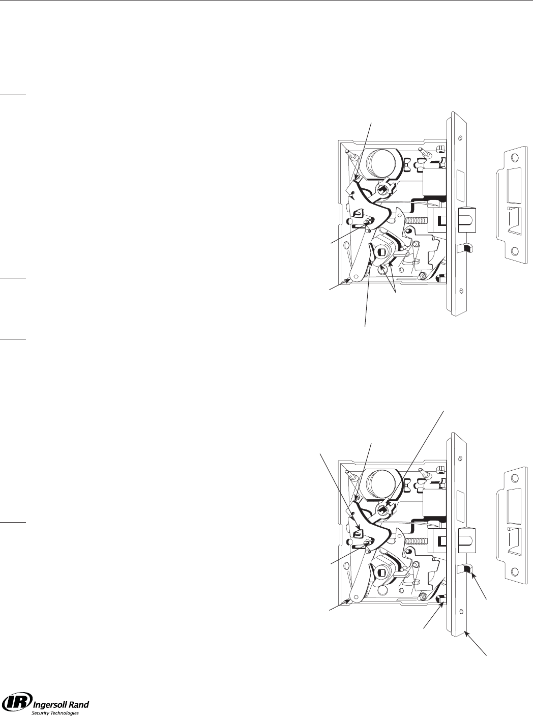
Reversing Hand of Falcon M-Series Mortise Locks
If it is necessary to reverse the hand of a Falcon M-Series
Mortise lock, it is quickly and easily accomplished by the
following steps.
Note:
If the lock has a deadbolt, it must be in the retracted position
when reversing hand.
1. REMOVE COVER
Remove the 4 Cover fastening screws and slowly lift off cover
from case.
2. REVERSE LATCH BOLT ASSEMBLY
A. Lift out Cylinder Retract Lever, if included.
B. Lift out Upper Retract Arm, if included.
C. Compress Latch Bolt Spring toward Faceplate to clear Latch
Bolt Guide seat. Lift out and invert Latch Bolt Assembly. Place
Latch Bolt Spring into Latch Bolt Guide seat.
Note:
Lower Retract Arm must be between Latch Bolt Foot & Latch
Bolt Guide.
3. REVERSE KNOB HUBS
Note:
Knob hub reversing is required only on locks that contain two
differently shaped hubs.
A. To reverse, pull Coupling toward rear of case.
B. Lift out both Hubs together, invert as an assembly and
replace.
C. Ease coupling back into hubs.
4. REASSEMBLE RETRACT ARM AND LEVER
A. Replace Upper Retract Arm so that arm fi ts into space
between Latch Bolt Foot and Coupling.
B. Replace Cylinder Retract Lever so that it straddles the Dead
Bolt Pin.
C. Replace Cover guiding “T” Turn Hub into cover hole. Depress
Latch Bolt to clear Foot.
Note:
A Phillips head screwdriver inserted through cover into “T” Turn
Hub will retain hub and Cylinder Retract Lever in proper location
while replacing cover.
D. Replace Cover fastening screws.
5. ADJUST BEVEL
Set Bevel of lock front to match door Bevel and securely tighten
screws.
6. STRIKE
Replace Strike with Proper Hand condition if necessary.
Cylinder
Retract Lever
Cylinder
Retract Lever
“T” Turn Hub
Foot
Foot
Deadbolt
Pin
Coupling
Lock Front
Screw
Lock Front
Deadlocking
Bolt
Knob Hubs
Upper
Retract Arm
Upper
Retract Arm
M-Series Service Manual
41
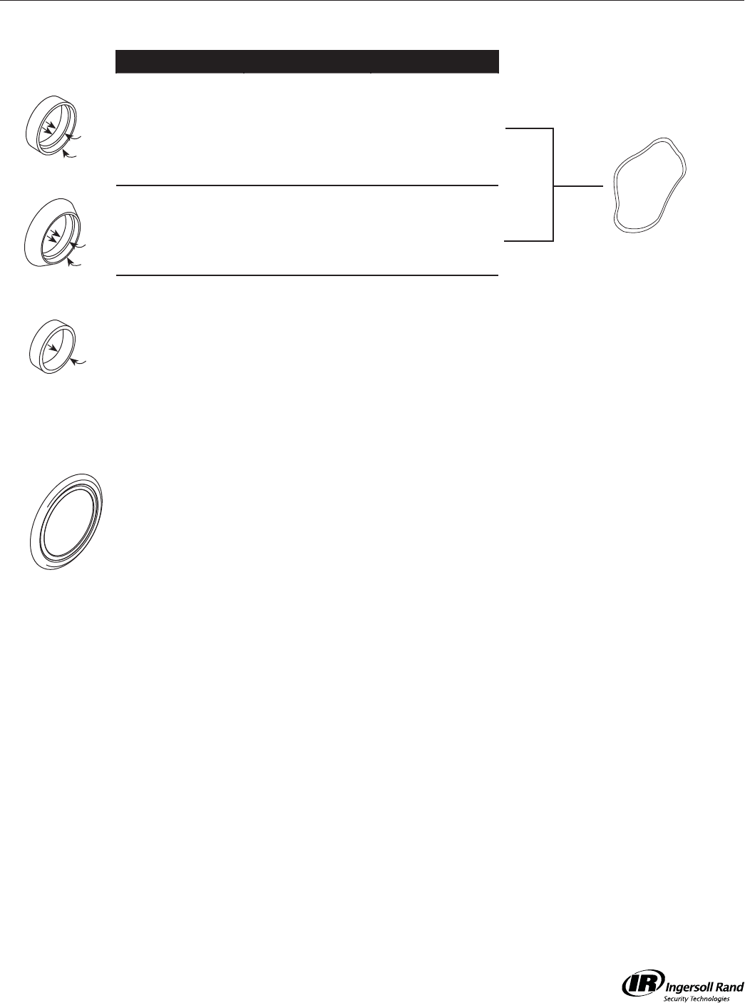
Instructions
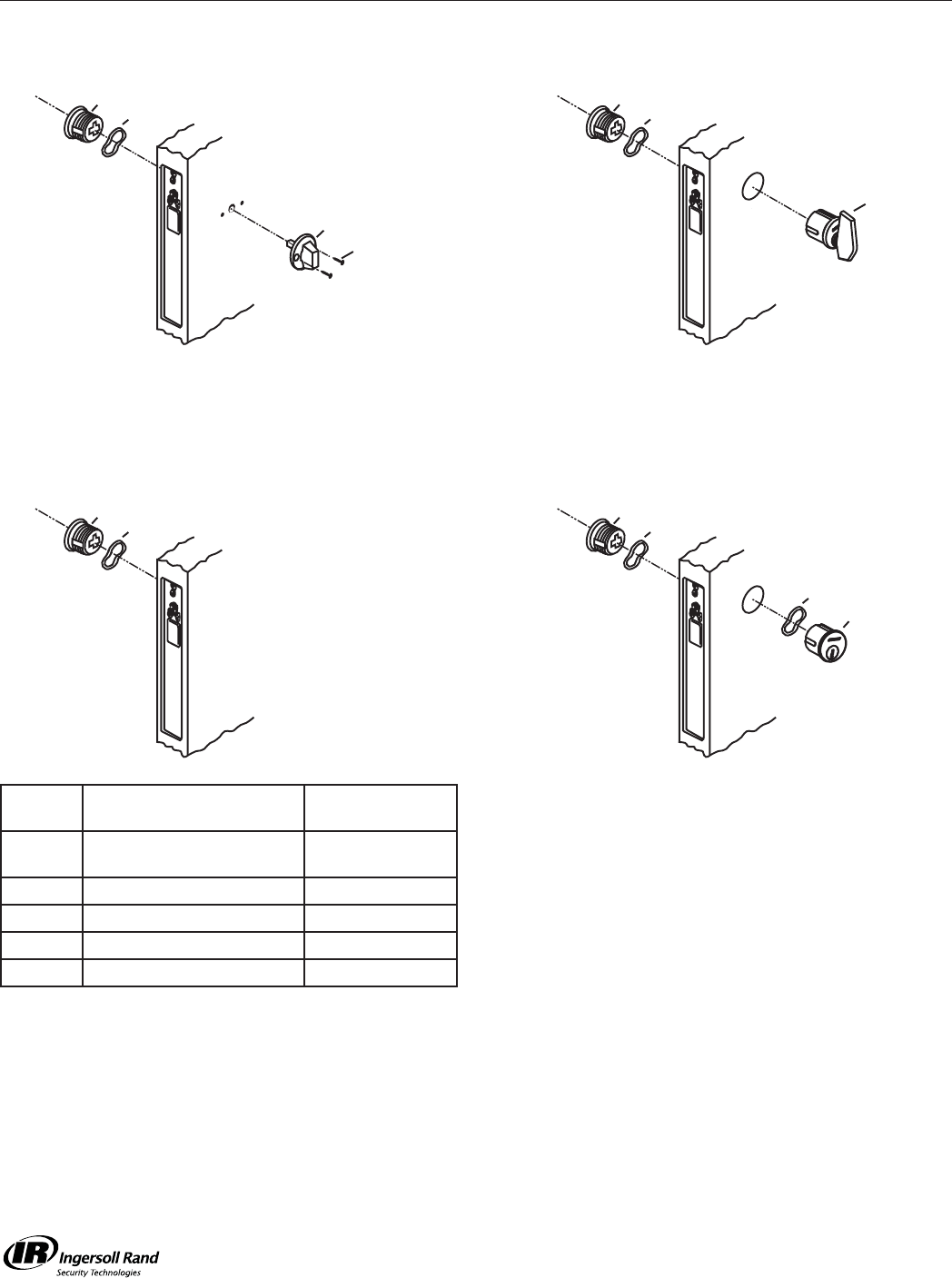
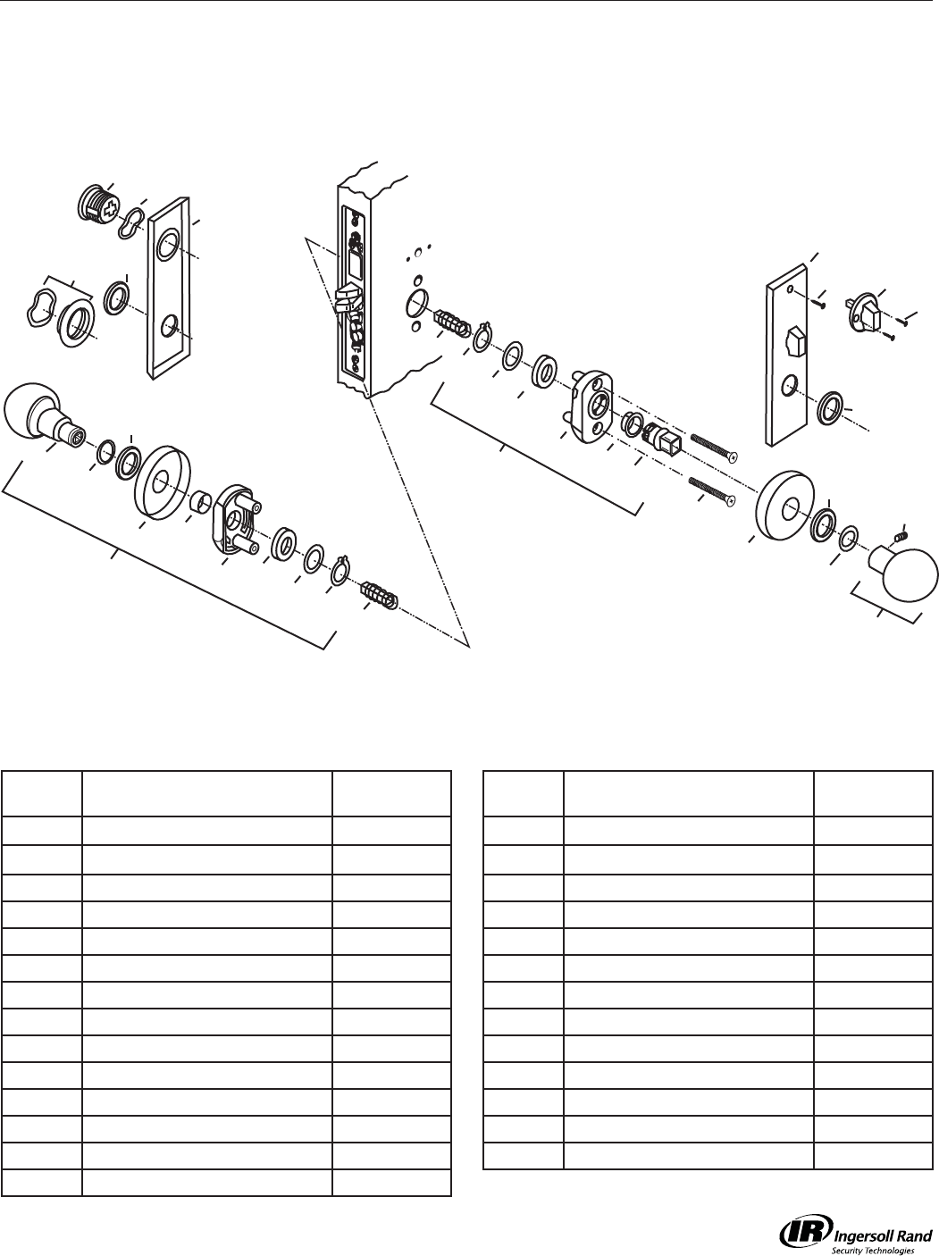
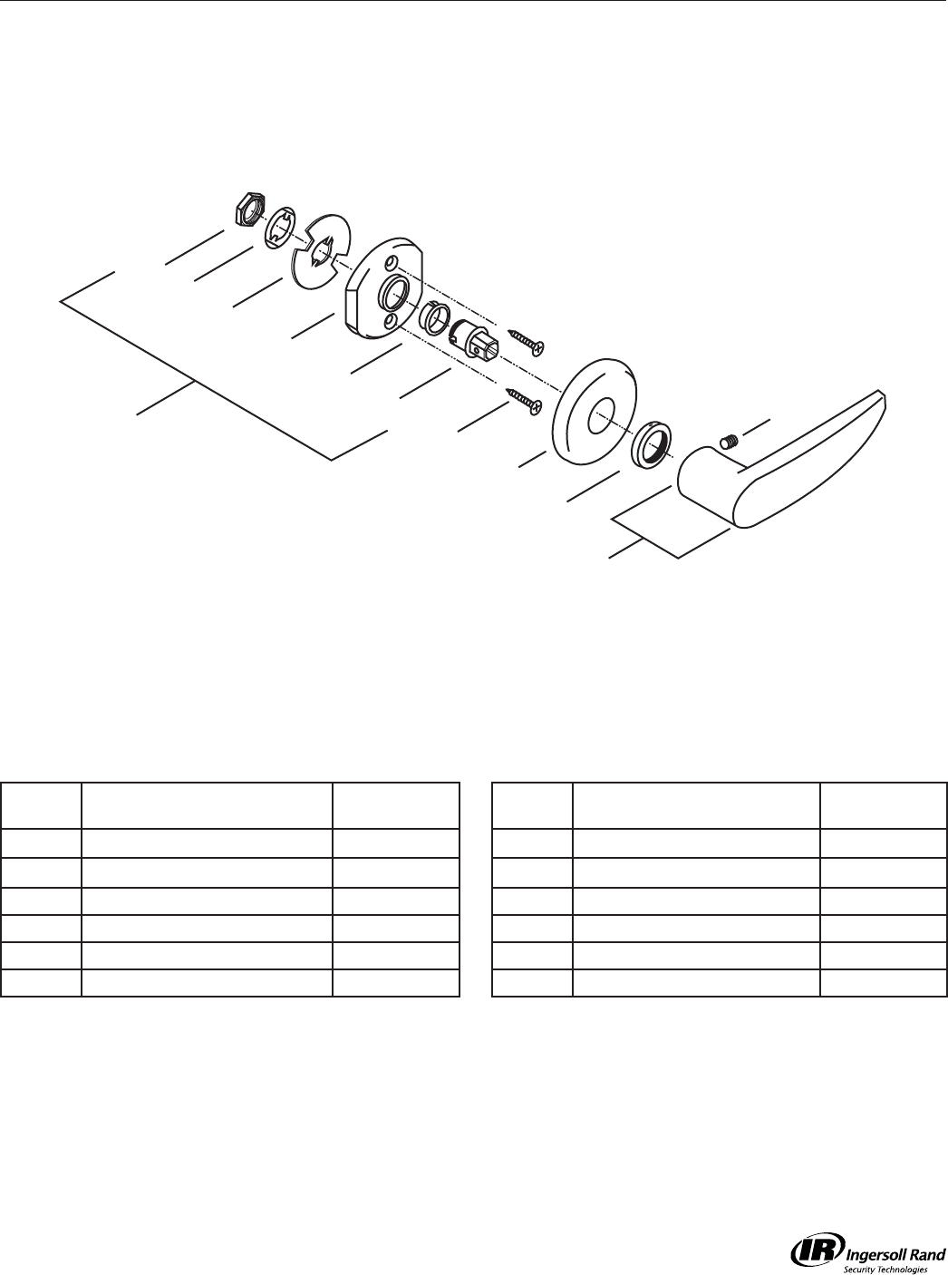
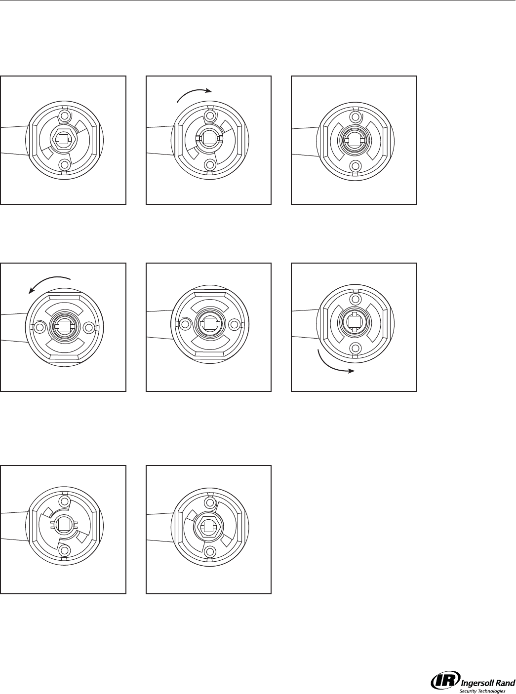
Re-Handing Instructions for Falcon M-Series Lock Trim
L
R
R
L
R
L
R
R
L
R
L
R
L
R
L
R
L
R
L
R
L
R
L
R
L
R
L
L
R
L
R
L
L
R
L
R
1
4
7
2
5
8
3
6
Example shown is right hand being changed to left hand. Reverse sequence to
change from left to right hand.
Note: Inside trim is always opposite the outside trim.
Holding lever as shown,
bend tab of lockwasher back
fl at. Remove nut.
Holding lever securely, rotate
rose assembly clockwise
slightly, and remove plate
and lockwasher.
Using caution, allow rose
assembly to rotate counter-
clockwise to relieve spring
tension.
Reinstall plate with “L” side
up and in line with “L” on
rose assembly.
Remove spring and reinstall
with spring hook on opposite
side of post.
Reinstall lockwasher and nut.
Tighten nut and then back off
slightly until rose assembly
rotates freely under plate.
Bend up two tabs of
lockwasher against nut.
Holding lever securely, rotate
rose assembly counter-
clockwise slightly past 90°.
M-Series Service Manual
42
Instructions
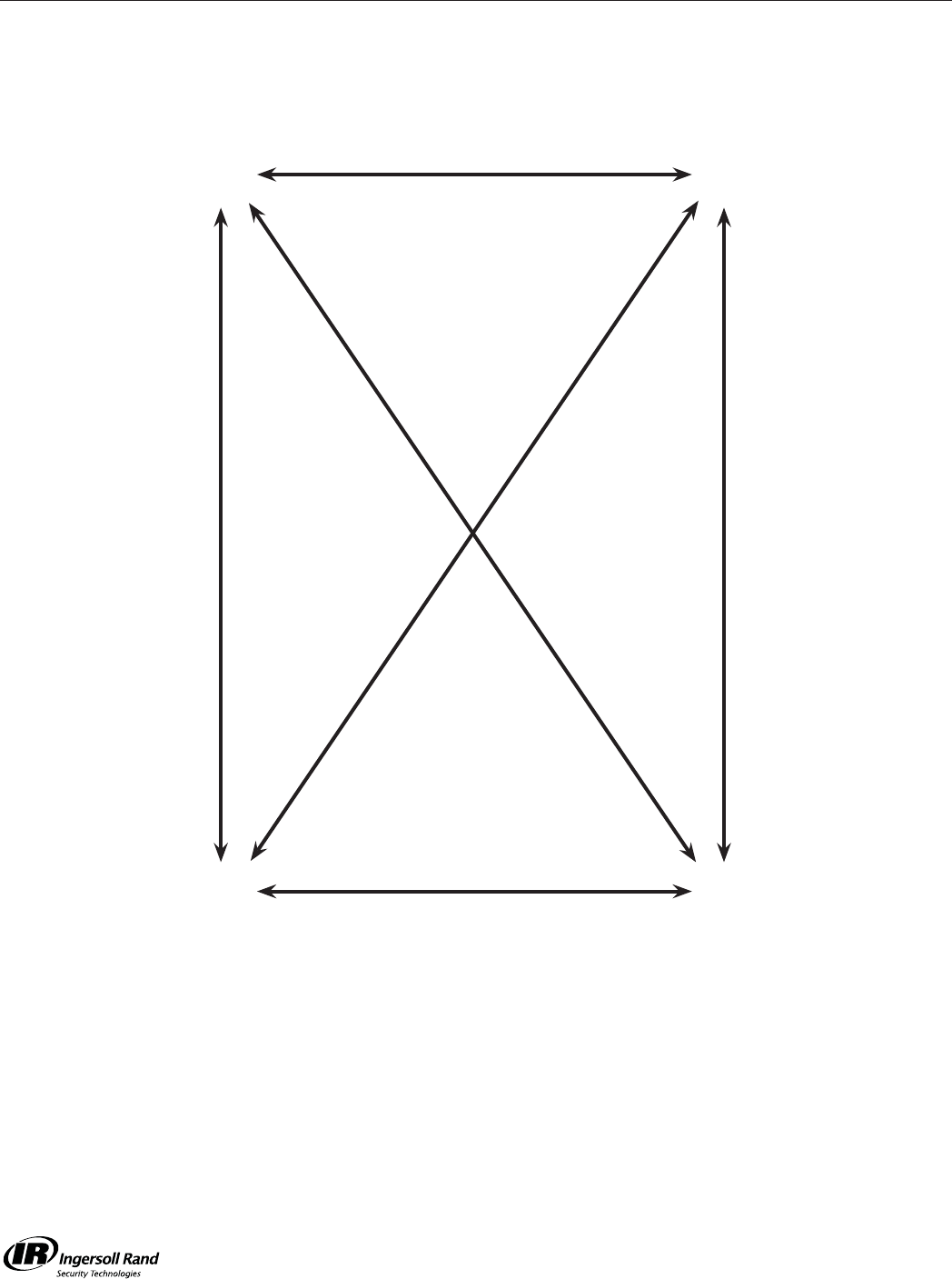
Falcon Mortise Lock Re-Handing Guide
LH
LHR
RH
RHR
Reverse hubs, latchbolt, and Trim
Reverse hubs, latchbolt, and Trim
Reverse Latchbolt only
Reverse Hubs and Trim
Reverse Hubs and Trim
Reverse Latchbolt only

M-Series Service Manual
43

M-Series Service Manual
44

www.falcon.ingersollrand.com
© 2009 Ingersoll Rand Company FA-5733 Rev. 8/09 Printed in U.S.A.
