Fanstel Taipei BH676CP Bluetooth 4.1 Module User Manual BH676CP Manual 1050413
Fanstel Corporation, Taipei Bluetooth 4.1 Module BH676CP Manual 1050413
UserManual.wiki
>
Fanstel Taipei
>
BH676CP User Manual
User manual
Navigation menu
Upload a User Manual
Namespaces
Wiki Guide
HTML
PDF
Info
Views
User Manual
Discussion / Help
Navigation
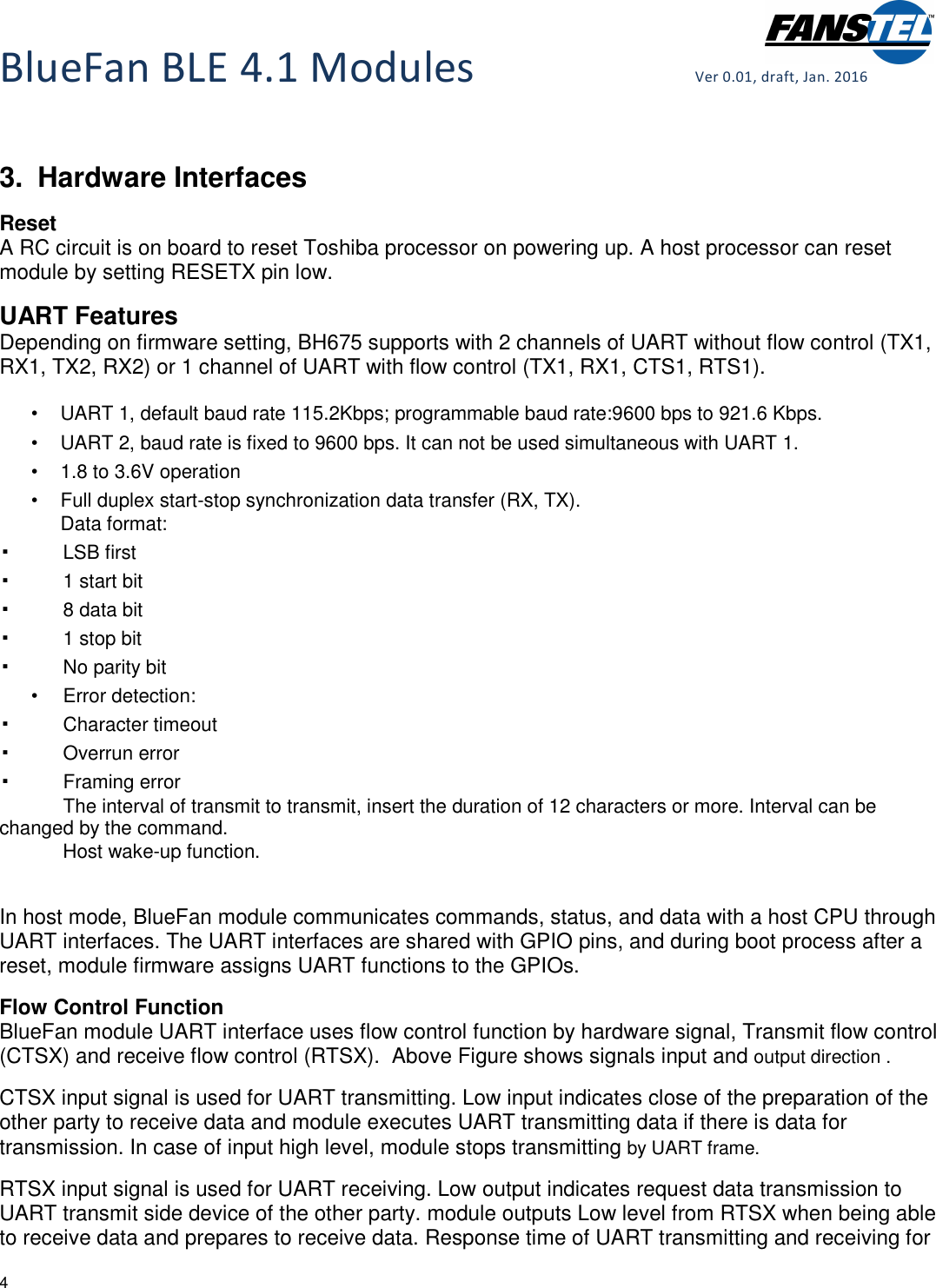
![BlueFan BLE 4.1 Modules Ver 0.01, draft, Jan. 2016 5 flow control signal depends on baud rate and internal process status of frame. It is from 1 frame to 4 frames. Response time of UART transmitting and receiving for flow control signal depends on baud rate and internal process status of frame. It is from 1 frame to 4 frame. UART Baud Rate Setting Module UART interface has a programmable baud rate setting function. The UART baud rate can be set according to the following equation. The baud rate generating clock frequency is set to 26 MHz. The over-sampling number is set to an integer that range from 1 to 65535. UART Baud Rate = Baud rate generating clock frequency/(Over sampling number x dividing ratio) The following table shows examples of UART 1 baud rate setting. The maximum actual baud rate is 921,600 bps. The baud rate for UART 2 is fixed at 9600 bps. Target baud rate[bps] Actual baud rate[bps] Baud rate generating clock(MHz) Over-sampling number Dividing ratio (%) 9,600 9,587 12 226 -0.135 14,400 14,396 14 129 -0.025 19,200 19,174 12 113 -0.135 28,800 28,857 17 53 0.197 38,400 38,462 13 52 0.16 57,600 57,778 15 30 0.309 76,800 76,923 13 26 0.16 115,200 11,556 15 15 0.309 153,600 153,846 13 13 0.16 230,400 232,143 16 7 0.756 307,200 305,882 17 5 -0.429 460,800 464,286 14 4 0.756 921,600 928,571 14 2 0.756 Error Detect Function Module UART interface has 3 kinds of error functions. • Receiver timeout error • Receiver over run error](https://usermanual.wiki/Fanstel-Taipei/BH676CP/User-Guide-2975296-Page-5.png)