Fanstel Taipei BH676CP Bluetooth 4.1 Module User Manual BH676CP Manual 1050413
Fanstel Corporation, Taipei Bluetooth 4.1 Module BH676CP Manual 1050413
User manual
BlueFan BLE 4.1 Modules
Ver 0.01, draft, Jan. 2016
1
Features
Standalone or used with a host MCU by UART interface/HCI Commands
Upgradable to BLE 4.2 with 3 mA peak current consumption.
Castellated pins, easier prototyping, easier production
Toshiba SOC, built-in ARM7TDMI-S processor
▪ 256KB mask-ROM for Bluetooth stacks
▪ 224KB RAM
▪ 256KB flash, for Bluetooth profiles, user data and applications
▪ Supports patch program loader function
Bluetooth RF analog core, baseband digital core and integrated antenna
Transmitter power 0 dBm; Receiver sensitivity: -91 dBm.
Bluetooth Low Energy (BLE) V4.1 GATT profile with OTA (Over The Air)
support.
Up to15 General Purpose IOs to be configured by firmware:
▪ SPI interface, I
2
C interface
▪ UART interface, 9600bps to 921.6 Kbps
▪ Up to 2 wake up interfaces
▪ Up to 6 ADC channels (1 for internal monitoring of VDD).
▪ Up to 3 PWM channels
On board 26 MHz main clock
Operation voltage: 2.0V-3.6V
Peak current consumption, 6 mA; deep sleep mode <0.1uA
Operation Temperature: -40
o
C to +85
o
C
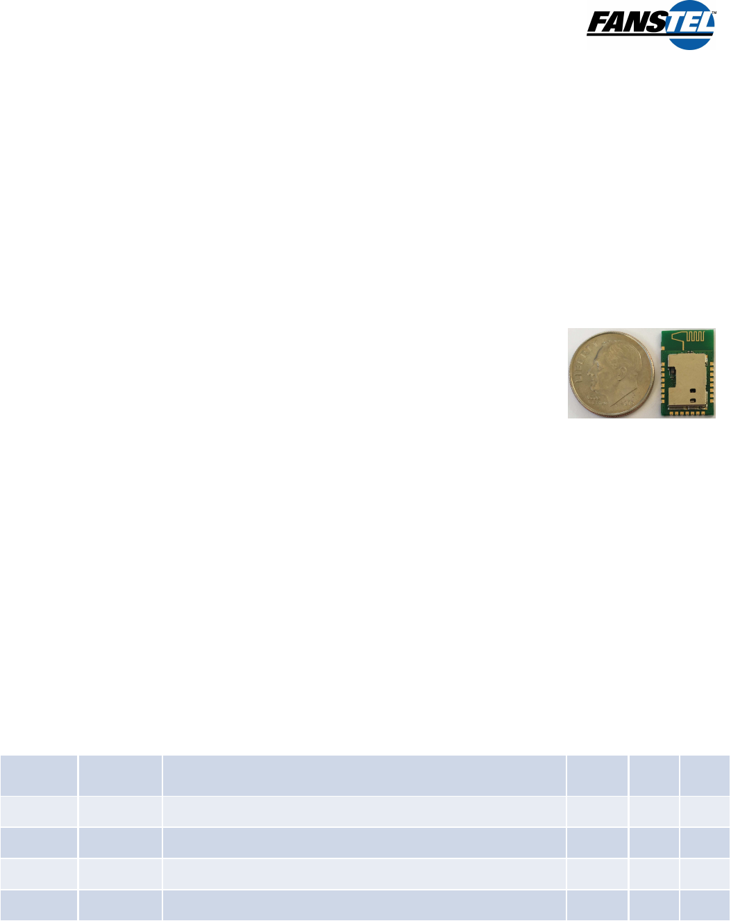
Dimension: 16.7x11.1mm (chip antenna) or 17.7x11.1mm (PCB antenna), CAS(CAStellated): 24 pins.
Integrated shield to resist EMI
Stock modules with FCC approval. Manufacturer pays for other approvals on MOQ.
Applications:
Wearable
Access Points
Industrial Control
Medical
Scanners
iOS and Android devices
Wireless sensors
Cable replacement
Instrumentation
Automobile
Sports
Proximity
Ordering Information:
Module Processor Description Ant. SLP
CLK Stock
BH676CP
TC35676 BLE 4.1 Standalone PCB no yes
BS676CP TC35676 BLE 4.1 Standalone PCB yes no
BH676CC
TC35676 BLE 4.1 Standalone chip no no
BS676CC
TC35676 BLE 4.1 Standalone chip yes no

BlueFan BLE 4.1 Modules
Ver 0.01, draft, Jan. 2016
2
1. Introduction
Host Control Interface Mode
BlueFan modules are Bluetooth Smart module using Toshiba SoC. Toshiba SoC provides
Bluetooth
TM
HCI (Host Control Interface) function specified in Bluetooth
TM
Core Specifications. The
HCI function allows BlueFan to be connected to an external host processor for Bluetooth applications.
Bluetooth stacks and GATT 4.1 profiles are embedded with OTA support.
Standalone Mode
All BlueFan modules work in standalone alone mode without a host processor. In addition to masked
ROM, flash ROM, and RAM for Bluetooth stacks, 128KB of flash ROM and 64KB of RAM are
available for user programs and data.
2. Product Features
BS676CC, Chip antenna
It operates in standalone mode or with a host processor. A 26MHz main clock crystal is on board.
The 32.768 KHz sleep clock is integrated for low power consumption.. This module can be wake up
by an external signal. A chip antenna is integrated. Connection to an external antenna is available.
Co-existence connection with WiFi is provided.
Standalone or used with a host by UART interface/HCI Commands
Upgradable to BLE 4.2 with 3 mA peak current consumption without main PCB change.
Castellated pins, easier prototyping, easier production
Bluetooth SOC: Toshiba TC35675, built-in ARM7TDMI-S processor
▪ 256KB mask-ROM for Bluetooth stacks
▪ 224KB RAM
▪ 256KB flash, for Bluetooth profiles, user data and applications
▪ Supports patch program loader function
Bluetooth RF analog core, baseband digital core and integrated antenna
Transmitter power 0 dBm; Receiver sensitivity: -91 dBm.
Bluetooth Low Energy (BLE) V4.1 GATT profile with OTA (Over The Air) support.
15 General Purpose IOs to be configured by firmware:
▪ SPI interface, I
2
C interface
▪ UART interface, 9600bps to 921.6 Kbps
▪ Up to 2 wake up interfaces
▪ Up to 6 ADC channels (1 for internal monitoring of VDD).
▪ Up to 3 PWM channels
On board 26 MHz main clock and 32.768 kHz sleep clock.
Operation voltage: 2.0V-3.6V
Peak current consumption, 6 mA; deep sleep mode <0.1uA
Operation Temperature: -40
o
C to +85
o
C
Dimension: 16.7x11.1mm CAS(CAStellated): 24 pins.

BlueFan BLE 4.1 Modules
Ver 0.01, draft, Jan. 2016
3
Integrated shield to resist EMI
BH676CP, PCB trace antenna
It operates in standalone mode or with a host processor. A 26MHz main clock crystal is on board. A
32.768 KHz crystal can be added on the main board to power consumption. This module can be wake
up by an external signal. Printed antenna is on board. Co-existence connection with WiFi is provided.
Standalone or used with a host by UART interface/HCI Commands
Standalone or used with a host by UART interface/HCI commands.
Upgradable to BLE 4.2 with 3 mA peak current consumption without main PCB change.
Castellated pins, easier prototyping, easier production
Bluetooth SOC: Toshiba TC35675, built-in ARM7TDMI-S processor
▪ 256KB mask-ROM for Bluetooth stacks
▪ 224KB RAM
▪ 256KB flash, for Bluetooth profiles, user data and applications
▪ Supports patch program loader function
Bluetooth RF analog core, baseband digital core and integrated antenna
Transmitter power 0 dBm; Receiver sensitivity: -91 dBm.
Bluetooth Low Energy (BLE) V4.1 GATT profile with OTA (Over The Air) support.
15 General Purpose IOs to be configured by firmware:
▪ SPI interface, I
2
C interface
▪ UART interface, 9600bps to 921.6 Kbps
▪ Up to 2 wake up interfaces
▪ Up to 6 ADC channels (1 for internal monitoring of VDD).
▪ Up to 3 PWM channels
On board 26 MHz main clock and 32.768 kHz sleep clock.
Operation voltage: 2.0V-3.6V
Peak current consumption, 6 mA; deep sleep mode <0.1uA
Operation Temperature: -40
o
C to +85
o
C
Dimension: 17.7x11.1mm CAS(CAStellated): 24 pins.
Integrated shield to resist EMI.

BlueFan BLE 4.1 Modules
Ver 0.01, draft, Jan. 2016
4
3. Hardware Interfaces
Reset
A RC circuit is on board to reset Toshiba processor on powering up. A host processor can reset
module by setting RESETX pin low.
UART Features
Depending on firmware setting, BH675 supports with 2 channels of UART without flow control (TX1,
RX1, TX2, RX2) or 1 channel of UART with flow control (TX1, RX1, CTS1, RTS1).
• UART 1, default baud rate 115.2Kbps; programmable baud rate:9600 bps to 921.6 Kbps.
• UART 2, baud rate is fixed to 9600 bps. It can not be used simultaneous with UART 1.
• 1.8 to 3.6V operation
• Full duplex start-stop synchronization data transfer (RX, TX).
Data format:
▪ LSB first
▪ 1 start bit
▪ 8 data bit
▪ 1 stop bit
▪ No parity bit
• Error detection:
▪ Character timeout
▪ Overrun error
▪ Framing error
The interval of transmit to transmit, insert the duration of 12 characters or more. Interval can be
changed by the command.
Host wake-up function.
In host mode, BlueFan module communicates commands, status, and data with a host CPU through
UART interfaces. The UART interfaces are shared with GPIO pins, and during boot process after a
reset, module firmware assigns UART functions to the GPIOs.
Flow Control Function
BlueFan module UART interface uses flow control function by hardware signal, Transmit flow control
(CTSX) and receive flow control (RTSX). Above Figure shows signals input and
output direction .
CTSX input signal is used for UART transmitting. Low input indicates close of the preparation of the
other party to receive data and module executes UART transmitting data if there is data for
transmission. In case of input high level, module stops transmitting
by UART frame.
RTSX input signal is used for UART receiving. Low output indicates request data transmission to
UART transmit side device of the other party. module outputs Low level from RTSX when being able
to receive data and prepares to receive data. Response time of UART transmitting and receiving for
BlueFan BLE 4.1 Modules
Ver 0.01, draft, Jan. 2016
5
flow control signal depends on baud rate and internal process status of frame. It is from 1 frame to 4
frames.
Response time of UART transmitting and receiving for flow control signal depends on baud rate and
internal process status of frame. It is from 1 frame to 4 frame.
UART Baud Rate Setting
Module UART interface has a programmable baud rate setting function. The UART baud rate can be
set according to the following equation. The baud rate generating clock frequency is set to 26 MHz.
The over-sampling number is set to an integer that range from 1 to 65535.
UART Baud Rate = Baud rate generating clock frequency/(Over sampling number x dividing ratio)
The following table shows examples of UART 1 baud rate setting. The maximum actual baud rate is
921,600 bps. The baud rate for UART 2 is fixed at 9600 bps.
Target baud rate[bps]
Actual baud rate[bps]
Baud rate generating clock(MHz)
Over-sampling number
Dividing ratio (%)
9,600
9,587
12
226
-0.135
14,400
14,396
14
129
-0.025
19,200
19,174
12
113
-0.135
28,800
28,857
17
53
0.197
38,400
38,462
13
52
0.16
57,600
57,778
15
30
0.309
76,800
76,923
13
26
0.16
115,200
11,556
15
15
0.309
153,600
153,846
13
13
0.16
230,400
232,143
16
7
0.756
307,200
305,882
17
5
-0.429
460,800
464,286
14
4
0.756
921,600
928,571
14
2
0.756
Error Detect Function
Module
UART interface has 3 kinds of error functions.
• Receiver timeout error
• Receiver over run error

BlueFan BLE 4.1 Modules
Ver 0.01, draft, Jan. 2016
6
• Receiver frame error
Receiver timeout error reports as an error if the receiver frame interval counted by internal timer is
equal to or greater than a predetermined time
Receiver over run error is reported if UART internal receive frame buffer is overflowed.
Receiver frame error is reported if it fails to recognize the unit frame.
SPI Interface
BlueFan module connects to external serial memory using SPI interface.
• Operation voltage: 1.8 to 3.6 V
SPI interface:
▪ Chip select: 1 channel
▪ Chip select polarity: High-active, Low-active
▪ Serial clock master operation: Polarity and phase ar adjustable
▪ Serial clock frequency: 25.5 kHz to 6.5 MHz
▪ Serial data transfer mode: MSB-first, LSB first
SPI interface can operate at 1.8 to 3.0 V depending on VDD.
Serial EEPROM and serial flash-ROMs can be connected to BlueFan.
I
2
C interface
BlueFan module connects to external serial memory using I2C interface
• Operation voltage: 1.8 to 3.6V
• Operation mode: I2C bus master
• Serial clock frequency: standard mode, 100 kHz maximum.
• Output mode: Open drain, CMOS output
• Device address format: 7 bit address, 10 bit address is not supported.
I2C interface can operate 1.8 to 3.6V, depending on VDD.
Pulse Width Modulation Interface
BlueFan PWM interface can be used to drive LEDs, buzzer, etc..
• Arbitrary pulse generation function
• It can select the source clock from 13 MHz or 32.768 kHz
• It has 12 bit clock division setting, up to 1/4092: 8Hz to 16.384kHz for 32.768 kHz clock; 3.17 kHz to 6.5MHz
for 13MHz clock.
• It can mask the pulse output on the basis of 50 mS (rhythm function).
• The interrupt can be generated in synchronization with the cycle of 1 sec rhythm pattern.
• It can switch the pulse output to Low/High active
• Duty of pulse output is adjustable.

BlueFan BLE 4.1 Modules
Ver 0.01, draft, Jan. 2016
7
Analog to Digital Converter
BX676 has 6 channels of 10 bit ADC for battery monitoring and analog inputs from external sensors.
• 1 channel for VDD voltage monitor. The reference input is connected to VDD, and the analog input is to built-
in LDO output.
• 5 channels (BX676) for analog inputs, shared with GPIOs
• Maximum conversion rate is 1 MS/s
The ADC has 10-bit conversion accuracy and can work for input voltage from 0V to 3.6V (VDD). ADC
channel 0 is connected to the LDOD output. When a battery is used as power source, the reference
voltage can slide over time because the battery is connected as reference voltage. AD converted data
can be calculated by CPU into voltage values because the channel 0 is supplied with 1.1V to its input.
The following figure conceptually explains how the processor calculates the input voltage from the
sliding reference voltage.
Voltage A at time T can be calculated as the followings:
LDO 1.1V is AD converted to X.
Voltage A is AD converted to Y.
Z = absolute value of A, 1.1/X=Z/Y.
Z = 1.1Y/X.
Suppose 1.1V LDO output at channel 0 is converted to 0x180 and voltage A is measured at 0x0134.
The absolute voltage Z = 1.1 * 0x0180/0x0134 = 1.1 * 392/308=1.4V.
4. BlueFan Module Specifications
Absolute Maximum Ratings
1
Voltage on any digital pin
VDD +/- 0.3 V
2
Operating ambient temperature range
–40 to 85 °C
3
Storage temperature range
–40 to 125 °C
4
Bluetooth RF inputs
10 dBm
Recommended Operating Conditions
Min
Typ
Max
1
Power supply voltage
1.8
3.0
3.6
V
2
Maximum ambient operating temperature
-40
25
85
°C
BlueFan BLE 4.1 Modules
Ver 0.01, draft, Jan. 2016
8
Current Consumption
Parameters
Condition
Min
Typ
Max
mA
BLE block
Digital operation
1.8
mA
Flash read
3.8
mA
Flash write
11.8
mA
RX
6.3
mA
TX
Output power = -4 dBM
6.3
mA
Low power, with connection
26 MHz disabled, 32.768KHz enabled (sleep mode)
-
uA
Low power, no connection
26 MHz disabled, 32.768KHz enabled (back up mode)
-
uA
Low power, no connection
26 MHz disabled, 32.768KHz disabled (deep sleep mode)
0.1
uA
Operation
TAG_PONX=0V
0.4
0.6
mA
Low power, PONB-high
TAG+PONX=VDD
0.1
0.5
mA
BlueFan BLE 4.1 Modules
Ver 0.01, draft, Jan. 2016
9
5. Software
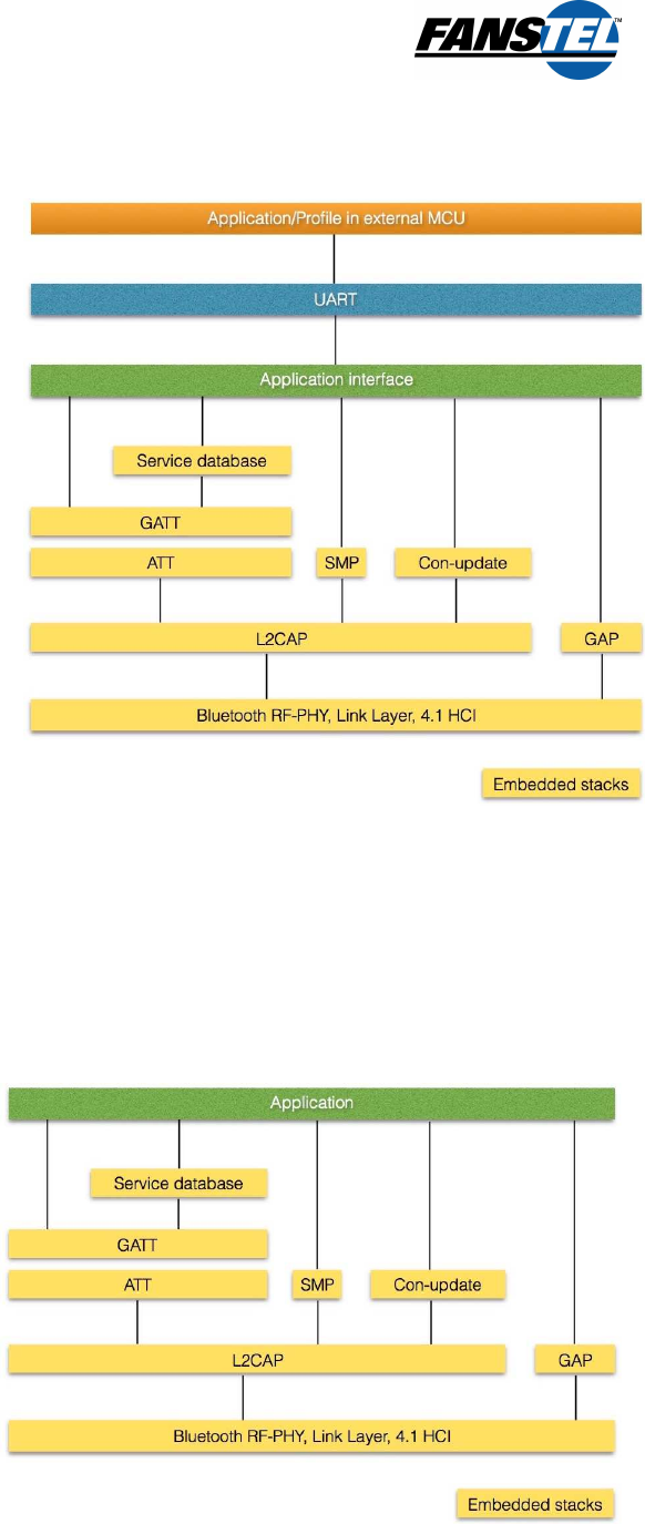
Hosted Mode
The following is BlueFan software structure
when used with an external MCU. Blocks in
yellow are embedded in Toshiba SOCs.
BlueFan module is connected to an external
MCU through a UART port. Host MCU uses
HCI (Host Control Interface) commands to
control BlueFan module.
HCI command evaluation software are
available for Windows PC and MAC. Sample
scripts for setting up communication to an
iOS or Android device is available. HCI
command control flow can be developed on
Windows PC or MAC before porting onto the
target MCU.
Standalone Mode
Application programs are developed and compiled in a Windows PC and downloaded into flash ROM
of BlueFan module. Ob booting up of module, application programs are loaded into RAM for
execution.

BlueFan BLE 4.1 Modules
Ver 0.01, draft, Jan. 2016
10
6. Module Evaluation Board
A development/evaluation board is available for each module. A quick and easy way to evaluate a
module, e.g., BS675 is to use a Windows PC or a MAC as the host processor. Connect the evaluation
board to a PC with an USB cable.
Evaluation Software for Windows PC
Evaluation software for Windows PC can be download from the following link.
https://dl.dropboxusercontent.com/u/54939426/BlueFanHCIwin.rar
After unzipping, it becomes an executable file. You need to OPEN from a MENU for the first time.
Then, you can double click the icon to open.
Evaluation Software for MAC
Evaluation software for MAC can be download from the following link.
https://dl.dropboxusercontent.com/u/54939426/BlueFanHCImac.zip
After unzipping, it becomes an executable file. You need to OPEN from a MENU for the first time.
Then, you can double click the icon to open
Android OS App
Android OS apps to evaluate communication via SPP and BLE can be downloaded from Google Play
Store by searching for BlueFan. This is a very basic app for proving communication between a PC,
BH675 module, and an Android device.
iOS App
iOS apps to evaluate communication via BLE can be downloaded from Apple App Store by searching
for BlueFan. This is a very basic app for proving communication between a PC, module, and an
Android device.

BlueFan BLE 4.1 Modules
Ver 0.01, draft, Jan. 2016
11
7. Reference Applications
Battery Power Application
Current consumption is important for battery-powered product. If a 32.768 kHz crystal is installed,
main clock can be disabled in sleep mode to reduce power consumption. Sleep clock is integrated in
BSXXX modules but not in BHXXX modules. If you need to reduce sleep mode power consumption,
add a crystal and two capacitors to the SLPXOIN and SLPXOOUT pins.
Using external BLE antenna
An external antenna is required when you need higher gain antenna or this module is hidden inside a
metal case. An external antenna can be installed for module with an integrated chip antenna. Remove
the chip antenna or order module without one. An external antenna is not supported by a module with
integrated PCB antenna, e.g., BH676CP.
8. FCC
(1) the module should not installed and operated simultaneously with other radios except additional
RF exposure was evaluated and meeting FCC requirement for simultaneously transmission.
(2) Antenna used should be limited to (PCB) type with equal or lesser antenna gain.
9. Soldering Temperature-Time Profile for Re-Flow Soldering
to be provided
10.
Cautions
Failure to follow the guidelines set forth in this document may result in degrading of the product’s
functions and damage to the product.
Design Notes
(1) Follow the conditions written in this specification, especially the control signals of this module.
(2) The supply voltage has to be free of AC ripple voltage (for example from a battery or a low noise
regulator output). For noisy supply voltages, provide a decoupling circuit (for example a ferrite in
series connection and a bypass capacitor to ground of at least 47uF directly at the module).
(3) This product should not be mechanically stressed when installed.
(4) Keep this product away from heat. Heat is the major cause of decreasing the life of these products.
(5) Avoid assembly and use of the target equipment in conditions where the products' temperature
may exceed the maximum tolerance.

BlueFan BLE 4.1 Modules
Ver 0.01, draft, Jan. 2016
12
(6) The supply voltage should not be exceedingly high or reversed. It should not carry noise and/or
spikes.
(7) this product away from other high frequency circuits.
Notes on Antenna and PCB Layout
(1) Don’t use a module with internal antenna inside a metal case.
(2) Use a module with external antenna inside a metal case. Antenna must be outside of a metal case.
(3) For PCB layout:
• Avoid running any signal line below module whenever possible,
• No ground plane below antenna,
• If possible, cut-off the portion of main board PCB below antenna.
Installation Notes
(1) Reflow soldering is possible twice based on the time-temperature profile in this data sheets. Set up
the temperature at the soldering portion of this product according to this reflow profile.
(2) Carefully position the products so that their heat will not burn into printed circuit boards or affect
the other components that are susceptible to heat.
(3) Carefully locate these products so that their temperatures will not increase due to the effects of
heat generated by neighboring components.
(4) If a vinyl-covered wire comes into contact with the products, then the cover will melt and generate
toxic gas, damaging the insulation. Never allow contact between the cover and these products to
occur.
(5) This product should not be mechanically stressed or vibrated when reflowed.
(6) If you want to repair your board by hand soldering, please keep the conditions of this chapter.
(7) Do not wash this product.
(8) Refer to the recommended pattern when designing a board.
(9) Pressing on parts of the metal cover or fastening objects to the metal will cause damage to the unit.
(10) For more details on LGA (Land Grid Array) soldering processes refer to the application note.
Usage Condition Notes
(1) Take measures to protect the unit against static electricity. If pulses or other transient loads (a
large load applied in a short time) are applied to the products, check and evaluate their operation
before assembly on the final products.
(2) Do not use dropped products.
(3) Do not touch, damage or soil the pins.

BlueFan BLE 4.1 Modules
Ver 0.01, draft, Jan. 2016
13
(4) Follow the recommended condition ratings about the power supply applied to this product.
(5) Electrode peeling strength: Do not add pressure of more than 4.9N when soldered on PCB
(6) Pressing on parts of the metal cover or fastening objects to the metal cover will cause damage.
(7) These products are intended for general purpose and standard use in general electronic
equipment, such as home appliances, office equipment, information and communication equipment.
Storage Notes
(1) The module should not be stressed mechanically during storage.
(2) Do not store these products in the following conditions or the performance characteristics of
the product, such as RF performance will be adversely affected:
• Storage in salty air or in an environment with a high concentration of corrosive gas.
• Storage in direct sunlight
• Storage in an environment where the temperature may be outside the range specified.
• Storage of the products for more than one year after the date of delivery storage period.
(3) Keep this product away from water, poisonous gas and corrosive gas.
(4) This product should not be stressed or shocked when transported.
(5) Follow the specification when stacking packed crates (max. 10).
Safety Conditions
These specifications are intended to preserve the quality assurance of products and
individual
components.
Before use, check and evaluate the operation when mounted on your products. Abide by
these specifications, without deviation when using the products. These products may short-circuit. If
electrical shocks, smoke, fire, and/or accidents involving human life are anticipated when a short
circuit occurs, then provide the following failsafe functions, as a minimum.
(1)
Ensure the safety of the whole system by installing a protection circuit and a
protection device.
(2) Ensure the safety of the whole system by installing a redundant circuit or another system to
prevent a dual fault causing an unsafe status.
Other Cautions
(1) This specification sheet is copyrighted. Reproduction of this data sheets is permissible only if
reproduction is without alteration and is accompanied by all associated warranties, conditions,
limitations, and notices.
(2) Do not use the products for other purposes than those listed.
(3) Be sure to provide an appropriate failsafe function on your product to prevent an additional
damage that may be caused by the abnormal function or the failure of the product.

BlueFan BLE 4.1 Modules
Ver 0.01, draft, Jan. 2016
14
(4) This product has been manufactured without any ozone chemical controlled under the
Montreal Protocol.
(5) These products are not intended for other uses, other than under the special conditions shown
below. Before using these products under such special conditions, check their performance and
reliability under the said special conditions carefully to determine whether or not they can be used
in such a manner.
• In liquid, such as water, salt water, oil, alkali, or organic solvent, or in places where liquid may
splash.
•
In direct sunlight, outdoors, or in a dusty environment
• In an environment where condensation occurs.
• In an environment with a high concentration of harmful gas.
(6) If an abnormal voltage is applied due to a problem occurring in other components or circuits,
replace these products with new products because they may not be able to provide normal
performance even if their electronic characteristics and appearances appear satisfactory.
(7) When you have any question or uncertainty, contact Fanstel.
11.
Packaging
Production modules are delivered in reel, 2000 modules in each reel.
12. C
ONTACT
U
S
United States:
Fanstel Corp.
7466 E. Monte Ctisto Ave. Scottsdale AZ 85260
Tel. 1 480-948-4928
Fax. 1-480-948-5459
Email: module@fanstel.com
Website: www.fanstel.com
Taiwan:
Fanstel Corp.
10F-10, 79 Xintai Wu Road
Xizhu, New Taipei City, Taiwan 22101
泛世公司
臺灣省新北市汐止區新臺五路 79 號10 樓之 10, 22101
Tel. 886-2-2698-9328
Fax. 886-2-2698-4813
Email: tp@fanstel.com

BlueFan BLE 4.1 Modules
Ver 0.01, draft, Jan. 2016
15
Website: www.fanstel.com
China:
Fanstel Technologies Corp.
11 Jiale Street
Ping-Dih, Long-Gang, Shen Zhen, GD 518117
泛世康科技(深圳)有限公司
廣東省深圳市龍崗區坪地鎮佳樂街 11 號
Tel. 86-755-8409-0928
Fax. 86-755-8409-0973
QQ. 3076221086
Email: module@fanstel.com
Website: www.fanstel.com

BlueFan BLE 4.1 Modules
Ver 0.01, draft, Jan. 2016
16
statement and RF Exposure
The final end product must be labeled in a visible area with the following: “Contains FCC ID: X8WBH676CP & IC: 4100A-
BH676CP ”.
The Original Equipment Manufacturer (OEM) must ensure that the OEM modular transmitter must be labeled with its own
FCC ID number. This includes a clearly visible label on the outside of the final product enclosure that displays the contents
shown below. If the FCC ID is not visible when the equipment is installed inside another device, then the outside of the
device into which the equipment is installed must also display a label referring to the enclosed equipment.
Federal Communications Commission (FCC) Statement
This device complies with Part 15 of the FCC Rules. Operation is subject to the following two conditions:
1) this device may not cause harmful interference, and
2) this device must accept any interference received, including interference that may cause undesired operation of the
device.
You are cautioned that changes or modifications not expressly approved by the part responsible for compliance could void
the user’s authority to operate the equipment.
This equipment has been tested and found to comply with the limits for a Class B digital device, pursuant to part 15 of the
FCC rules. These limits are designed to provide reasonable protection against harmful interference in a residential
installation. This equipment generates, uses and can radiate radio frequency energy and, if not installed and used in
accordance with the instructions, may cause harmful interference to radio communications. However, there is no
guarantee that interference will not occur in a particular installation. If this equipment does cause harmful interference to
radio or television reception, which can be determined by turning the equipment off and on, the user is encouraged to try
to correct the interference by one or more of the following measures:
-Reorient or relocate the receiving antenna.
-Increase the separation between the equipment and receiver.
-Connect the equipment into an outlet on a circuit different from that to which the receiver is connected.
-Consult the dealer or an experienced radio/TV technician for help.
FCC RF Radiation Exposure Statement:
This equipment complies with FCC radiation exposure limits set forth for an uncontrolled environment. End users must
follow the specific operating instructions for satisfying RF exposure compliance. This transmitter must not be co-located or
operating in conjunction with any other antenna or transmitter.
Canada, Industry Canada (IC) Notices
“This device complies with Industry Canada licence-exempt RSS standard(s). Operation is subject to the following two
conditions: (1) this device may not cause interference, and (2) this devicemust accept any interference, including
interference that may cause undesired operation of the device."
Canada, avis d'Industry Canada (IC)
“Le présent appareil est conforme aux CNR d'Industrie Canada applicables aux appareils radio exempts de licence.
L'exploitation est autorisée aux deux conditions suivantes : (1) l'appareil ne doit pas produire de brouillage, et (2)
l'utilisateur de l'appareil doit accepter tout brouillage radioélectrique subi, même si le brouillage est susceptible d'en
compromettre le fonctionnement."

BlueFan BLE 4.1 Modules
Ver 0.01, draft, Jan. 2016
17
The OEM integrator has to be aware not to provide information to the end user regarding how to install or remove
this RF module in the user’s manual of the end product which integrates this module. The end user manual shall
include all required regulatory information/warning as show in this manual.
(1) the module should not installed and operated simultaneously with other radios except additional RF exposure
was evaluated and meeting RSS 102 requirement for simultaneously transmission.
(2) Antenna used should be limited to same type with equal or lesser antenna gain.