Fargo Electronics OEM300 I-Class Encoder User Manual HDP820 Technical Service and Maintenance Manual
Fargo Electronics Inc I-Class Encoder HDP820 Technical Service and Maintenance Manual
UserManual.wiki
>
Fargo Electronics
>
OEM300 User Manual
User Manual
Navigation menu
Upload a User Manual
Namespaces
Wiki Guide
HTML
PDF
Info
Views
User Manual
Discussion / Help
Navigation
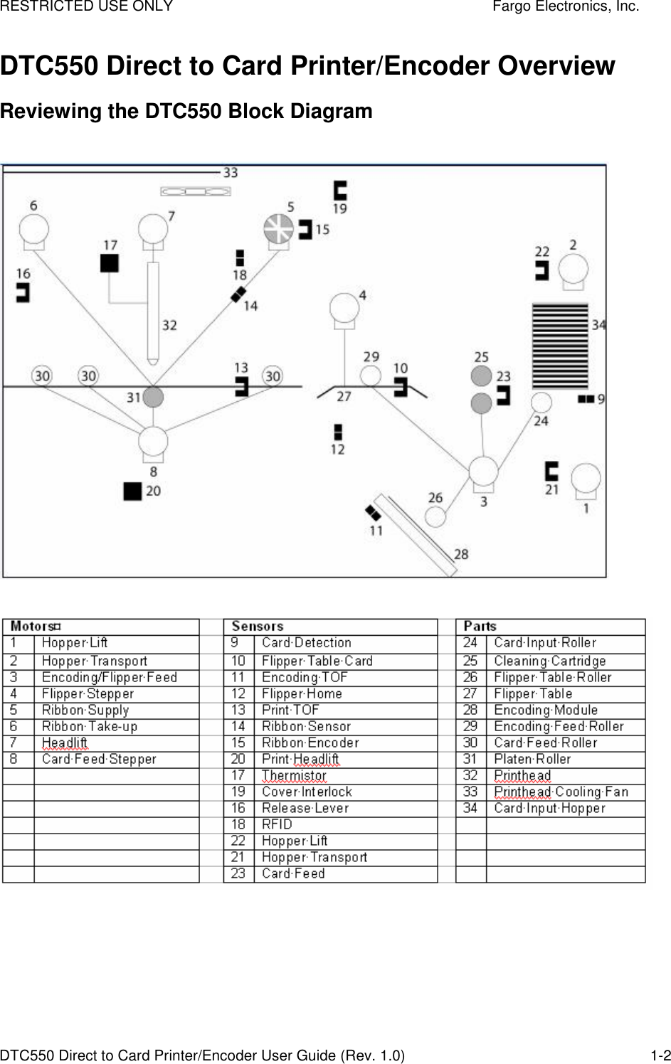
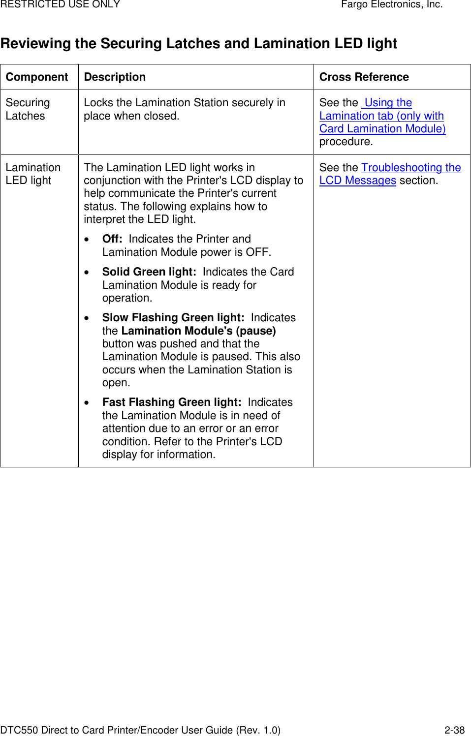
![RESTRICTED USE ONLY Fargo Electronics, Inc. DTC550 Direct to Card Printer/Encoder User Guide (Rev. 1.0) 2-44 Reviewing the Module’s Programmed Default Temperature Term Description Reference Programmed Default Temperature Upon initial power up, the Lamination Module is programmed to heat the Lamination Roller up to its default temperature. Target Temperature: If a print job is sent while the Lamination Module is heating up, the Printer's LCD display will read Laminator Warming. This will alternate with LAM Temp: [current] [target] which shows the current temperature of the Lamination Roller and the target temperature it is trying to reach. (Note: This indicates that the lamination Roller is heating to its preset temperature.) Initial Heating Process: The initial heating process will generally take about 3 to 4 minutes. (Note: The LCD display will read Laminator Warming or Laminator Cooling whenever the Lamination Roller is heating up or cooling down to the prescribed temperature. When the Lamination Module has reached its target temperature, lamination will begin.) See the Using the Lamination tab (only with Card Lamination Module) procedure.](https://usermanual.wiki/Fargo-Electronics/OEM300/User-Guide-581592-Page-61.png)