Fargo Electronics OEM300 I-Class Encoder User Manual HDP820 Technical Service and Maintenance Manual
Fargo Electronics Inc I-Class Encoder HDP820 Technical Service and Maintenance Manual
User Manual

DTC550 Direct to Card
Printer/Encoder User Guide (Rev.
1.0)
Part Number: L000683

RESTRICTED USE ONLY Fargo Electronics, Inc.
DTC550 Direct to Card Printer/Encoder User Guide (Rev. 1.0) ii
DTC550 Direct to Card Printer/Encoder User Guide (Rev. 1.0), property of FARGO
Electronics, Incorporated
Copyright 2002, 2003, 2004, 2005, 2006 by FARGO Electronics, Incorporated. All rights
reserved. Printed in the United States of America. Exclusive permission is granted to
authorized resellers of FARGO products to reproduce and distribute this copyrighted
document to authorized FARGO customers, who have signed a “no disclosure agreement”
regarding the restricted, proprietary use of said document.
The revision number for this document will be updated to reflect changes, corrections,
updates and enhancements to this document.
Revision Control
Number Date Document Title
Revision 1.0 1 July 2005 DTC550 Direct to Card Printer/Encoder User Guide
(Rev. 1.0)
These reference documents were thoroughly reviewed to provide FARGO with professional
and international standards, requirements, guidelines and models for our technical, training
and user documentation. At all times, the Copyright Protection Notice for each document
was adhered to within our FARGO documentation process. This reference to other
documents does not imply that FARGO is an ISO-certified company at this time.
ANSI/ISO/ASQ Q9001-2000 American National Standard, (sub-title) Quality Management
Systems - Requirements (published by the American Society of Quality, Quality Press,
P.O. Box 3005, Milwaukee, Wisconsin 53201-3005)
The ASQ ISO 9000:2000 Handbook (editors, Charles A. Cianfrani, Joseph J. Tsiakals and
John E. West; Second Edition; published by the American Society of Quality, Quality
Press, 600 N. Plankinton Avenue, Milwaukee, Wisconsin 53203)
Juran's Quality Handbook (editors, Joseph M. Juran and A. Blanton Godfrey; Fifth Edition,
McGraw-Hill)
Any questions regarding changes, corrections, updates or enhancements to this document
should be forwarded to:
FARGO Electronics, Incorporated
Support Services
6533 Flying Cloud Drive
Eden Prairie, MN 55344 (USA)
(952) 941-9470
(800) 459-5636
FAX: (952) 941-7836
www.fargo.com
E-mail: sales@fargo.com
RESTRICTED USE ONLY Fargo Electronics, Inc.
DTC550 Direct to Card Printer/Encoder User Guide (Rev. 1.0) iii
Table of Contents
Section 1: Introduction _____________________________________________________1-1
How to use the manual _______________________________________________________________ 1-1
DTC550 Direct to Card Printer/Encoder Overview _________________________________________ 1-2
Reviewing the DTC550 Block Diagram________________________________________________ 1-2
Reviewing DTC550 Sequence of Operations____________________________________________ 1-3
Reviewing DTC550 Boot up Sequence ________________________________________________ 1-5
Reviewing the Lamination Module Sequence of Operations ________________________________ 1-6
Reviewing the Lamination Module Boot up Sequence ____________________________________ 1-8
Section 2: Specifications____________________________________________________2-1
Regulatory Compliances ______________________________________________________________ 2-1
Agency Listings_____________________________________________________________________ 2-2
FCC Rules _________________________________________________________________________ 2-2
Safety Messages (review carefully)______________________________________________________ 2-3
Technical Specifications ______________________________________________________________ 2-4
Functional Specifications ____________________________________________________________ 2-11
Printer Components - Descriptions___________________________________________________ 2-13
Printer Components: LCD and Softkey Control Pad_____________________________________ 2-21
Printer Components: Print Ribbons__________________________________________________ 2-26
Printer Components: Resin-Only Print Ribbons ________________________________________ 2-27
Printer Components: Dye-Sublimation Print Ribbons____________________________________ 2-28
Printer Components: Dye-Sublimation/Resin Print Ribbons_______________________________ 2-29
Printer Components: Blank Cards ___________________________________________________ 2-30
Printer Components: Upgraded 81754 PVC Cards ______________________________________ 2-32
Printer Components: Card Input and Output Hoppers____________________________________ 2-34
Reviewing the Card Lamination Module ________________________________________________ 2-35
Reviewing the Lamination Top Cover and Station_______________________________________ 2-37
Reviewing the Securing Latches and Lamination LED light _______________________________ 2-38
Reviewing the Cancel button _______________________________________________________ 2-39
Reviewing the Resume (pause) button ________________________________________________ 2-40
Reviewing the Rejection Card Hopper and Card Output Hopper____________________________ 2-41
Reviewing the Module and Printer interaction__________________________________________ 2-42
Reviewing the Module and LCD display interaction _____________________________________ 2-43
Reviewing the Module’s Programmed Default Temperature_______________________________ 2-44
Reviewing the Laminator Temperature Adjustment______________________________________ 2-45
Reviewing the Overlaminates _________________________________________________________ 2-46
Reviewing the Thermal Transfer Film and PolyGuard Overlaminates________________________ 2-46
Reviewing the CR-90 or CR-100 Patch Size ___________________________________________ 2-47
Reviewing the Overlaminate Design _________________________________________________ 2-47
Reviewing the Visual Security Solutions ________________________________________________ 2-48
VeriMarkTM Cards - 2-D holographic foil application ___________________________________ 2-48
Custom HoloMarkTM Cards _______________________________________________________ 2-48
Visual Security - Card Stock Part Numbers ____________________________________________ 2-48
Visual Security - Fargo Certified Overlaminates (Special Order in 50 quantity minimum)________ 2-48
Visual Security Card Stock - Tolerances ______________________________________________ 2-49
VeriMarkTM - Application Specifications_____________________________________________ 2-49
HoloMarkTM and Custom HoloMarkTM - Application Specifications ______________________ 2-49
Section 3: Secure Print Security Suite ________________________________________3-49
Overview_________________________________________________________________________ 3-49
Print Notification Application _______________________________________________________ 3-2
Security Imaging Application________________________________________________________ 3-2
Print Diagnostics Application________________________________________________________ 3-2
Supplies e-Ordering Application _____________________________________________________ 3-2
RESTRICTED USE ONLY Fargo Electronics, Inc.
DTC550 Direct to Card Printer/Encoder User Guide (Rev. 1.0) iv
Password Control Application _______________________________________________________ 3-2
Print Security Suite – Main Window __________________________________________________ 3-3
SecureMark Media ________________________________________________________________ 3-3
Section 4: Setup and Installation Procedures ______________Error! Bookmark not defined.
Table of Contents ____________________________________________ Error! Bookmark not defined.
Printer Setup and Installation ___________________________________ Error! Bookmark not defined.
Choosing a Good Location___________________________________ Error! Bookmark not defined.
About Moisture Condensation ________________________________ Error! Bookmark not defined.
Unpacking and Inspection ___________________________________ Error! Bookmark not defined.
Safety Messages (review carefully)_______________________________ Error! Bookmark not defined.
Introduction_________________________________________________ Error! Bookmark not defined.
Time Requirement _________________________________________ Error! Bookmark not defined.
System Requirements _______________________________________ Error! Bookmark not defined.
Inspection ________________________________________________ Error! Bookmark not defined.
Unpacking the Printer_______________________________________ Error! Bookmark not defined.
Loading Supplies_____________________________________________ Error! Bookmark not defined.
Loading the Print Ribbon ____________________________________ Error! Bookmark not defined.
Inserting the Card Cleaning Cartridge __________________________ Error! Bookmark not defined.
Loading the Overlaminate ___________________________________ Error! Bookmark not defined.
Connecting power to the DTC550 Printer _______________________ Error! Bookmark not defined.
Loading the Blank Cards ____________________________________ Error! Bookmark not defined.
Printer Driver Installation Procedure______________________________ Error! Bookmark not defined.
Installing the DTC550 Printer Driver___________________________ Error! Bookmark not defined.
Installing the SecureMark Application ____________________________ Error! Bookmark not defined.
Printing a Test Print Image _____________________________________ Error! Bookmark not defined.
Printer Transport _____________________________________________ Error! Bookmark not defined.
Moving the Printer to another location__________________________ Error! Bookmark not defined.
Section 5: General Troubleshooting _____________________Error! Bookmark not defined.
Reviewing the LCD display and LED light_________________________ Error! Bookmark not defined.
Safety Messages (review carefully)_______________________________ Error! Bookmark not defined.
Troubleshooting the LCD Messages ______________________________ Error! Bookmark not defined.
Verifying the Encoding Settings for DTC550 Series Card Printer and Encoders_ Error! Bookmark not
defined.
Communications Errors________________________________________ Error! Bookmark not defined.
Resolving the Communication Errors___________________________ Error! Bookmark not defined.
Card Feeding Errors __________________________________________ Error! Bookmark not defined.
Resolving the Card Feeding Errors_____________________________ Error! Bookmark not defined.
Resolving the Card Jam on the Flipper Table_____________________ Error! Bookmark not defined.
Resolving the Card Hopper Jam Error Message___________________ Error! Bookmark not defined.
Resolving the Card Hopper Empty Error Message_________________ Error! Bookmark not defined.
Encoding Errors______________________________________________ Error! Bookmark not defined.
Resolving the No Magnetic Encoder Error Message _______________ Error! Bookmark not defined.
Resolving the No ENC Response Error Message__________________ Error! Bookmark not defined.
Resolving the Failed Magnetic Encoder Error Message_____________ Error! Bookmark not defined.
Resolving the No Prox Encoder Error Message ___________________ Error! Bookmark not defined.
Resolving the No Smart Encoder Error Message __________________ Error! Bookmark not defined.
Resolving the Failed Smart Encode Error Message ________________ Error! Bookmark not defined.
Removing the Card Jam in the Printer’s Magnetic Encoding Area ____ Error! Bookmark not defined.
Removing the Card Jam in the Printer’s Smart Card Encoding Area___ Error! Bookmark not defined.
Resolving the Printer not reading Encoded Magnetic Track Data _____ Error! Bookmark not defined.
Resolving the Magnetic Stripe Data being printed on a Card problem _ Error! Bookmark not defined.
Printing Process Errors ________________________________________ Error! Bookmark not defined.
Resolving the Ribbon Alignment Error Message __________________ Error! Bookmark not defined.
Resolving the Print Ribbon Error Message ______________________ Error! Bookmark not defined.
RESTRICTED USE ONLY Fargo Electronics, Inc.
DTC550 Direct to Card Printer/Encoder User Guide (Rev. 1.0) v
Resolving the Print Ribbon Out Error Message ___________________ Error! Bookmark not defined.
Resolving the Ribbon Jam/Broken Error Message_________________ Error! Bookmark not defined.
Resolving the Wrong Print Ribbon Error Message ________________ Error! Bookmark not defined.
Resolving the Unknown Ribbon Type Error Message ______________ Error! Bookmark not defined.
Resolving the Headlift Error Message __________________________ Error! Bookmark not defined.
Resolving the Printer pausing between panels error________________ Error! Bookmark not defined.
Resolving the Printhead Temp Error Message ____________________ Error! Bookmark not defined.
Resolving the Flipper Alignment Error Message __________________ Error! Bookmark not defined.
Firmware Errors _____________________________________________ Error! Bookmark not defined.
Resolving the Update Firmware Now __________________________ Error! Bookmark not defined.
Resolving an Upgrade Failed error_____________________________ Error! Bookmark not defined.
Resolving a Program Exception Error __________________________ Error! Bookmark not defined.
Diagnosing the Image Problems _________________________________ Error! Bookmark not defined.
Resolving the Pixel failure problems ___________________________ Error! Bookmark not defined.
Resolving the Card surface debris problems _____________________ Error! Bookmark not defined.
Resolving the incorrect Image Darkness problems ________________ Error! Bookmark not defined.
Resolving the Ribbon wrinkle problems ________________________ Error! Bookmark not defined.
Resolving the excessive Resin Printing problems _________________ Error! Bookmark not defined.
Resolving the incomplete Resin Printing problems ________________ Error! Bookmark not defined.
Resolving the cut off or off-center Card Image problems ___________ Error! Bookmark not defined.
Resolving the poor Image Quality problems _____________________ Error! Bookmark not defined.
Printing a Test Image _________________________________________ Error! Bookmark not defined.
Reviewing the Gray/Align YMC/K Self-Test ____________________ Error! Bookmark not defined.
Reviewing the Color/Resin YMCK Self-Test ____________________ Error! Bookmark not defined.
Reviewing the Color Bars YMC Self-Test_______________________ Error! Bookmark not defined.
Reviewing the Card Count Self-Test ___________________________ Error! Bookmark not defined.
Reviewing the Magnetic Test option ___________________________ Error! Bookmark not defined.
Section 6: Card Lamination Module _____________________Error! Bookmark not defined.
Safety Messages (review carefully)_______________________________ Error! Bookmark not defined.
Loading the Overlaminate______________________________________ Error! Bookmark not defined.
Adjusting the Card Lamination Module ___________________________ Error! Bookmark not defined.
Adjusting the Card Flattener__________________________________ Error! Bookmark not defined.
Adjusting the Card Guide Rail ________________________________ Error! Bookmark not defined.
Adjusting the Internal Card Guide _____________________________ Error! Bookmark not defined.
Attaching the Card Lamination Module _________________________ Error! Bookmark not defined.
Section 7: Printer Adjustments__________________________Error! Bookmark not defined.
Safety Messages (review carefully)_______________________________ Error! Bookmark not defined.
Adjusting the Internal Card Guide _____________________________ Error! Bookmark not defined.
Printer Driver options _________________________________________ Error! Bookmark not defined.
Using the Card tab____________________________________________ Error! Bookmark not defined.
Selecting the Card Size______________________________________ Error! Bookmark not defined.
Using the Card Hopper Selection option ________________________ Error! Bookmark not defined.
Adjusting the Orientation Option ______________________________ Error! Bookmark not defined.
Selecting the number of Copies _______________________________ Error! Bookmark not defined.
Using the Diagnostics button under the Card tab __________________ Error! Bookmark not defined.
Using the Clean Printer Option________________________________ Error! Bookmark not defined.
Using the Test Print button___________________________________ Error! Bookmark not defined.
Using the About button______________________________________ Error! Bookmark not defined.
Using the Device Options tab ___________________________________ Error! Bookmark not defined.
Adjusting for the Ribbon Type option __________________________ Error! Bookmark not defined.
Selecting the Auto Ribbon Select option ________________________ Error! Bookmark not defined.
Adjusting for the Color matching______________________________ Error! Bookmark not defined.
Adjusting for the Resin Dither ________________________________ Error! Bookmark not defined.
Using the Print Both Sides option______________________________ Error! Bookmark not defined.
RESTRICTED USE ONLY Fargo Electronics, Inc.
DTC550 Direct to Card Printer/Encoder User Guide (Rev. 1.0) vi
Using the Split 1 Set of Ribbon Panels option ____________________ Error! Bookmark not defined.
Using the Print Back Side First option __________________________ Error! Bookmark not defined.
Using the Print on Back Side Only option _______________________ Error! Bookmark not defined.
Using the Rotate Front by 180 Degrees option____________________ Error! Bookmark not defined.
Using the Rotate Back by 180 Degrees option ____________________ Error! Bookmark not defined.
Using the Disable Printing option______________________________ Error! Bookmark not defined.
Using the Image Color tab______________________________________ Error! Bookmark not defined.
Using the Resin Heat (K) option (Front and Back) ________________ Error! Bookmark not defined.
Using the Overlay Heat (O) option_____________________________ Error! Bookmark not defined.
Using the Image Color option and Default button _________________ Error! Bookmark not defined.
Using the Calibrate tab ________________________________________ Error! Bookmark not defined.
Using the Image Position Controls_____________________________ Error! Bookmark not defined.
Using the Sensors button ____________________________________ Error! Bookmark not defined.
Using the Settings button ____________________________________ Error! Bookmark not defined.
Using the Printer Calibration Utility ______________________________ Error! Bookmark not defined.
Using the Image Darkness Option _____________________________ Error! Bookmark not defined.
Using the Print Top of Form Option____________________________ Error! Bookmark not defined.
Using the Print End of Form Option____________________________ Error! Bookmark not defined.
Using the Print Left of Form Option ___________________________ Error! Bookmark not defined.
Using the Mag Top of Form Option____________________________ Error! Bookmark not defined.
Using the Ribbon Tension Option _____________________________ Error! Bookmark not defined.
Using the Magnetic Encoding tab ________________________________ Error! Bookmark not defined.
Encoding the Coercivity and Magnetic Track Selection ____________ Error! Bookmark not defined.
Using the Magnetic Track Selection option ______________________ Error! Bookmark not defined.
Reviewing the Enable MLE Support checkbox ___________________ Error! Bookmark not defined.
Using the Magnetic Track Options_____________________________ Error! Bookmark not defined.
Using the Bit Density radio buttons ____________________________ Error! Bookmark not defined.
Using the Character Size radio buttons__________________________ Error! Bookmark not defined.
Using the ASCII Offset _____________________________________ Error! Bookmark not defined.
Using the LRC Generation radio buttons ________________________ Error! Bookmark not defined.
Using the Character Parity radio buttons ________________________ Error! Bookmark not defined.
Reviewing the Shift Data Left ________________________________ Error! Bookmark not defined.
Reviewing the ISO Track Locations____________________________ Error! Bookmark not defined.
Reviewing the Sample String _________________________________ Error! Bookmark not defined.
Sending the Track Information________________________________ Error! Bookmark not defined.
Reviewing the ASCII Code and Character Table__________________ Error! Bookmark not defined.
Using the Lamination tab (only with Card Lamination Module) ________ Error! Bookmark not defined.
Selecting the Lamination Position _____________________________ Error! Bookmark not defined.
Selecting the Lamination Side ________________________________ Error! Bookmark not defined.
Selecting the Lamination Type________________________________ Error! Bookmark not defined.
Selecting the Lamination Type________________________________ Error! Bookmark not defined.
Adjusting the Transfer Dwell Time and Transfer Temperature _______ Error! Bookmark not defined.
Selecting the Sensors button and Defaults button__________________ Error! Bookmark not defined.
Using the Overlay/Print Area tab ________________________________ Error! Bookmark not defined.
Using the Overlay/Print Area dropdown menu ___________________ Error! Bookmark not defined.
Using the Overlay/Print Area _________________________________ Error! Bookmark not defined.
Using Security Options (Visual Security Solutions)________________ Error! Bookmark not defined.
Selecting Orientation - Landscape under Card tab _________________ Error! Bookmark not defined.
Selecting the Visual Security Solutions dropdown menu (A to D) ____ Error! Bookmark not defined.
Selecting Orientation - Portfolio under Card tab __________________ Error! Bookmark not defined.
Selecting the Visual Security Solutions dropdown menu (E to H)_____ Error! Bookmark not defined.
Selecting the VeriMark radio button ___________________________ Error! Bookmark not defined.
Selecting the HoloMark radio button ___________________________ Error! Bookmark not defined.
Reviewing the Custom VeriMark Card _________________________ Error! Bookmark not defined.
Reviewing the Custom HoloMark Card _________________________ Error! Bookmark not defined.
Using the K Panel Resin tab ____________________________________ Error! Bookmark not defined.
RESTRICTED USE ONLY Fargo Electronics, Inc.
DTC550 Direct to Card Printer/Encoder User Guide (Rev. 1.0) vii
Selecting the Full Card with the K Panel Resin tab ________________ Error! Bookmark not defined.
Selecting the Defined Area(s) with the K Panel Resin tab ___________ Error! Bookmark not defined.
Selecting the Undefined Area(s) with the K Panel Resin tab _________ Error! Bookmark not defined.
Defining the Area to activate the Card Grid ______________________ Error! Bookmark not defined.
Measuring the Total Card area ________________________________ Error! Bookmark not defined.
Defining the positioning of the area on the Card __________________ Error! Bookmark not defined.
Selecting the Print YMC under the K and Print K Only options ______ Error! Bookmark not defined.
Using the Printer Supplies tab___________________________________ Error! Bookmark not defined.
Reviewing the Ribbon Information ____________________________ Error! Bookmark not defined.
Reviewing the Ribbon Level Indicator__________________________ Error! Bookmark not defined.
Section 8: Cleaning___________________________________Error! Bookmark not defined.
Safety Messages (review carefully)_______________________________ Error! Bookmark not defined.
Introduction_________________________________________________ Error! Bookmark not defined.
Supplies Included ____________________________________________ Error! Bookmark not defined.
Cleaning the Printhead (D855055)_____________________________ Error! Bookmark not defined.
Replacing the Card Cleaning Roller____________________________ Error! Bookmark not defined.
Cleaning the Platen and Card Feed Rollers ______________________ Error! Bookmark not defined.
Cleaning the Platen_________________________________________ Error! Bookmark not defined.
Cleaning the Printer's Exterior ________________________________ Error! Bookmark not defined.
Cleaning the Printer's Interior_________________________________ Error! Bookmark not defined.
Section 9: Diagnostic Tool Utility________________________Error! Bookmark not defined.
Table of Contents ____________________________________________ Error! Bookmark not defined.
Using the Diagnostic Utility tabs ________________________________ Error! Bookmark not defined.
Selecting the Print Spooler tab in the Diagnostics Utility ___________ Error! Bookmark not defined.
Selecting the Firmware Updates tab in the Diagnostics Utility _______ Error! Bookmark not defined.
Downloading Firmware Updates ______________________________ Error! Bookmark not defined.
Selecting the Firmware File __________________________________ Error! Bookmark not defined.
Placing the Printer in Upgrade Mode ___________________________ Error! Bookmark not defined.
Sending the Firmware File ___________________________________ Error! Bookmark not defined.
Selecting the Mechanics tab in the Diagnostics Utility________________ Error! Bookmark not defined.
Selecting the Move the Flipper Table to Mag Position button ________ Error! Bookmark not defined.
Selecting the Move Flipper Table to Home Position button__________ Error! Bookmark not defined.
Selecting the Toggle the Card Hopper Position button______________ Error! Bookmark not defined.
Selecting the Raise the Printhead button ________________________ Error! Bookmark not defined.
Selecting the Lower the Printhead button________________________ Error! Bookmark not defined.
Selecting the Calibrate the Ribbon Sensor button _________________ Error! Bookmark not defined.
Selecting the Self Tests tab in the Diagnostics Utility ______________ Error! Bookmark not defined.
Selecting the Barcode Test Card button _________________________ Error! Bookmark not defined.
Selecting the YMCK Test Card Self Test button __________________ Error! Bookmark not defined.
Selecting the Magnetic Self Test button _________________________ Error! Bookmark not defined.
Selecting the Color Bar Self Test button ________________________ Error! Bookmark not defined.
Selecting the Alignment Self Test button________________________ Error! Bookmark not defined.
Selecting the Alignment Self Test button________________________ Error! Bookmark not defined.
Selecting the Card Samples tab in the Diagnostics Utility _____________ Error! Bookmark not defined.
Selecting the Magnetic Encoding tab in the Diagnostics Utility ______ Error! Bookmark not defined.
Selecting the Help button in the Diagnostics Utility _______________ Error! Bookmark not defined.
Selecting the About button in the Diagnostics Utility ______________ Error! Bookmark not defined.
Selecting the Exit button in the Diagnostics Utility ________________ Error! Bookmark not defined.
Using the Track 1, Track 2 and Track 3 text boxes ________________ Error! Bookmark not defined.
Selecting the Auto Fill Track data button________________________ Error! Bookmark not defined.
Selecting the Encode button __________________________________ Error! Bookmark not defined.
Selecting the Clear button____________________________________ Error! Bookmark not defined.
Reviewing the ISO Track Locations____________________________ Error! Bookmark not defined.
Sending the Track Information________________________________ Error! Bookmark not defined.
RESTRICTED USE ONLY Fargo Electronics, Inc.
DTC550 Direct to Card Printer/Encoder User Guide (Rev. 1.0) viii
Reviewing the Sample String _________________________________ Error! Bookmark not defined.
Reviewing the ASCII Code and Character Table__________________ Error! Bookmark not defined.
Section 10: Packing the DTC550 Card Printer _____________Error! Bookmark not defined.
Section 11: Board Level Diagnostics _____________________Error! Bookmark not defined.
Board Errors ________________________________________________ Error! Bookmark not defined.
Resolving the EE Memory Error ______________________________ Error! Bookmark not defined.
Resolving the EE Checksum Error_____________________________ Error! Bookmark not defined.
Resolving the SDRAM Memory Error__________________________ Error! Bookmark not defined.
Resolving the FPGA Error ___________________________________ Error! Bookmark not defined.
Sensor Testing_______________________________________________ Error! Bookmark not defined.
Reviewing the Sensor Location and Voltages ____________________ Error! Bookmark not defined.
Reviewing the DTC550 EE Settings ______________________________ Error! Bookmark not defined.
Section 12: LCD On-Line Menu Navigation_______________Error! Bookmark not defined.
Entering the LCD Menu and selecting an Option ____________________ Error! Bookmark not defined.
Using the Softkey and Scroll buttons ___________________________ Error! Bookmark not defined.
Accessing the Menu Option Structure Tree_________________________ Error! Bookmark not defined.
Selecting from the Menu Option Structure Tree___________________ Error! Bookmark not defined.
Using the LCD Menu _________________________________________ Error! Bookmark not defined.
Printing the Self-test________________________________________ Error! Bookmark not defined.
Reviewing the Gray/Align YMC and Gray/Align YMC/K Self-Test___ Error! Bookmark not defined.
Reviewing the Color/Resin YMCK Self-Test ____________________ Error! Bookmark not defined.
Reviewing the Card Count YMC Self-Test ______________________ Error! Bookmark not defined.
Reviewing the Standard Resin Self-Test ________________________ Error! Bookmark not defined.
Using the Magnetic Test option (only with Magnetic Encoding Module) ______ Error! Bookmark not
defined.
Setting up the Printer _______________________________________ Error! Bookmark not defined.
Print TOF and Print EOF Alignment Procedures ____________________ Error! Bookmark not defined.
Preparing to Adjust the Print TOF and Print EOF _________________ Error! Bookmark not defined.
Setting the Print TOF _______________________________________ Error! Bookmark not defined.
Setting the Print EOF _______________________________________ Error! Bookmark not defined.
Adjusting the Ribbon Tension ________________________________ Error! Bookmark not defined.
Setting the Printhead Resistance_______________________________ Error! Bookmark not defined.
Adjusting the Image Darkness ________________________________ Error! Bookmark not defined.
Changing the Encoder Settings________________________________ Error! Bookmark not defined.
Adjusting the Magnetic TOF _________________________________ Error! Bookmark not defined.
Changing the Hopper Settings ________________________________ Error! Bookmark not defined.
Changing the BAUD Rate Settings ____________________________ Error! Bookmark not defined.
Adjusting the Flipper Offset__________________________________ Error! Bookmark not defined.
Viewing the Report Supplies _________________________________ Error! Bookmark not defined.
Using the Show the Error Count Tool __________________________ Error! Bookmark not defined.
Showing the Card Count_____________________________________ Error! Bookmark not defined.
Selecting the System Upgrade (Firmware Upgrade) _______________ Error! Bookmark not defined.
Section 13: Firmware Updates __________________________Error! Bookmark not defined.
Firmware Updater Application Program ___________________________ Error! Bookmark not defined.
Downloading Firmware Updates_________________________________ Error! Bookmark not defined.
Selecting the Firmware File_____________________________________ Error! Bookmark not defined.
Placing the Printer in Upgrade Mode _____________________________ Error! Bookmark not defined.
Sending the Firmware File _____________________________________ Error! Bookmark not defined.
Updating the Printer's Firmware _________________________________ Error! Bookmark not defined.
Updating the Main Firmware _________________________________ Error! Bookmark not defined.
Updating the LCD Firmware _________________________________ Error! Bookmark not defined.
Section 14: Fargo Technical Support ____________________Error! Bookmark not defined.
RESTRICTED USE ONLY Fargo Electronics, Inc.
DTC550 Direct to Card Printer/Encoder User Guide (Rev. 1.0) ix
Contacting Fargo Technical Support______________________________ Error! Bookmark not defined.
Reading the Serial Numbers on a Fargo Printer _____________________ Error! Bookmark not defined.
Finding out when a Fargo Card Printer was manufactured __________ Error! Bookmark not defined.
Reviewing Example No. 1: Serial Number 80453289______________ Error! Bookmark not defined.
Reviewing Example No. 2: Serial Number A1280224 _____________ Error! Bookmark not defined.
Section 15: Reviewing Spare Parts Lists __________________Error! Bookmark not defined.
Reviewing the Spare Parts List for DTC 500 Series Card Printer _____ Error! Bookmark not defined.
Reviewing the Spare Parts List for the DTC550 LAM______________ Error! Bookmark not defined.
Section 16: Glossary of Terms __________________________Error! Bookmark not defined.
Section 17: Index_____________________________________Error! Bookmark not defined.

RESTRICTED USE ONLY Fargo Electronics, Inc.
DTC550 Direct to Card Printer/Encoder User Guide (Rev. 1.0) 1-1
Section 1: Introduction
How to use the manual
The DTC550 Direct to Card Printer/Encoder User Guide (Rev. 1.0) is designed to provide
Installers and Technicians with quick, efficient lookup of related procedures, components and
terms. The manual can be used effectively either in soft or hard copy, depending on the
preference of the Installer or Technician.
Manual Description
Sequence of Operations,
Glossary of Terms and
Technical/Functional
Specifications (hyper-linked)
You can go directly to the Sequence of Operations,
Glossary of Terms, Technical Specifications and
Functional Specifications to learn how to use the
processes, procedures, functions and windows for the
DTC550 Direct to Card Printer/Encoder within concise,
correlative tables.
Table of Contents (hyper-
linked) You can use the automated Table of Contents to quickly
locate, for example, an error message, a procedure, the
index or an appendix.
Troubleshooting,
Replacement, Removal,
Diagnostic and Navigation
Procedures (in hyper-linked
Sections)
You can go directly to Specifications, General
Troubleshooting, Printer Adjustments, Parts Replacement,
Printer Packing, Board Level Diagnostics, LCD On-Line
Menu Navigation and Firmware Updates to find
troubleshooting, removal and replacement procedures.
The section titles are always labeled according to their
function for consistent usage.
Cross-Referencing (hyper-
linked) You can use the cross-referencing links to quickly locate,
for example, an error message or a procedure.
Comprehensive Index
(hyper-linked) You can use the Comprehensive Index to quickly locate
information on the DTC550 Direct to Card Printer/Encoder,
relating to a specification, a procedural step, a window or
screen, a component, a term, a qualifier or a related
feature to this Printer.
Appendices You can use Appendix A and B to locate information
relating to engineering drawings and technical updates,
which are specific to the DTC550 Direct to Card
Printer/Encoder.
RESTRICTED USE ONLY Fargo Electronics, Inc.
DTC550 Direct to Card Printer/Encoder User Guide (Rev. 1.0) 1-2
DTC550 Direct to Card Printer/Encoder Overview
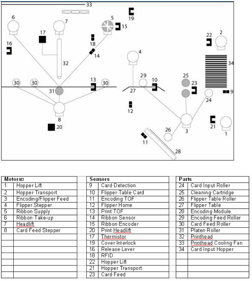
Reviewing the DTC550 Block Diagram

RESTRICTED USE ONLY Fargo Electronics, Inc.
DTC550 Direct to Card Printer/Encoder User Guide (Rev. 1.0) 1-3
Reviewing DTC550 Sequence of Operations
The following sequence describes a DTC550 doing a dual sided full color print job with
magnetic encoding.
Step
Process
1 The File information is received from the PC.
2 The Flipper Stepper activates and rotates the Flipper Table until the Flipper Home
Sensor is activated.
3 The Flipper Stepper rotates the Flipper Table back a specific number of steps
(based on the Flipper Offset setting) to return the Flipper Table to a level position.
4 The Card Detection Sensor detects the presence of a Card in the exception feed.
5 The Hopper Lift Motor activates and lowers the Card Hopper until the Hopper Lift
Sensor detects a change in state.
6 The Card Detection Sensor detects the presence of a Card.
If no card is seen, the following takes place:
a. The Hopper Lift Motor activates and raises the Card Hopper until the Hopper
Lift Sensor detects a change in state.
b. The Hopper Transport Motor activates and moves to the other Hopper until
the Hopper Position Sensor detects a change in state.
c. The Hopper Lift Motor activates and lowers the card Hopper until the Hopper
Lift Sensor is activated.
d. The Card Detection Sensor detects the presence of a Card.
7 The Card Feed Stepper activates and feeds a card through the Cleaning Roller
and onto the Flipper Table.
8 The Flipper Stepper rotates the Flipper Table a certain number of steps (based on
the Encoder Angle setting) to position the card for Encoding.
9 The Encoder/Flipper Feed Motor activates until the Card passes the Encoding
TOF Sensor.
10 The Encoding Feed Motor feeds the Card back to the Flipper Table while the
Magnetic Encoding Head transfers data onto the Magnetic Stripe.
11 Repeat Steps 9 to 10 for each Encoding and Verification pass.
Continued on the next page

RESTRICTED USE ONLY Fargo Electronics, Inc.
DTC550 Direct to Card Printer/Encoder User Guide (Rev. 1.0) 1-4
Reviewing DTC550 Sequence of Operations (continued)
Step
Process
12 The Card is centered on the Flipper Table based on input from the Flipper Table
Card Sensor.
13 The Flipper Stepper rotates the Flipper Table a specific number of steps (based on
the Flipper Offset setting) to the Home the Flipper Table.
14 The Card Feed Motor feeds the Card to the Print TOF Sensor.
15 The Ribbon Drives turn ON and move. All Stop. (Note: The Print Ribbon
Encoder is active during this step.)
16 The Headlift Motor engages and moves the printhead down until the Headlift
Sensor is activated. All Stop.
17 The Fan turns ON (as required) and blows cool air over the Printhead.
(Note: The Printhead Thermistor determinates the Printhead Temperature.)
18 Ribbon Drive and Card feed Motors activate and the printhead burns image data
until the image data is depleted. All Stop. (Note: The Ribbon Encoder is active
during this step.)
19 The Headlift Motor engages, moving the printhead up until the Headlift Sensor is
activated. All Stop.
20 The Card Feed Motor feeds the Card back to the Print TOF Sensor.
21 Repeat steps 14 to 20 for the appropriate Number of Color/Overlay Panels.
22 The Card Feed Motor transports the Card back to the Flipper Table.
23 The Flipper Stepper rotates in order to invert the Card.
24 The Card Feed Motor activates and moves the card to the Print TOF Sensor. All
Stop.
25 The Flipper Stepper rotates to return the Flipper Table to a level position.
26 Repeat Steps 14 to 20 for the appropriate Number of Color/Overlay Panels.
27 The Card Feed Motor activates to feed the Card out of the Printer.
Continued on the next page

RESTRICTED USE ONLY Fargo Electronics, Inc.
DTC550 Direct to Card Printer/Encoder User Guide (Rev. 1.0) 1-5
Reviewing DTC550 Boot up Sequence
Step Process
1 The Printer checks the installed memory in the Printer.
2 The Printers Firmware is initialized.
3 The Headlift Motor activates and cycles the Printhead one full rotation.
4 The Encoding Feed Motor activates and the Magnetic TOF Sensor checks for
the presence of a Card.
5 The Hopper Transport Motor activates until the Hopper Position Sensor detects
a change in state.
6 The Hopper Lift Motor activates and raises the Hopper until the Hopper Lift
Sensor detects a change in state.
7 The Card Feed Motor activates to clear any Cards from the Card path.
RESTRICTED USE ONLY Fargo Electronics, Inc.
DTC550 Direct to Card Printer/Encoder User Guide (Rev. 1.0) 1-6
Reviewing the Lamination Module Sequence of Operations
The LAM sequence of operations begins after printing has occurred with the Card Printer.
Step
Process
1 The card is fed onto the Lamination Module Flipper Table.
2 The card is fed to the Card Position Sensor.
3 The Lamination Ribbon Motor begins cycling until the Upper Lamination Sensor
detects the mark.
4 The Card Feed Motor activates to center the card on the Platen Roller.
5 The Lamination Roller Lift Motor cycles until the Lamination Roller Lift Sensor
detects state change.
Continued on the next page
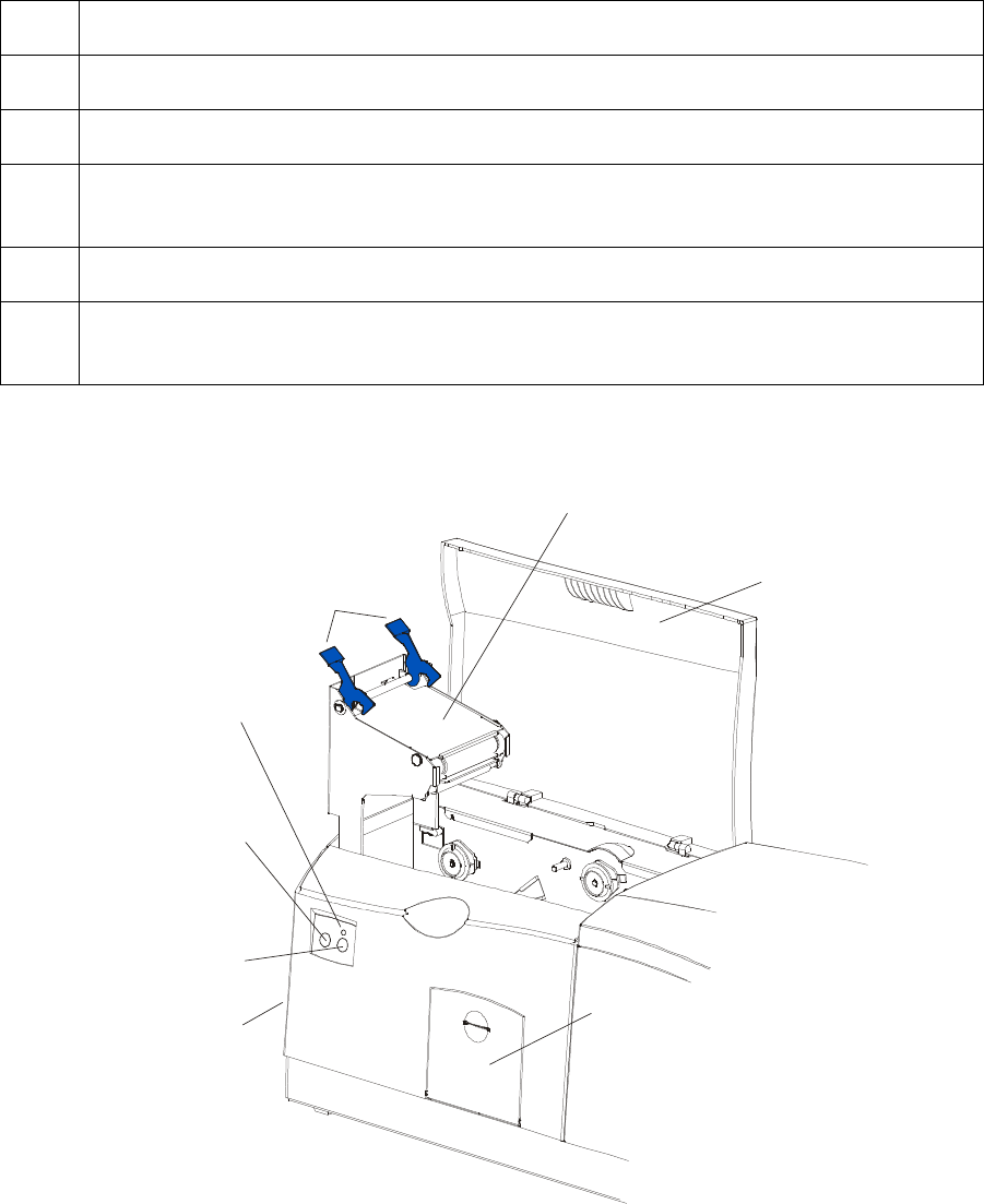
Lamination
Top Cover
Securing
Latches
Lamination Station
Lamination
LED Light
Cancel
Button
Resume
(pause) Button
Rejection
Card Hopper
Card Output
Hopper

RESTRICTED USE ONLY Fargo Electronics, Inc.
DTC550 Direct to Card Printer/Encoder User Guide (Rev. 1.0) 1-7
Reviewing the Lamination Module Sequence of Operations (continued)
Step
Process
6 The Card Feed Motor and the Lamination Ribbon Motor activate for the length of
the card.
7 The Lamination Roller Lift Motor cycles until Lamination Roller Lift Sensor detects
state change.
8 The card is fed back to the Flipper Table.
9 The Flipper Table Clutch engages.
10 The Flipper Table Motor activates until the Card is inverted based on the Flipper
offset setting.
11 The Flipper Table Clutch disengages.
12 The card is fed off the Flipper Table.
13 The Flipper Table Clutch engages.
14 The Flipper Table Motor activates until the Flipper Table is homed.
15 The Flipper Table Clutch disengages.
16 Repeat Steps 2 through 7.
17 The card is fed out of the Printer.

RESTRICTED USE ONLY Fargo Electronics, Inc.
DTC550 Direct to Card Printer/Encoder User Guide (Rev. 1.0) 1-8
Reviewing the Lamination Module Boot up Sequence
Step Process
1 The Lamination Headlift turns until head up position is returned from Headlift
Sensor.
2 The Lamination Ribbon motor activates to determine the presence of a roll of
lamination.
3 The Lamination Flipper table homes itself.
4 The Card sensor checks for the presence of a card and ejects it if found.

RESTRICTED USE ONLY Fargo Electronics, Inc.
DTC550 Direct to Card Printer/Encoder User Guide (Rev. 1.0) 2-1
Section 2: Specifications
The purpose of this section is to provide the User with specific information on the Regulatory
Compliances, Agency Listings, Technical Specifications and Functional Specifications for the
DTC550 Direct to Card Printer/Encoder User Guide (Rev. 1.0).
Regulatory Compliances
Term Description
CSA (cUL) The Printer manufacturer has been authorized by UL to represent the
Card Printer as CSA Certified under CSA Standard C22.2 (No. 60950-
1).
File Number: E145118
FCC The Card Printer complies with the requirements in Part 15 of the FCC
rules for a Class A digital device. (Note: These requirements are
designed to provide reasonable protection against harmful interference
in a commercial environment.)
EMC The Card Printer has been tested and complies with EN55022 Class A
and EN61000-3-2, EN61000-3-3 and EN55024.
(Note: Based on the above testing, the Printer manufacturer certifies
that the Card Printer complies with all current EMC directives of the
European Community and has placed the CE mark on the Card
Printer.)
UL The Card Printer is listed under UL IEC 60950-1 (2001) INFORMATION
TECHNOLOGY EQUIPMENT.
File Number: E145118

RESTRICTED USE ONLY Fargo Electronics, Inc.
DTC550 Direct to Card Printer/Encoder User Guide (Rev. 1.0) 2-2
Agency Listings
Term Description
EMC Standards CE, FCC, CRC c1374, EN 55022 Class A, FCC Class A, EN 55024,
EN61000-3-2 and EN61000-3-3.
Safety
Standards UL IEC 60950-1 (2001), CSA C22.2 No. 60950-1 and EN 60950-
1:2001.
FCC Rules
This device complies with Part 15 of the FCC rules. Operation is subject to the following two
conditions:
1. This device may not cause harmful interference.
2. This device must accept any interference received, including interference that may cause
undesired operation.
Note (see below):
This equipment has been tested and found to comply with the limits for a Class A digital
device, pursuant to part 15 of the FCC Rules. These limits are designed to provide
reasonable protection against harmful interference when the equipment is operated in a
commercial environment.
This equipment generates, uses, and can radiate radio frequency energy and, if not
installed and used in accordance with the instruction manual, may cause harmful
interference to radio communications.
Operation of this equipment in a residential area is likely to cause harmful interference in
which case the user will be required to correct the interference at his or her own expense.
Reference Safety Messages in this document.
RESTRICTED USE ONLY Fargo Electronics, Inc.
DTC550 Direct to Card Printer/Encoder User Guide (Rev. 1.0) 2-3
Safety Messages (review carefully)
Symbol Critical Instructions for Safety purposes
Danger:
Failure to follow these installation guidelines can result in death or
serious injury.
Information that raises potential safety issues is indicated by a warning
symbol (as shown to the below).
To prevent personal injury, refer to the following safety messages
before performing an operation preceded by this symbol.
To prevent personal injury, always remove the power cord prior to
performing repair procedures, unless otherwise specified.
To prevent personal injury, make sure only qualified personnel
perform these procedures.
Caution:
This device is electrostatically sensitive. It may be damaged if
exposed to static electricity discharges.
Information that raises potential electrostatic safety issues is indicated
by a warning symbol (as shown to the below).
To prevent equipment or media damage, refer to the following
safety messages before performing an operation preceded by this
symbol.
To prevent equipment or media damage, observe all established
Electrostatic Discharge (ESD) procedures while handling cables in
or near the Circuit Board and Printhead Assemblies.
To prevent equipment or media damage, always wear an
appropriate personal grounding device (e.g., a high quality wrist
strap grounded to avoid potential damage).
To prevent equipment or media damage, always remove the
Ribbon and Cards from the Printer before making any repairs,
unless otherwise specified.
To prevent equipment or media damage, take jewelry off of
fingers and hands, as well as thoroughly clean hands to remove oil
and debris before working on the Printer.

RESTRICTED USE ONLY Fargo Electronics, Inc.
DTC550 Direct to Card Printer/Encoder User Guide (Rev. 1.0) 2-4
Technical Specifications
Term Description
Accepted
Standard Card
Size
CR-79 Adhesive Back: 3.303 in. x 2.051 in. (83.9mm x 52.1mm)
(cannot be laminated with DTC550-LC)
CR-80: 3.375 in. x 2.125 in. (85.6mm x 54mm) (corresponds to ID1)
Accepted Card
Thickness .020 in. (20 mil) to .050 in. (50 mil) (.254mm to 1.27mm); unless
laminating.
Continued on the next page

RESTRICTED USE ONLY Fargo Electronics, Inc.
DTC550 Direct to Card Printer/Encoder User Guide (Rev. 1.0) 2-5
Technical Specifications (continued)
Term Description
Accepted Card
Types Prox (125 kHz): HID Proximity Cards (read only)
Contactless (13.56 MHz)
Gemplus GemEasyLink 332 (soon to be GemProx)
ISO 14443-A Mifare Cards (Mifare Ultra Light, Classic 1k / 4k, Pro
X) - Read/Write
ISO 14443-B Contactless Cards (T=CL), (and DESFire available
with GemProx next month???) - Read/Write
HID iClass (OEM 100 & 300)
ISO 15693 - Read/Write (iClass)
ISO 14443-A - read only (Mifare card serial number)
ISO 14443-B2 - Read/Write (iClass)
Contact
ISO 7816-1,2,3,4 contact cards (T=0, T=1 protocol)
Accepted Card
Compositions PVC or polyester cards with polished PVC finish; monochrome resin
required for 100% polyester cards.
Barcodes Code 39, Code 128 B & C with and without check digit (available with
embedded font and barcode option)
2 of 5
UPC-A
EAN 13
PDF-417 2D barcode and other symbologies (available via
Windows Driver)
Card Input
Hopper
Capacity
Dual-stack Hopper, 200 cards (30 mil); auto or manual feed
Card Output
Hopper
Capacity
100 cards (30 mil)
Continued on the next page

RESTRICTED USE ONLY Fargo Electronics, Inc.
DTC550 Direct to Card Printer/Encoder User Guide (Rev. 1.0) 2-6
Technical Specifications (continued)
Term Description
Card Cleaning Removable card cleaning cartridge with replaceable cleaning roller.
Colors Up to 16.7 million colors and 256 shades per pixel.
Dimensions DTC550: 10.75 in. H x 18.5 in. W x 11 in. D (273mm x 470mm x
279mmD).
DTC550-LC: 10.75 in. H x 30.5 in. W x 11 in. D (273mm x
775mm x 279mmD).
LC Module: 10.25” H x 30” W x 11”D/260mm H x 762mm W x
279mmD
Display SmartScreen LCD Control Panel; LED display on Card Lamination
Module.
Encoding Options ISO Magnetic Stripe Encoding Module; dual high- and low-coercivity;
Tracks 1, 2 and 3; and Super-hi-co (4000 Oe)
Contact Smart Card Encoder read from and writes to all ISO 7816-
1/2/3/4 memory and microprocessor card using the T=0 or T=1
protocol, as well as synchronous cards.
13.56 MHz Contactless Smart Card Encoders
Gemplus GemEasyLink 332 (soon to be GemProx)
ISO 14443-A Mifare Cards (Mifare Ultra Light, Classic 1k / 4k, Pro
X) - Read/Write
ISO 14443-B Contactless Cards (T=CL), (and DESFire available
with GemProx next month???) - Read/Write
HID iClass (OEM 100 & 300)
ISO 15693: Read/Write (iClass)
ISO 14443-A: Read only (Mifare card serial number)
ISO 14443-B: Read/Write (iClass)
125 kHz Prox Card Reader
HID read-only, 24-bit to 85-bit. Typical card is 26-bit format or 35-
bit Corporate 1000 format.
Continued on the next page

RESTRICTED USE ONLY Fargo Electronics, Inc.
DTC550 Direct to Card Printer/Encoder User Guide (Rev. 1.0) 2-7
Technical Specifications (continued)
Term Description
Fargo Certified
Supplies Fargo Card Printer/Encoder require highly specialized media to
function properly. To maximize printed card quality, printhead life and
Printer/encoder reliability, use only Fargo Certified Supplies. Fargo
warranties are void, where not prohibited by law, when non-Fargo
Certified Supplies are used.
Fonts TrueType fonts are available via the Windows driver.
Humidity 20% to 80% Non-Condensing.
Interface USB only for print
Memory 4 MB RAM
Options Printer Cleaning Kit
External Print Server (Windows only; required for stand-alone
networking of Printer/encoders)
Card Lamination Module
Operating
Temperature 65ºF to 80ºF (18ºC to 27ºC).
Overlaminate
Options (for LC) Thermal Transfer Overlaminate, .25 mil thick
PolyGuard Overlaminate, 1.0 mil and .6 mil thick
All overlaminates available in clear, holographic globe design or
custom holographic design
Print Area CR-80 edge-to-edge: (3.37 in. x 2.12 in./85.5mm x 53.5mm)
CR-79: (3.3 in. x 2.051 in./83.8mm x 52.1mm)
Printing Method Dye-Sublimation/Resin Thermal Transfer.
Printing
Resolution Up to 16.7 million colors and 256 shades per pixel.
300 dpi (11.8 dots/mm)
Continued on the next page

RESTRICTED USE ONLY Fargo Electronics, Inc.
DTC550 Direct to Card Printer/Encoder User Guide (Rev. 1.0) 2-8
Technical Specifications (continued)
Term Description
Print Speed –
Batch Mode
K: 7.0 seconds per card/514 cards per hour
BO: 12 seconds per card/300 cards per hour
YMCKO: 22 seconds per card/163 cards per hour
YMCKO: 30 seconds per card/120 cards per hour
YMCK (w/Lamination): 28 seconds per card/128 cards per hour
(see related note below)
YMCKK (w/Lamination): 35 seconds per card /102 cards per
hour
Indicates the Print Ribbon type and the number of Ribbon panels
printed where Y=Yellow, M=Magenta, C=Cyan, K=Resin Black,
B=Dye-Sublimation Black and O=Overlay.
Print speeds do not include the time needed for the PC to process
the image.
Process time is dependent on the size of the file, the CPU,
amount of RAM and the amount of available resources at the time
of the print.
Print speed indicates an approximate batch print speed and is
measured from the time a card feeds into the Printer to the time it
ejects from the Printer. (Note: The single card print speeds will
be slower than the batch print speeds listed above since batch
print speed is enhanced by the Printer's multi-tasking capabilities
when printing multiple cards in succession.)
Continued on the next page

RESTRICTED USE ONLY Fargo Electronics, Inc.
DTC550 Direct to Card Printer/Encoder User Guide (Rev. 1.0) 2-9
Technical Specifications (continued)
Term Description
Print Ribbon
options
YMCKO (500 image, with RFID)
YMCKOK (400 image, with RFID)
YMCKK (500 image, with RFID)
YMCFKO and YMCFKOK (SecureMark Ribbons)
Resin, Black Premium (3000 image, with RFID)
Resin, Black Standard (3000 image, with RFID)
Resin, Blue (1000 image, with RFID)
Resin, Green (1000 image, with RFID)
Resin, Red (1000 image, with RFID)
Resin, White (1000 image, with RFID)
Resin, Gold Metallic (500 image, with RFID)
Resin, Silver Metallic (500 image, with RFID)
Resin, with Overlaminate (KO) (1500 image, with RFID)
Security Features Card Hopper Lock (optional)
Software Drivers 2000/XP
Supply Voltage DTC550: 100-240 VAC, 1.2A
DTC550-LC: 100-240 VAC; Two Supplies (1.2A each)
Continued on the next page

RESTRICTED USE ONLY Fargo Electronics, Inc.
DTC550 Direct to Card Printer/Encoder User Guide (Rev. 1.0) 2-10
Technical Specifications (continued)
Term Description
Supply
Frequency 50 Hz/60 Hz.
System
Requirements Windows® 2000 with Service Pack 4, Windows® XP with Service
Pack 2 and Windows® Server 2003; x86 300 MHz computer with 64
MB of RAM or higher, 200 MB free hard disk space or higher, USB
1.1
Warranty Printer (One year); optional Extended Warranty Program (U.S. only)
Printhead (One year), unlimited pass with UltraCard Cards
Weight DTC550: 20 lbs. (9.1 kg.)
DTC550-LC: 39 lbs. (14.1 kg.)
LC Module: 19 lbs. (8.6 kg.)

RESTRICTED USE ONLY Fargo Electronics, Inc.
DTC550 Direct to Card Printer/Encoder User Guide (Rev. 1.0) 2-11
Functional Specifications
The Card Printer utilizes two different, yet closely related printing technologies to achieve its
direct-to-card print quality for Dye-Sublimation and resin thermal transfer. The Card Printer
will print from any IBM-PC® or compatible running Windows 2000 or Windows XP.
The following describes how each of these technologies works:
Function Description
Dye-
Sublimation Dye-Sublimation is the print method the Card Printer uses to produce
smooth, continuous-tone images that look photographic. (Note: This
process uses a dye-based Ribbon roll that is partitioned by a number of
consecutive color panels.)
Process Colors: The panels are grouped in a repeating Series of three
process colors - yellow, magenta and cyan (YMC), along the entire
length of the Print Ribbon.
Panels: The Printer always prints the yellow panel first, followed by the
magenta panel and the cyan panel.
Printhead: As the Print Ribbon passes beneath the Printhead, hundreds
of thermal elements within the Printhead heat the dyes on the Ribbon.
(Note: When these dyes are heated, they vaporize and diffuse into the
surface of the card. A separate pass is made for each of the three color
panels on the Ribbon.)
Color Shades: By combining the colors of each panel and by varying the
heat used to transfer these colors, it is possible to print up to 16.7
million different shades of color. (Note: This blends one color smoothly
into the next, producing photo-quality images with absolutely no dot
pattern.)
Dye-Diffusion Thermal Transfer: It is the process of heating a dye
suspended in a cellulous substrate until the dye can flow, diffusing into
the dye receptive surface of the card or InTM. This produces the image
in the surface of the card.
Continued on the next page

RESTRICTED USE ONLY Fargo Electronics, Inc.
DTC550 Direct to Card Printer/Encoder User Guide (Rev. 1.0) 2-12
Functional Specifications (continued)
Function Description
Resin
Thermal
Transfer
Resin Thermal Transfer is the print method the Printer uses to print sharp
black text and crisp bar codes that can be read by both infrared and visible-
light bar code scanners.
Like Dye-Sublimation, this process uses the same thermal Printhead to
transfer color to a card from a resin-only Print Ribbon or the resin black (K)
panel of a full color Print Ribbon.
The difference, however, is that solid dots of resin-based ink are
transferred and fused to the surface of the card. (Note: This produces very
durable, saturated printing.)
Continued on the next page
RESTRICTED USE ONLY Fargo Electronics, Inc.
DTC550 Direct to Card Printer/Encoder User Guide (Rev. 1.0) 2-13
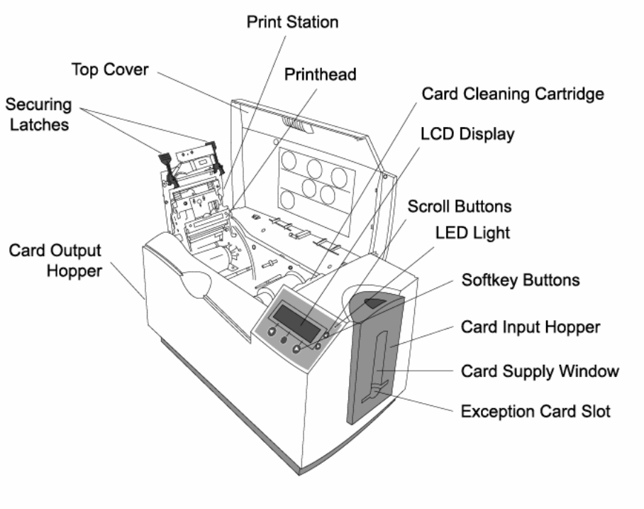
Printer Components - Descriptions
Component Description
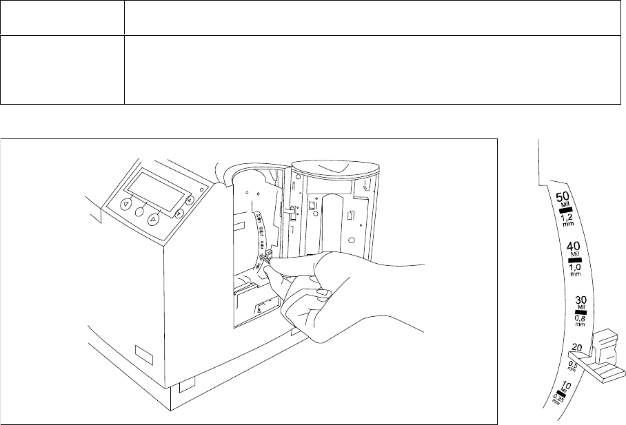
Card Thickness
Adjustment
Lever
Adjusts the Printer to feed varying card thicknesses.
RESTRICTED USE ONLY Fargo Electronics, Inc.
DTC550 Direct to Card Printer/Encoder User Guide (Rev. 1.0) 2-14
Printer Components: Descriptions (continued)
Component Description
Card Cleaning
Cartridge Automatically cleans cards for higher print quality. (Note: Replace this
roller with every ribbon or as needed.)
RESTRICTED USE ONLY Fargo Electronics, Inc.
DTC550 Direct to Card Printer/Encoder User Guide (Rev. 1.0) 2-15
Printer Components: Descriptions (continued)
Component Description
Card Input
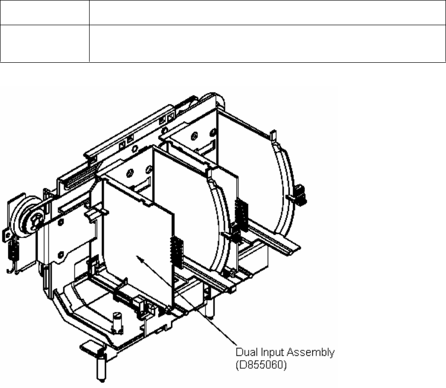
Hopper Load blank cards into this Dual Input Hopper.
RESTRICTED USE ONLY Fargo Electronics, Inc.
DTC550 Direct to Card Printer/Encoder User Guide (Rev. 1.0) 2-16
Printer Components: Descriptions (continued)
Component Description
Card Output
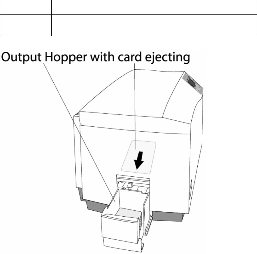
Hopper Stores printed cards; up to 100, 30 mil cards.

RESTRICTED USE ONLY Fargo Electronics, Inc.
DTC550 Direct to Card Printer/Encoder User Guide (Rev. 1.0) 2-17
Printer Components: Descriptions (continued)
Component Description
Card Supply
Window Check the current card supply at-a-glance, without having to open the
Card Hopper Door.
Card Input
Hopper Lock This lock allows you to lock the Card Input Hopper Door to help prevent
the theft of blank cards.
Exception Card
Slot Insert a single exception card into this slot if you would like to print onto
a card other than those loaded in the Card Input Hopper.
LCD display Displays the current status of the Printer.
LED light Indicates Printer ON, OFF, pause, status conditions and error
conditions.
Continued on the next page
RESTRICTED USE ONLY Fargo Electronics, Inc.
DTC550 Direct to Card Printer/Encoder User Guide (Rev. 1.0) 2-18
Printer Components: Descriptions (continued)
Component Description
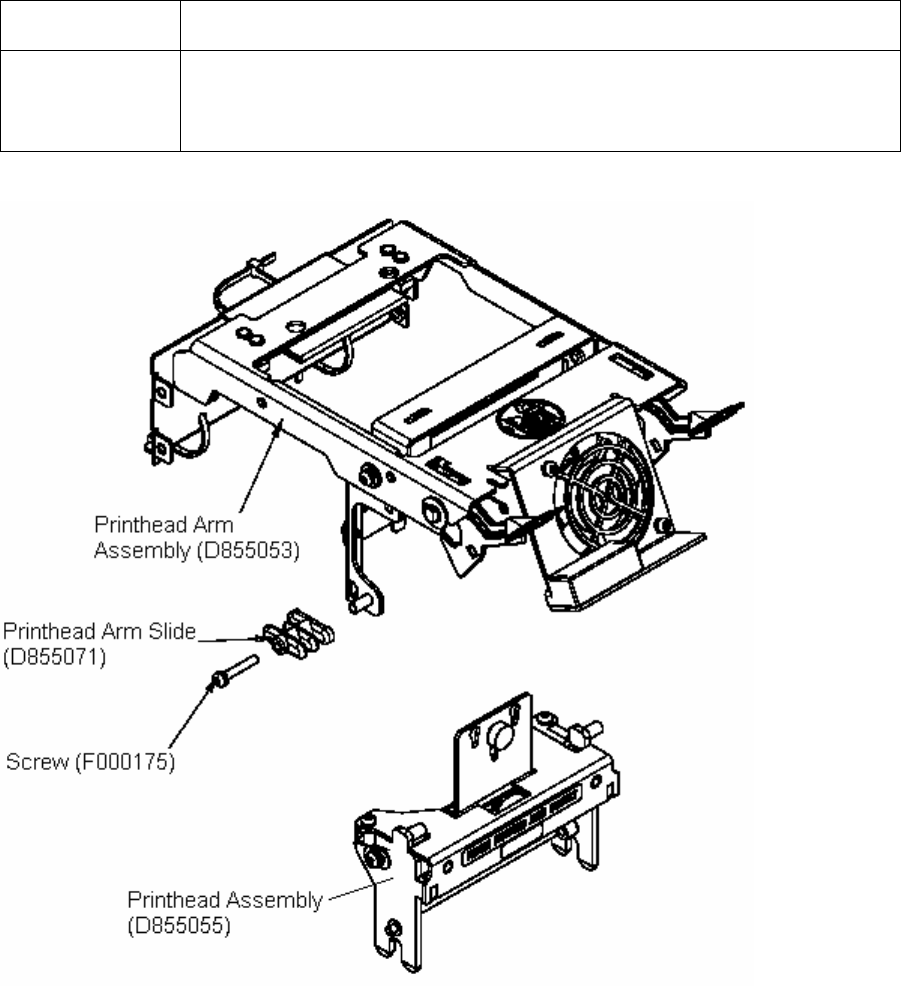
Printhead This Print Station component actually does the printing. (Note: This
component is fragile and must not be bumped or touched with anything
other than a cleaning pen.)

RESTRICTED USE ONLY Fargo Electronics, Inc.
DTC550 Direct to Card Printer/Encoder User Guide (Rev. 1.0) 2-19
Printer Components: Descriptions (continued)
Component Description
Power Switch This switch turns the Printer power ON and OFF.
Power Port This port connects to the (included) power supply.
Securing
Latches These latches lock the Print Station securely in place when closed.
Softkey Buttons The button function is displayed above the button. The buttons change
depending upon the Printer's mode of operation.
Scroll Buttons These buttons are used to scroll through menus and sub-menus and to
adjust certain menu options.
USB Interface
Port This port connects to a Windows PC with a parallel cable.
Serial Interface
Ports For Encoding option: These ports are provided only if your Printer
includes one or more optional Encoding Modules.
Continued on the next page
RESTRICTED USE ONLY Fargo Electronics, Inc.
DTC550 Direct to Card Printer/Encoder User Guide (Rev. 1.0) 2-20
Printer Components: Descriptions (continued)
Refer to the previous table.

RESTRICTED USE ONLY Fargo Electronics, Inc.
DTC550 Direct to Card Printer/Encoder User Guide (Rev. 1.0) 2-21
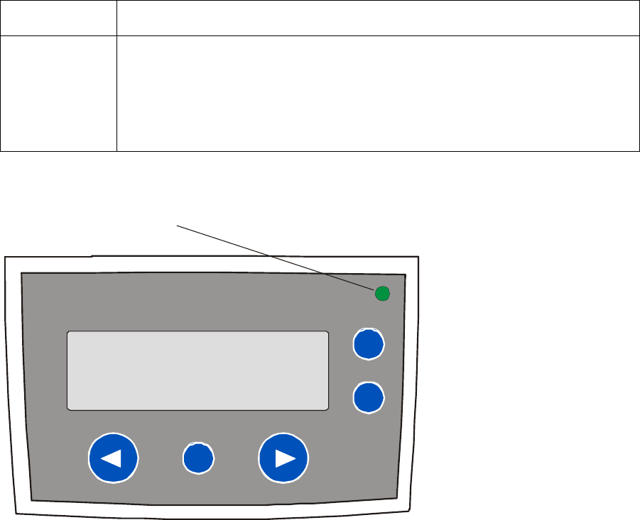
Printer Components: LCD and Softkey Control Pad
The Printer provides a four line, eighty (80) character LCD display that communicates helpful
information about the Printer's operation.
The top three lines of the LCD display will always be used to communicate print status,
error messages and menu options.
The bottom line of the LCD display will always be used to communicate the current
function of the Printer's softkey buttons.
This section describes how the LCD display and Softkey Control Pad work together.
Component Description
Softkey
Buttons The Printer has three softkey buttons that appear below the LCD
display. (Note: Their current function is indicated by the words
appearing above them. This function will change according to the
Printer's current mode of operation.)
Press the corresponding softkey button for the correct selection.
(Note: If no word appears above a particular button, this indicates it
has no function in that particular mode of operation.)
Use the scroll buttons to scroll through help text, to navigate through
the Printer's menus and to adjust certain Printer settings. (Note: The
Printer has scroll buttons on its control pad located just to the right of
the LCD display.)
If scrolling through a list, this symbol will change to if you have
reached the bottom of the list or if you have reached the top.
LCD display The Printer's LCD display will change according to the Printer's current
mode of operation.
System Check
Screens When the Printer is first powered ON, the Printer's system check screens
will briefly appear to:
Initialize the system.
Display the READY screen and current Firmware version.
Continued on the next page

RESTRICTED USE ONLY Fargo Electronics, Inc.
DTC550 Direct to Card Printer/Encoder User Guide (Rev. 1.0) 2-22
Printer Components: LCD and Softkey Control Pad (continued)
Component Description
Ready/Printer
Open Screens
Once the Printer has finished its system check and with the Print and
Transfer Stations closed, the Printer will display READY to indicate that
the Printer is ready for operation. (Note: The Printer will stay in this
mode until it receives a print job or it is turned OFF.)
If the Top cover and Printhead Arm are opened, the Printer Open screen
will appear.
Press either the Forward or Back buttons to move the Printer's card
path Rollers in the indicated direction.
In any of these screens, the Printer will always display the Menu option
above the center softkey button.
Press this button to access the Printer's menu options. (Note: The
Menu option is available only in the Ready/Printer Open screens.)
Print Status
Screen During operation, the LCD will indicate the current Print Status by
showing you the area of the Printer that is active. It does this by
displaying the following icons on the second line:
FEEDING indicates the Feeder Station is feeding a blank card into
the Printer.
ENCODING indicates the Encode Station is encoding a card
(appears only if you are using a Printer with an optional built-in
Encoding Module).
PRINTING indicates the Print Station is printing onto the card.
LAMINATING indicates the Lamination Station is applying an
overlaminate to a card (appears only if using a Printer equipped with
the optional Card Lamination Module. See Card Lamination Module.
Since the Printer is capable of performing several of these functions
simultaneously, one or all of these icons may appear at once, depending
on if you are printing just one card or a batch of cards.
The Print Status screen always displays Cancel in the lower left and
Pause in the lower right.
Continued on the next page

RESTRICTED USE ONLY Fargo Electronics, Inc.
DTC550 Direct to Card Printer/Encoder User Guide (Rev. 1.0) 2-23
Printer Components: LCD and Softkey Control Pad (continued)
Component Description
The Cancel
button Use this button to cancel print jobs and reset the Printer for the next print
job.
This Cancel function will ask if you wish to cancel just the individual
job or all jobs in the queue. You may also resume the current job by
pressing NO.
Pause button Use this button to pause the Printer at any time during operation. (Note:
The Printer will always finish its current task before pausing. When the
Printer is paused, the LED light will flash and the Pause softkey button
will change to Resume.)
Press Resume to continue Printer operation.
Continued on the next page
RESTRICTED USE ONLY Fargo Electronics, Inc.
DTC550 Direct to Card Printer/Encoder User Guide (Rev. 1.0) 2-24
Printer Components: LCD and Softkey Control Pad (continued)
Component Description
LED light This light works in conjunction with the Printer's LCD display to help
communicate the Printer's current status. (Note: It is especially effective
when the User is too far away from the Printer to read the LCD display.)
See the descriptions for Error Screens and Attention Screens after this
LED Light display for more detail on the Printer's LCD display.
Continued on the next page
LED Light

RESTRICTED USE ONLY Fargo Electronics, Inc.
DTC550 Direct to Card Printer/Encoder User Guide (Rev. 1.0) 2-25
Printer Components: LCD and Softkey Control Pad (continued)
Component Description
Error Screens
(see previous
section)
Your Printer is capable of communicating two similar yet different types
of message screens:
The first is called an ERROR screen. This screen appears if an error
occurs and will completely stop Printer operation.
In this case, the LCD will display ERROR on the first line and a brief
description of the error on the second line.
If multiple errors occur at the same time, the first line will display
ERROR 1 of 2 or whatever the total number of errors may be.
To see the other error(s), use the scroll keys.
Press the HELP button to bring up the help screen explaining the
nature of the error and how to correct it. If necessary, use the scroll
buttons to scroll down the paragraph of help text.
Press QUIT when you are done reading. Once the error is corrected,
resume operation or reset the Printer according to how you were
instructed in the help screen.
Attention
Screens (see
previous
section)
The second type of prompt is called an ATTENTION screen.
This screen will not stop Printer operation and serves to communicate
helpful reminder (e.g., when running low on print supplies).
This screen communicates any other Printer conditions of which you
should be aware.
In this case, the LCD will display ATTENTION on the first line and a brief
description of the condition on the second line.
If multiple messages need to be communicated at the same time, the
first line will display ATTENTION 1 of 2 or whatever the total number
of messages may be.
Like error messages, help text explaining the particular condition can
also be accessed by pressing the HELP button.

RESTRICTED USE ONLY Fargo Electronics, Inc.
DTC550 Direct to Card Printer/Encoder User Guide (Rev. 1.0) 2-26
Printer Components: Print Ribbons
The Card Printer utilizes both Dye-Sublimation and/or resin thermal transfer methods to print
images directly onto blank cards. Since the Dye-Sublimation and the resin thermal transfer
print methods (each) provide their own unique benefits, Print Ribbons are available in resin-
only, Dye-Sublimation-only and combination Dye-Sublimation/resin versions.
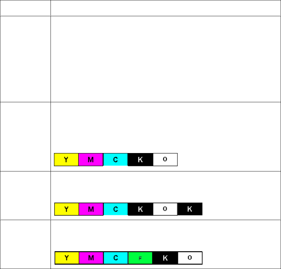
This letter code indicates the type of Ribbon panel used with each Ribbon.
= Dye-Sublimation Yellow Panel
= Dye-Sublimation Magenta Panel
= Dye-Sublimation Cyan Panel
= Resin Black Panel
= Overlay Panel
= Overlay Panel

RESTRICTED USE ONLY Fargo Electronics, Inc.
DTC550 Direct to Card Printer/Encoder User Guide (Rev. 1.0) 2-27
Printer Components: Resin-Only Print Ribbons
Resin-only Print Ribbons consist of a continuous roll of a single resin color. No protective
overlay panel (O) is provided since resin images do not require the protection of such an
overlay..
Type Description
Standard Resin Black
(K) (provides 3,000
prints)
This Ribbon provides high resin durability ideal for most
general-purpose monochrome ID card applications. Resin black
bar codes are readable by both infrared and visible-light bar
codes scanners.
Premium Resin Black
(K) (provides 3,000
prints)
This Ribbon provides maximum resin durability ideal for
applications such as access control where cards are repeatedly
swiped through a Magnetic Stripe reader. Resin black bar codes
are readable by both infrared and visible-light bar codes
scanners.
(Note: Using a Premium Resin Black Ribbon will provide better
photo realistic output.)
Colored Resin
(provides 1,000 prints)
Several colored resin Ribbons are available in a variety of colors
for customizing or color-coding resin-only ID cards.
Metallic Resin
(provides 500 prints)
Metallic resin Ribbons are available for printing resin images
with a unique metallic sheen.

RESTRICTED USE ONLY Fargo Electronics, Inc.
DTC550 Direct to Card Printer/Encoder User Guide (Rev. 1.0) 2-28
Printer Components: Dye-Sublimation Print Ribbons
Note that the Printer requires both specialized and authorized Print Ribbons in order to print
and function properly.
Step Procedure
1 Do not run the cards with a contaminated, dull or uneven surface through the
Printer.
Caution: Printing onto such cards will ultimately lead to poor print
quality and will greatly reduce the life of the Printhead.
2 Always store the card stock in its original packaging or in a clean, dust-free
container.
3 Do not print onto cards that have been dropped or soiled. (Note: Printhead
damage caused by contaminated or poor quality cards will automatically void the
Printhead's factory warranty.)
4 If printing onto cards with a pre-punched slot, do not print over the area of the
card with the punched slot. (Note: To avoid this area when printing, use the
options in the Overlay / Print Area tab to omit printing in this area or punch the
slot after the card has printed.)
RESTRICTED USE ONLY Fargo Electronics, Inc.
DTC550 Direct to Card Printer/Encoder User Guide (Rev. 1.0) 2-29
Printer Components: Dye-Sublimation/Resin Print Ribbons
Type Description
Dye-
Sublimation/
resin Print
Ribbon
The Dye-Sublimation/resin Print Ribbon combines the yellow (Y),
magenta (M) and cyan (C) dye-sublimation panels with a resin black (K)
panel.
By combining both types of Ribbon panels, this Ribbon can be used to
print full-color, photo-quality images with the dye-sublimation panels
along with sharp, black text and bar codes with the resin black panel.
A clear overlay panel (O) is also included on most Ribbons to protect the
dye-sublimation images. Dye-Sublimation images must have an overlay
panel applied to them or they will quickly begin to wear or fade.
Full-Color
(YMCKO)
This Ribbon is used to print full-color photo ID cards along with resin
black text and bar codes. Both infrared and visible-light bar code
scanners can read bar codes printed with resin black.
An overlay panel (O) is included to protect the full-color dye-
sublimation printing.
YMCKOK The designation of colored Ribbon by the Panels of color in the order in
which they are printed: Yellow (Y), Magenta (M), Cyan (C), Black (K),
Overlay (O), Black (K) (used for backside, black only printing).
YMCFKO The designation of colored Ribbon by the Panels of color in the order in
which they are printed: Yellow (Y), Magenta (M), Cyan (C), Flourescent
(F), Black (K), Overlay (O), (used for backside, black only printing).

RESTRICTED USE ONLY Fargo Electronics, Inc.
DTC550 Direct to Card Printer/Encoder User Guide (Rev. 1.0) 2-30
Printer Components: Blank Cards
Caution: Never run cards with a contaminated, dull or uneven surface through the
Printer. Printing cards on this surface can lead to poor print quality and can greatly reduce
the life of the Printhead. Always store the card stock in its original packaging or in a clean,
dust-free container. Do not print onto cards that have been dropped or soiled. Printhead
damage caused by contaminated or poor quality cards will automatically void the Printhead's
factory warranty.
Type Description
Card Size The Card Printer accepts the following:
CR-79 sized cards (3.303” L x 2.051” W/83.9mm L x 52.1mm W) with a
thickness of 20 mil to 50 mil
OR
CR-80 sized cards (3.375” L x 2.125” W/85.6mm L x 54mm W; with a
thickness of 20 mil. to 50 mil.).
This does not apply for the LC Printers.
Card
Design The Printer will print onto any card with a clean, level and polished PVC
surface. (Note: Although the Printer is equipped with card cleaning Rollers,
it is very important to always print onto cards specifically designed for direct-
to-card Dye-Sublimation printing.)
Card
Surface Suitable cards must have a polished PVC surface free of fingerprints, dust or
any other types of embedded contaminants.
Cards must have a completely smooth, level surface in order for the Printer
to achieve consistent color coverage.
Some types of Proximity cards, for example, have an uneven surface which
will inhibit consistent color transfer.
Some Smart Card chips are raised slightly above the cards surface, which
also results in poor color transfer.

RESTRICTED USE ONLY Fargo Electronics, Inc.
DTC550 Direct to Card Printer/Encoder User Guide (Rev. 1.0) 2-31
Printer Components: Blank Cards (continued)
Type Description
UltraCard
Stock Due to the importance of using high-quality blank cards, a factory-approved
card stock called UltraCard™ is available and recommended for best results.
UltraCard stock has a glossy PVC laminate on top and bottom and is
optically inspected to provide the cleanest, most scratch and debris-
reduced cards possible.
Two types of these cards are available: UltraCard and UltraCard III.
UltraCard stock has a PVC core and offers medium card durability.
UltraCard III stock has a 40% polyester core and offers high durability.
Both types of UltraCards produce printed images with a glossy, photo-quality
finish.
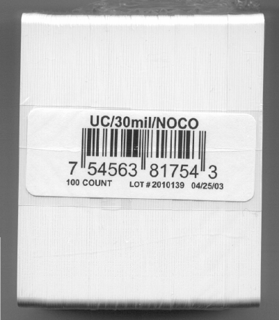
RESTRICTED USE ONLY Fargo Electronics, Inc.
DTC550 Direct to Card Printer/Encoder User Guide (Rev. 1.0) 2-32
Printer Components: Upgraded 81754 PVC Cards
The upgraded 81754 PVC cards are designed for a sharper card image quality and for
reduced debris and defects on Fargo Card Printers. Carefully read these detailed notes and
instructions before applying this information to your Fargo Printer or Printers.
Technician Note 1: The new card lot number starts at Lot # 2010104 with date codes
that started on 04/01/2003. The photo (below) shows a lot number that starts after Lot #
2010104, indicating a new card lot number. The card lot number and date can be read
on the bar code label attached to the shrink-wrapped stack of 100 cards, as shown
below. All new Fargo Printers with a serial number (S/N) starting with A320 will have
factory settings for these new 81754 PVC cards.
Technician Note 2: Do not use the new 81754 PVC card stock with Fargo laminating
Printers/encoders. This same guideline is used for the existing 81754 PVC card stock. Fargo
recommends using the UltraCard III stock with the Fargo laminating Printers/encoders.

RESTRICTED USE ONLY Fargo Electronics, Inc.
DTC550 Direct to Card Printer/Encoder User Guide (Rev. 1.0) 2-33
Reviewing the upgraded 81754 PVC Cards (continued)
Follow these two (2) instructions below:
1. Instruction for new 81754 PVC card stock: Increase the Printer Driver’s Dye-Sub
Intensity to print with the new 81754 PVC card stock on Fargo Card Printers (S/N A319
and older). See the chart provided below. See the appropriate Fargo service documents
for specific Printer Driver instructions.
Card New Printer (S/N A320 and
newer) Old Printer (S/N A319 and
older)
New Card No Change Necessary Increase the Dye-Sub Intensity as
follows:
DTC550: 5 - 10 %
2. Instruction for existing 81754 PVC card stock: The Printer Driver’s Dye-Sub Intensity
setting may or may not need to be decreased to print existing card stock. See the chart
provided below. See the appropriate Fargo service documents for specific Printer Driver
instructions.
Technician Note 1: To control the brightness of the image, adjust the Dye-Sub
Intensity slide on the Image Color tab of the Printer Driver.
Technician Note 2: Moving the Dye-Sub Intensity slide to the left causes less heat
to be used in the printing process, thus generating a lighter print.
Card New Printer (S/N A320 and
newer) Old Printer (S/N A319 and older)
Old Card Decrease the Dye-Sub Intensity
as follows:
DTC550: 5 - 10 %
No Change Necessary
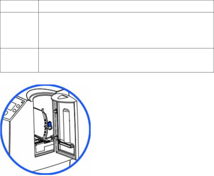
RESTRICTED USE ONLY Fargo Electronics, Inc.
DTC550 Direct to Card Printer/Encoder User Guide (Rev. 1.0) 2-34
Printer Components: Card Input and Output Hoppers
Type Description
Card Input
Hopper The Card Input Hopper is where cards are initially loaded for printing, as
shown below. The Printer's Hopper provides a large door that opens up
wide to make card loading simple and closes securely to help protect the
card stock. (Note: The Printer will hold a maximum of 100 cards in each
Card Input Hopper, based on a standard 30 mil. card thickness.)
Card Output
Hopper All standard Card Printers provide a 100 card capacity Card Output
Hopper (based on a standard 30 mil card thickness). (Note: This Hopper
stores the cards after they are printed.)
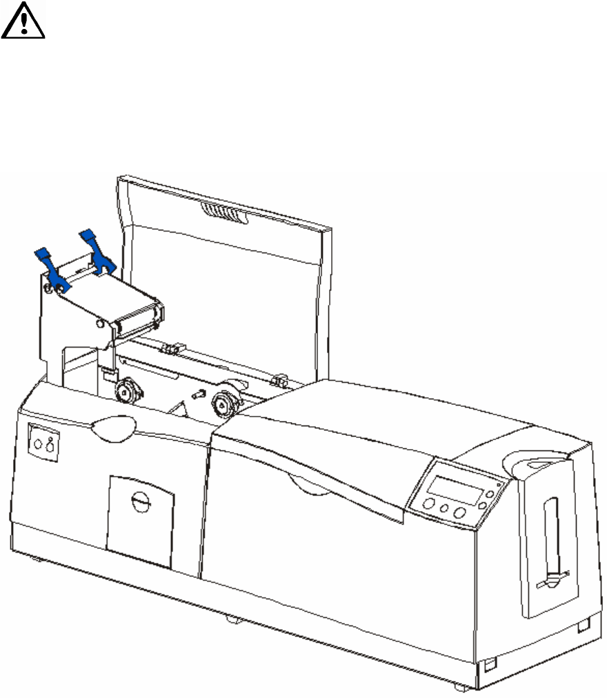
RESTRICTED USE ONLY Fargo Electronics, Inc.
DTC550 Direct to Card Printer/Encoder User Guide (Rev. 1.0) 2-35
Reviewing the Card Lamination Module
Danger: The Printer’s Lamination Roller can reach temperatures exceeding 350° F
(175° C). Use extreme caution when operating the Laminator. Never touch the Lamination
Roller unless the Printer has been turned off for at least 20 to 30 minutes.
Select Printer models support the attachment of an optional Card Lamination Module. This
module can be ordered pre-installed on your Printer from the factory or can be ordered
separately as a field upgradeable module.
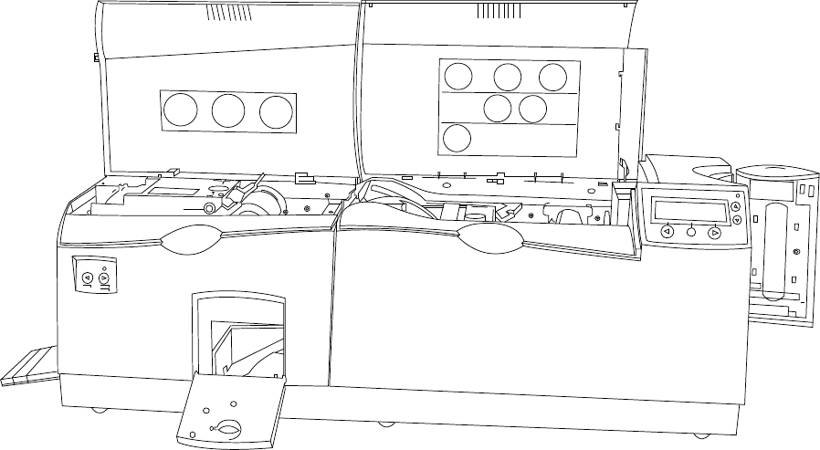
RESTRICTED USE ONLY Fargo Electronics, Inc.
DTC550 Direct to Card Printer/Encoder User Guide (Rev. 1.0) 2-36
Reviewing the Card Lamination Module (continued)
Here is another display of the Card Lamination Module.
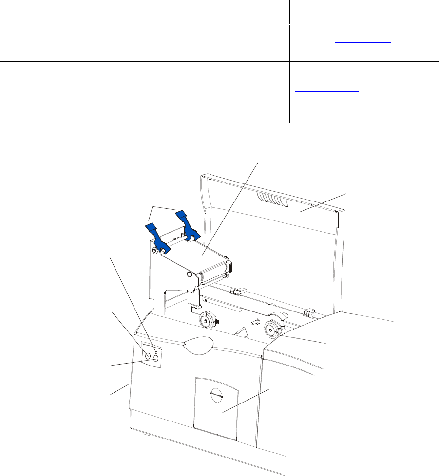
RESTRICTED USE ONLY Fargo Electronics, Inc.
DTC550 Direct to Card Printer/Encoder User Guide (Rev. 1.0) 2-37
Reviewing the Lamination Top Cover and Station
Component Description Cross Reference
Lamination
Top Cover Opens to allow access to the Lamination
Station, overlaminate and card path. See the Loading the
Overlaminate procedure.
Lamination
Station Transfers overlaminates onto cards via its
heated lamination Roller. The Lamination
Station must be closed in order for the
Printer to begin laminating.
See the Loading the
Overlaminate.
Lamination
Top Cover
Securing
Latches
Lamination Station
Lamination
LED Light
Cancel
Button
Resume
(pause) Button
Rejection
Card Hopper
Card Output
Hopper

RESTRICTED USE ONLY Fargo Electronics, Inc.
DTC550 Direct to Card Printer/Encoder User Guide (Rev. 1.0) 2-38
Reviewing the Securing Latches and Lamination LED light
Component Description Cross Reference
Securing
Latches Locks the Lamination Station securely in
place when closed. See the Using the
Lamination tab (only with
Card Lamination Module)
procedure.
Lamination
LED light The Lamination LED light works in
conjunction with the Printer's LCD display to
help communicate the Printer's current
status. The following explains how to
interpret the LED light.
Off: Indicates the Printer and
Lamination Module power is OFF.
Solid Green light: Indicates the Card
Lamination Module is ready for
operation.
Slow Flashing Green light: Indicates
the Lamination Module's (pause)
button was pushed and that the
Lamination Module is paused. This also
occurs when the Lamination Station is
open.
Fast Flashing Green light: Indicates
the Lamination Module is in need of
attention due to an error or an error
condition. Refer to the Printer's LCD
display for information.
See the Troubleshooting the
LCD Messages section.

RESTRICTED USE ONLY Fargo Electronics, Inc.
DTC550 Direct to Card Printer/Encoder User Guide (Rev. 1.0) 2-39
Reviewing the Cancel button
Component Description Cross Reference
Cancel
Button The Cancel button serves to cancel the
current lamination job and reset the Card
Lamination Module for the next lamination
job.
If a card is left within the Lamination
Module after a print job is canceled, it will
automatically be ejected into the
Rejection Card Hopper. (Note: With the
Lamination Module's Transfer Station
open, this button can also be used to
manually rotate the Feed Rollers
forward. This is helpful when cleaning
the Rollers or if clearing jammed media.)
If you are printing and laminating
simultaneously and you would like to
cancel both the print and lamination jobs,
press the Printer's CANCEL softkey
button. (Note: This will cancel all jobs in
the Printer. Any card currently laminating
will finish and eject. The Lamination
Module's Cancel button cancels only the
lamination job.)
See Card Lamination
Module.
Continued on the next page

RESTRICTED USE ONLY Fargo Electronics, Inc.
DTC550 Direct to Card Printer/Encoder User Guide (Rev. 1.0) 2-40
Reviewing the Resume (pause) button
Component Description Cross Reference
Resume
(pause)
button
Press the Resume button to resume
operation after an error condition is
cleared.
If an error occurs, the Lamination
Module's LED will flash and the
Printer's LCD will report the specific
error.
If this happens, correct the error and
press the Lamination Module's
Resume button to continue printing.
Press this button to pause the
Lamination Module during normal
operation. (Note: The Lamination
Module will always finish its current task
before pausing.)
If this button is pressed while a card
is being laminated, the Lamination
Module will pause only after the
current card has finished laminating
and the Lamination Module has
reached a safe stopping point.)
If the Printer is paused, the LED
light will flash slowly and will return
to solid when operation is resumed.
(Note: with the Lamination Station
open, the Resume button can also
be used to manually rotate the Feed
Rollers backward. This is helpful
when cleaning the Rollers or when
clearing jammed media.)
See the Using the Lamination
tab (only with Card Lamination
Module) procedure.

RESTRICTED USE ONLY Fargo Electronics, Inc.
DTC550 Direct to Card Printer/Encoder User Guide (Rev. 1.0) 2-41
Reviewing the Rejection Card Hopper and Card Output Hopper
Component Description Cross Reference
Rejection
Card Hopper The Rejection Card Hopper helps to
separate potentially bad cards from a stack
of good cards, which it ejects into the Card
Output Hopper.
The Printer will automatically eject cards
into this Hopper to indicate:
There is a printing error, laminating
error or encoding error.
There is a card is left in the Printer after
a print job is canceled or the Printer
restarted.
See the Using the
Lamination tab (only with
Card Lamination Module)
procedure.
Card Output
Hopper Stores up to 100 printed cards (30 mil
cards).
a. When the Hopper has reached its
maximum capacity of cards, note that
the operation pauses and an Output
Hopper Full message appears on the
Printer's LCD display.
b. Remove the stack of cards from the
Hopper.
c. Press the Lamination Module's Resume
button to continue. (Note: If printing
onto oversized cards, the Card Output
Hopper Door should be placed in the
open position in order for these larger
cards to eject properly.)
See the Using the
Lamination tab (only with
Card Lamination Module)
procedure.

RESTRICTED USE ONLY Fargo Electronics, Inc.
DTC550 Direct to Card Printer/Encoder User Guide (Rev. 1.0) 2-42
Reviewing the Module and Printer interaction
Term Description Cross Reference
Module
and
Printer
interaction
The Card Lamination Module works in
conjunction with the Printer to apply a
variety of different overlaminates to
printed cards, providing increased card
durability and security.
The Lamination Module features its own
LED indicator light and control buttons so
it can conveniently be operated separately
from the Printer. (Note: This means that
when printing a batch of cards, for
example, the Printer can be encoding and
printing one card while the Lamination
Module laminates another card for
maximum efficiency.)
In fact, you can even open the Lamination
Module to replace the overlaminate while
the Printer is printing or encoding and vice
versa.
See the Using the Lamination
tab (only with Card Lamination
Module) procedure.

RESTRICTED USE ONLY Fargo Electronics, Inc.
DTC550 Direct to Card Printer/Encoder User Guide (Rev. 1.0) 2-43
Reviewing the Module and LCD display interaction
Term Description Cross Reference
Module
and LCD
display
interaction
For ease of operation, the Card
Lamination Module works in tandem with
the Printer's LCD display to communicate
status message such as when an error
occurs or when it is time to replace the
overlaminate material.
If a lamination error does occur, the
Lamination Module's LED will flash and
an attention level message will appear on
the Printer's LCD display. (Note: Since it
is an ATTENTION level message, it will
not interrupt printing.)
a. Correct the error.
b. Press OK to clear the LCD's
ATTENTION message.
c. Press the Lamination Module's
Resume button to resume operation
or its Cancel button to cancel the
current lamination job and accept the
next. (Note: If canceled, the canceled
card will eject into the Rejection Card
Hopper.)
See the Using the Lamination
tab (only with Card Lamination
Module) procedure.
Continued on the next page

RESTRICTED USE ONLY Fargo Electronics, Inc.
DTC550 Direct to Card Printer/Encoder User Guide (Rev. 1.0) 2-44
Reviewing the Module’s Programmed Default Temperature
Term Description Reference
Programmed
Default
Temperature
Upon initial power up, the Lamination
Module is programmed to heat the
Lamination Roller up to its default
temperature.
Target Temperature: If a print job is
sent while the Lamination Module is
heating up, the Printer's LCD display
will read Laminator Warming. This will
alternate with LAM Temp: [current]
[target] which shows the current
temperature of the Lamination Roller
and the target temperature it is trying
to reach. (Note: This indicates that
the lamination Roller is heating to its
preset temperature.)
Initial Heating Process: The initial
heating process will generally take
about 3 to 4 minutes. (Note: The
LCD display will read Laminator
Warming or Laminator Cooling
whenever the Lamination Roller is
heating up or cooling down to the
prescribed temperature. When the
Lamination Module has reached its
target temperature, lamination will
begin.)
See the Using the Lamination
tab (only with Card Lamination
Module) procedure.

RESTRICTED USE ONLY Fargo Electronics, Inc.
DTC550 Direct to Card Printer/Encoder User Guide (Rev. 1.0) 2-45
Reviewing the Laminator Temperature Adjustment
Term Description
Laminator
Temperature
Adjustment
To change the temperature of the
Laminator, adjust its temperature through
the Lamination tab within the Printer
Driver setup window.
New Temperature Settings: Once
adjusted, the new temperature
settings will be sent down with the
next print job along with the rest of the
Printer Driver information. Before
printing begins, the laminator will
automatically adjust itself to the new
temperature setting. (Note: This new
temperature setting will remain
programmed within the Printer until it
is once again changed within the
Printer Driver or until the Printer is
turned OFF.)
Automatic Reset: Whenever the
Printer is turned OFF, the laminator
will automatically reset itself and
return to its default temperature the
next time the Printer is turned ON.
(Note: Pressing the Lamination
Module's or Printer's Cancel button or
switching the Printer power OFF and
ON both serve to reset the Laminator
to its default temperature.)
Consistent Temperature: The
temperature setting within the Printer
Driver stays the same until it is
changed.
See the Using the Lamination
tab (only with Card Lamination
Module) procedure.

RESTRICTED USE ONLY Fargo Electronics, Inc.
DTC550 Direct to Card Printer/Encoder User Guide (Rev. 1.0) 2-46
Reviewing the Overlaminates
IMPORTANT! Fargo Card Printers require highly specialized overlaminates to function
properly. To maximize Printer life, reliability, printed card quality and durability, you must use
only Fargo Certified Supplies. For this reason, the Fargo warranty is void, where not
prohibited by law, if you use non-Fargo Certified Supplies. To order additional materials,
please contact the authorized reseller.
Reviewing the Thermal Transfer Film and PolyGuard Overlaminates
Term Description Cross Reference
Thermal
Transfer Film
and
PolyGuard
Overlaminates
The Card Lamination Module will accept
either a Thermal Transfer Film overlaminate
or a polyester patch overlaminate called
PolyGuard™.
Thermal Transfer Film: The Thermal
Transfer Film overlaminate is a relatively
thin material which covers a card edge-
to-edge and provides a medium level of
card durability and security.)
PolyGuard overlaminate: PolyGuard
is a much thicker material which does
not cover edge-to-edge, but provides an
extremely high level of card durability
and security. (Note: PolyGuard is
available in either a 1.0 or .6 mil
thickness and should always be used for
those applications requiring the highest
degree of card durability and security.)
See the Loading the
Overlaminate procedure.

RESTRICTED USE ONLY Fargo Electronics, Inc.
DTC550 Direct to Card Printer/Encoder User Guide (Rev. 1.0) 2-47
Reviewing the CR-90 or CR-100 Patch Size
Term Description Cross Reference
CR-90 or
CR-100 PolyGuard overlaminate is available in a
standard CR-80 patch size as well as a CR-
90 and CR-100 patch size for laminating
oversized CR-90 or CR-100 cards. (Note:
Thermal Transfer Film overlaminate will
accommodate CR-80 and CR-90 card sizes,
but is not recommended for CR-100 cards.)
See the Loading the
Overlaminate procedure.
Reviewing the Overlaminate Design
Term Description Cross Reference
Design Both PolyGuard and the Thermal Transfer
Film overlaminates are available in either a
clear or generic secure holographic-type
design. (Note: Custom holographic-type
overlaminates are also available with specific
designs, patterns, logos and security
features.)
Please contact the authorized reseller for
more information about custom
Overlaminates.
See the Loading the
Overlaminate procedure.
RESTRICTED USE ONLY Fargo Electronics, Inc.
DTC550 Direct to Card Printer/Encoder User Guide (Rev. 1.0) 2-48
Reviewing the Visual Security Solutions
VeriMarkTM Cards - 2-D holographic foil application
VeriMarkTM Cards are a low cost, customized 2-D holographic foil application, that is made
in two steps.
The first step is to emboss a base foil 1.9 cm (L) x 1.3 cm (H) onto the surface of a blank
white card.
The second step is debossing a custom made dye into the surface of the base foil -
leaving a customized image, logo or text provided by the customer.
Two separate color foils are used to contrast the impression.
End Users will be able to choose between 8 different card placements (4 - landscape) and
(4-portrait) where the VeriMarkTM can be located. When its time to print through the driver,
the End User will select the location on their organizations card design around which no
printing and overlay will be placed.
Custom HoloMarkTM Cards
A Custom HoloMark TM Card is a three-dimensional holographic image transferred to metal
foil and embossed to blank cards. The image is customer specific and the program mirrors
our holographic laminates program with a couple exceptions.
Visual Security - Card Stock Part Numbers
All Visual Security Cards will be offered on the following Fargo Card Stocks only:
P/N# 81754 Ultra Card
P/N# 81762 Ultra Card III with hi-coercivity magnetic stripe
P/N# 81763 Ultra Card III
Visual Security - Fargo Certified Overlaminates (Special Order in 50
quantity minimum)
Part No. 82255: PolyGuard 1.0 mil for HoloMarkTM and VeriMarkTM Cards, Clear
Part No. 82256: PolyGuard 1.0 mil for HoloMarkTM and VeriMarkTM Cards, High
Resolution Globe design hologram with "Secure" micro-text
RESTRICTED USE ONLY Fargo Electronics, Inc.
DTC550 Direct to Card Printer/Encoder User Guide (Rev. 1.0) 3-49
Visual Security Card Stock - Tolerances
Tolerance of base foil placement will equal +/- .010" from the nearest edges of the card
Tolerance of layered foil will equal +/- .010"
VeriMarkTM - Application Specifications
VeriMarkTM foils will cover a dimensional area of 1.9 cm length x 1.3 cm height. The
exclusive areas are as follows:
VeriMarkTM Card customers will be able to choose 1 of 8 pre-defined placements
(corners) via Printer driver (4 positions) Landscape and (4 Positions) Portrait mode.
VeriMarkTM foil placement will not interfere with card punch slots .
Foil color base is silver; debossed impression is gold foil.
VeriMarkTM foil placement will be located 0.4 cm from the edges of the card except for
the top two locations on portrait orientation cards (positions E & F). The foil will be
located 0.9 cm from the top of the card and 0.4 cm from the sides of the card.
HoloMarkTM and Custom HoloMarkTM - Application Specifications
HoloMarkTM and Custom HoloMarkTM foils will cover a dimensional area of 1.5 cm x 1.5
cm. The exclusive areas are as follows:
HoloMarkTM and Custom HoloMarkTM card end-users will be able to choose 1 of 8 pre-
defined placements (corners) via Printer driver (4 positions) Landscape and (4 positions)
Portrait mode.
HoloMarkTM foil placement will not interfere with card punch slots.
Foil Color options will be silver or gold.
Outside edge placement of Foil impression options on card will be 0.4 cm from edge of
card.
HoloMarkTM foil placement options will be at all four corners of card located 0.4 cm from
edge of card.
Section 3: Secure Print Security Suite
Overview
SecureMark is a multi-faceted security solution that has been designed for Fargo Electronics,
our Import Suppliers, their Integrators and our Printer customers. The SecureMark Media is
the core component of the SecureMark program. Using RFID technology, SecureMark Media
raises the level of customer security and convenience.
SecureMark Media is used together with the Printer Security CD to convert a generic Fargo
Printer to a SecureMark Printer. After this conversion, the Printer will only accept Integrator
specific SecureMark media (Ribbon).
RESTRICTED USE ONLY Fargo Electronics, Inc.
Persona C30 Card Printer User Guide (Rev. .01) 3-2
In order to enter the Fargo Secure Print Security Suite, an administrator must enter a
password and select a Printer. The Fargo Secure Print Security Suite consists of the
products listed below.
Refer to the Fargo Secure Print Security Suite User Guide for more detailed procedures.
Print Notification Application
The Print Notification Application gives the User the ability to send an e-mail to an
administrator when the Printer used during unauthorized hours.
Security Imaging Application
A Ribbon with a fluorescing panel is used to print an encrypted secure code, User-defined
text or a User-defined security graphic. The secure code can be used to produce the Printer
serial number, printing time and issue for a given card.
Print Diagnostics Application
An automated report captures Printer status and settings that can be sent to the Integrator
(or Fargo) technical support. This report can be easily e-mailed or faxed in order to expedite
faster service.
Supplies e-Ordering Application
This is an on-line Media ordering system that enables customers to order their unique
SecureMark media directly from their Integrators. When they press the order button, the
destination is their exact Ribbon on their Integrators web site.
Password Control Application
A password stored in the Printer protects a Printer from unauthorized use. Password
protection can be based on elapsed time to disable the Printer, entering a password for each
print or entering a password each day.
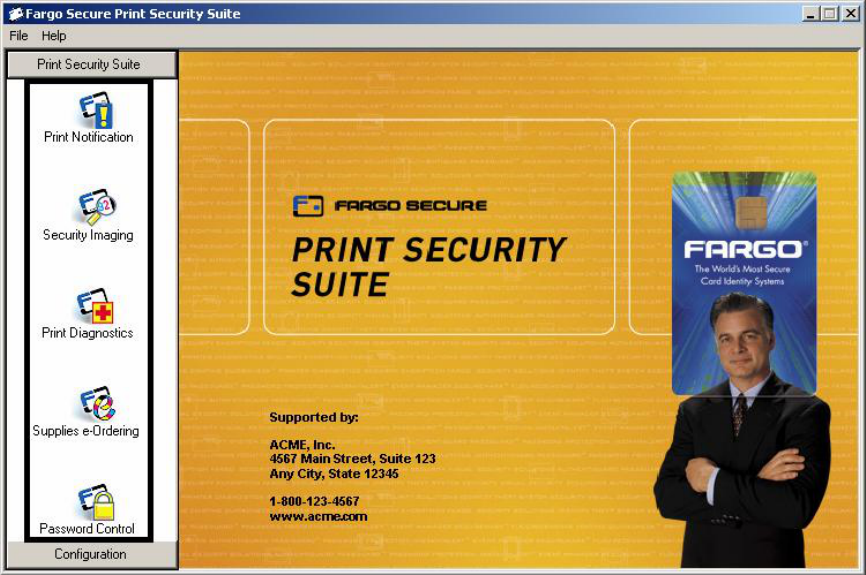
RESTRICTED USE ONLY Fargo Electronics, Inc.
Persona C30 Card Printer User Guide (Rev. .01) 3-3
Print Security Suite – Main Window
Here are the icons for the five (5) applications within the Print Security Suite. See the
Functional Specification section and the Software Instructions section in this same document
for more detailed information on these five (5) applications. Caution: Be sure and save your
work in the Printer Security Suite. By selecting Save All on the File dropdown menu, you can
save your work on all active applications.
SecureMark Media
SecureMark Media is used together with the Print Security Suite to convert a generic Fargo
Printer to a SecureMark Printer. After this conversion, the Printer will only accept Integrator-
specific SecureMark media (Ribbon). The following is the basic process for converting to
SecureMark media.
a. The User installs the Print Security Suite.
b. The CD Installation process prompts the User to launch the Print Security Suite.
c. The Print Security Suite detects the SecureMark Media installed in the Printer and
prompts the User to convert the Printer to be SecureMark enabled.
d. The SecureMark conversion is completed and only Integrator specific SecureMark media
will work in this Printer.