Faurecia Clarion Electronics JE5030 2G/3G Telematics Control Unit User Manual
Clarion Co Ltd 2G/3G Telematics Control Unit
User Manual

Page 1/20
Clarion Confidential
USER MANUAL
TELEMATICS CONTROL UNIT
JE-5030, JE-5031
Confidential and Proprietary Information of
Clarion
Co.,
Ltd
.
(C) 2014 Clarion Co., Ltd. All Rights Reserved.
V
er 1.0
7 Mar 2014
Page 2/20
Clarion Confidential
REVISION HISTORY
Ver. Date Name Status
1.0 7 Mar 2014 M.Kanamori
Initial Release

Page 3/20
Clarion Confidential
−Contents−
1. INTRODUCTION ................................................................................................................................................................................... 4
1.1 Overview ............................................................................................................................................................ 4
1.2 Acronyms ........................................................................................................................................................... 4
2. SYSTEM OVERVIEW ........................................................................................................................................................................... 5
2.1 System Diagram ................................................................................................................................................ 5
2.2 General Description .......................................................................................................................................... 5
2.3 TCU Lineup ........................................................................................................................................................ 5
3. HARDWARE SPECIFICATION .......................................................................................................................................................... 6
3.1 External View and Block Diagram ..................................................................................................................... 6
3.1.1 External Antenna Model (JE-5030) ............................................................................................................ 6
3.1.2 Internal Antenna Model (JE-5031) ............................................................................................................. 7
3.2 Connector........................................................................................................................................................... 8
3.2.1 Main Connector .......................................................................................................................................... 8
3.2.2 Cellular RF Connector (JE-5030) ............................................................................................................... 8
4. OPERATING CONNECTION FOR DEBUG ................................................................................................................................... 9
4.1 Evaluation Environment ........................................................................................................................................... 9
4.2 TCU Control Tool ................................................................................................................................................... 10
5. FCC/IC REGULATORY NOTICES ............................................................................................................................................... 16
APPENDIX A. CONFIGURATION OF CELLULAR TESTER FOR WCDMA SIGNALING CONNECTION ..................... 17
APPENDIX B. INSTALLATION OF THE DRIVER AND THE APPLICATION TO PC FOR DEBUG ............................... 18
APPENDIX C. ACCESSORIES FOR EVALUATION ..................................................................................................................... 19
Page 4/20
Clarion Confidential
1. INTRODUCTION
1.1 Overview
This document shows the user manual of the ‘TCU’.
1.2 Acronyms
Acronym / Definition Description
CL Clarion
TCU Telematics Communication(Control) Unit
CAN Controller Area Network
Page 5/20
Clarion Confidential
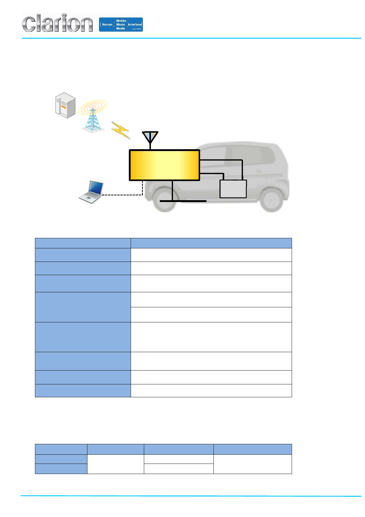
2. SYSTEM OVERVIEW
2.1 System Diagram
2.2 General Description
Item Spec
Power Voltage Typ. 13.5V (9V~16V)
Power Consumption (Max) 1000 mA
Module Information Name: HE920-NA/EU
Manufacturer: Telit Wireless Solutions
Frequency Band
UMTS / HSPA (WCDMA / FDD)
850/1700/1900 MHz(NA),850/900/2100(EU)
GSM / GPRS / EDGE
Quad-band 850/900/1800/1900
Data
HSPA : Down: 14.4Mbps / Up: 5.76Mbps
WCDMA : Down/Up: 384kbps
EDGE : Down/Up: 236.8kbps
GPRS : Down/Up: 85.6kbps
Antenna Gain (Max) External Antenna (JE-5030): 0dBi
Internal Antenna (JE-5031): 0dBi
CAN ISO11898 Compliance / 500kbps
Temperature Range -40°C to +85°C
2.3 TCU Lineup
TCU has two models which are the external antenna model and the internal antenna model. The only different
point is just only the antenna type.
MODEL No. MODEM AntennaType Destination
JE-5030 HE920-NA External Antenna NA
JE-5031 Internal Antenna
CAN
VBAT
TCU GND
BAT
- +
Telematics
Server
UART
Debug PC
Page 6/20
Clarion Confidential
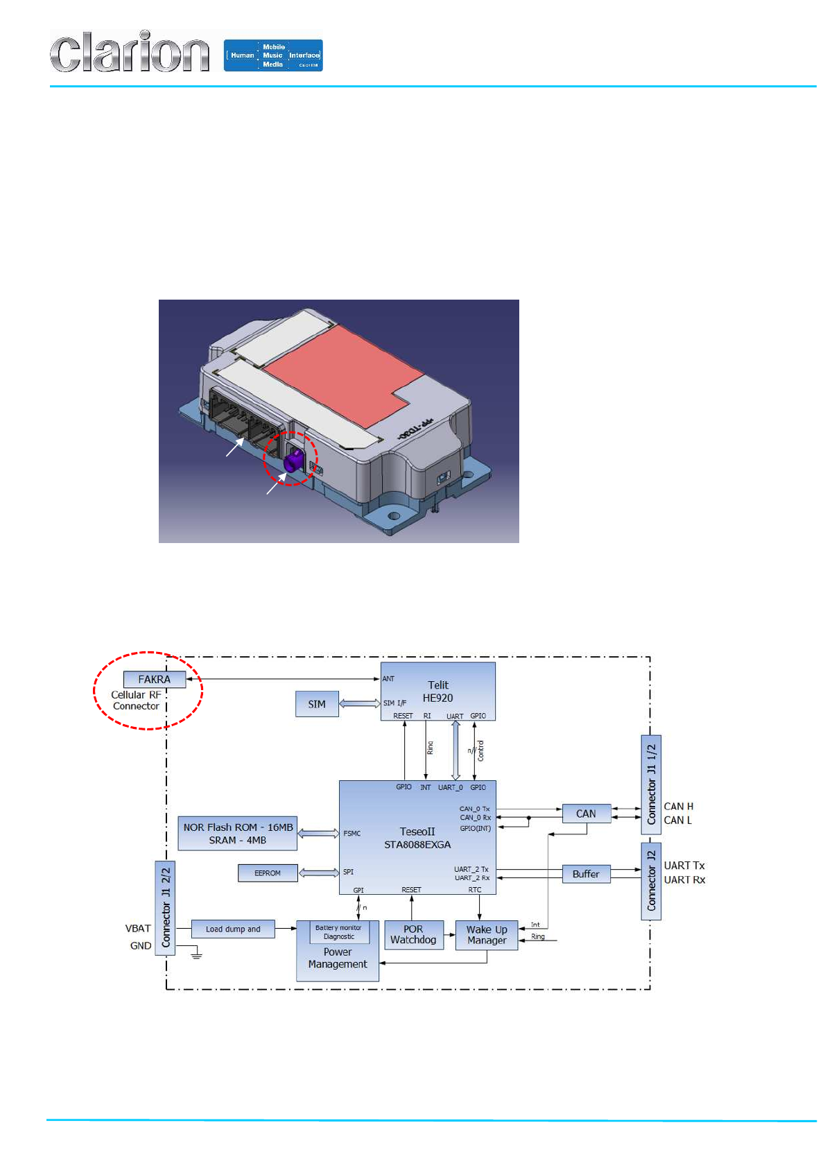
3. HARDWARE SPECIFICATION
3.1 External View and Block Diagram
3.1.1 External Antenna Model (JE-5030)
(1) External View
(2) Block Diagram
Size: 155.0x76.3x38.0 [mm]
Weight: under 200 [g]
Main Connector
Cellular RF Connector
Page 7/20
Clarion Confidential
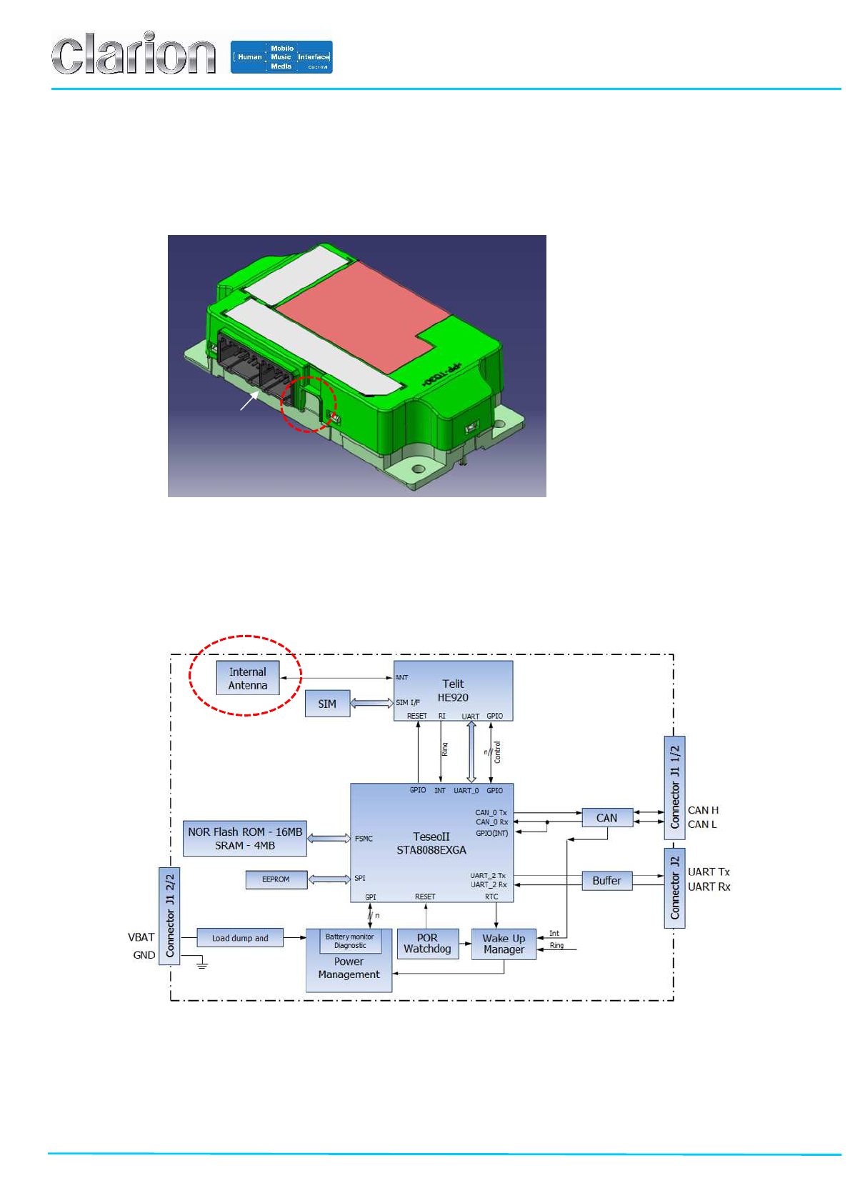
3.1.2 Internal Antenna Model (JE-5031)
(1) External View
(2) Block Diagram
Main Connector
Size: 155.0x76.3x38.0 [mm]
Weight: under 200 [g]
Page 8/20
Clarion Confidential
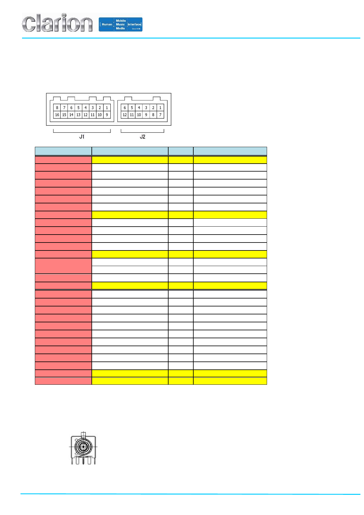
3.2 Connector
3.2.1 Main Connector
The below figure shows the pin-out of main connector of TCU.
Pin Number
Signal Name I/O
Remarks
J1
-
1
VBATT
-
Vehicle Battery (+1
3.5
V)
J1
-
2
Reserved
-
J1-3 Reserved -
J1-4 Reserved -
J1-5 Reserved -
J1-6 Reserved -
J1-7 Reserved -
J1
-
8
CAN (H)
I/O
J1-9 Reserved -
J1-10 Reserved -
J1-11 Reserved -
J1-12 Reserved -
J1
-
13
GND
-
Body Ground
J1-14 Reserved -
Reserved -
J1-15 Reserved -
J1
-
16
CAN (L)
I/O
J2-1 Reserved -
J2-2 Reserved -
J2-3 Reserved -
J2-4 Reserved -
J2-5 Reserved -
J2-6 Reserved -
J2-7 Reserved -
J2-8 Reserved -
J2-9 Reserved -
J2-10 Reserved -
J2
-
11
UART(Tx)
O
for Debug
J2
-
12
UART(Rx)
I
for Debug
3.2.2 Cellular RF Connector (JE-5030)
The following figure shows the cellular RF connector which is based on FAKRA-D. It is used only for the external
antenna model (JE-5030).
Page 9/20
Clarion Confidential
4. OPERATING CONNECTION FOR DEBUG
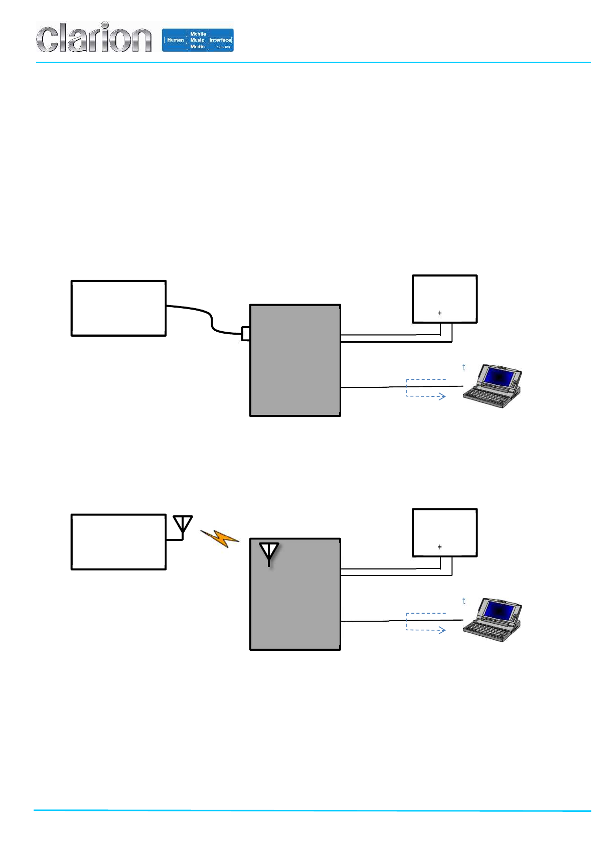
4.1 Evaluation Environment
The following charts show the example of connection diagram for debugging. TCU can be powered up on the
condition as descripted in the chapter 2.2 and debugged over the UART by using the external PC. The only different
point between the external antenna model and the internal antenna model is the way to establish the RF connection.
(1) External Antenna Model (JE-5030)
(2) Internal Antenna Model (JE-5031)
Test Request
Response
TCU
DC
Power
13.5V (9V~16V)
+
-
Cellular
Communication
Tester
Debug-PC
Power source
Debug
(UART)
Test Request
Response
DC
Power
13.5V (9V~16V)
+
-
Cellular
Communication
Tester
Debug-PC
Power source
Debug
(UART)
TCU
Cellular
RF Connector
Page 10/20
Clarion Confidential
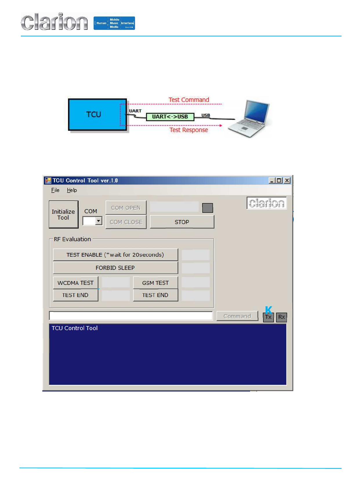
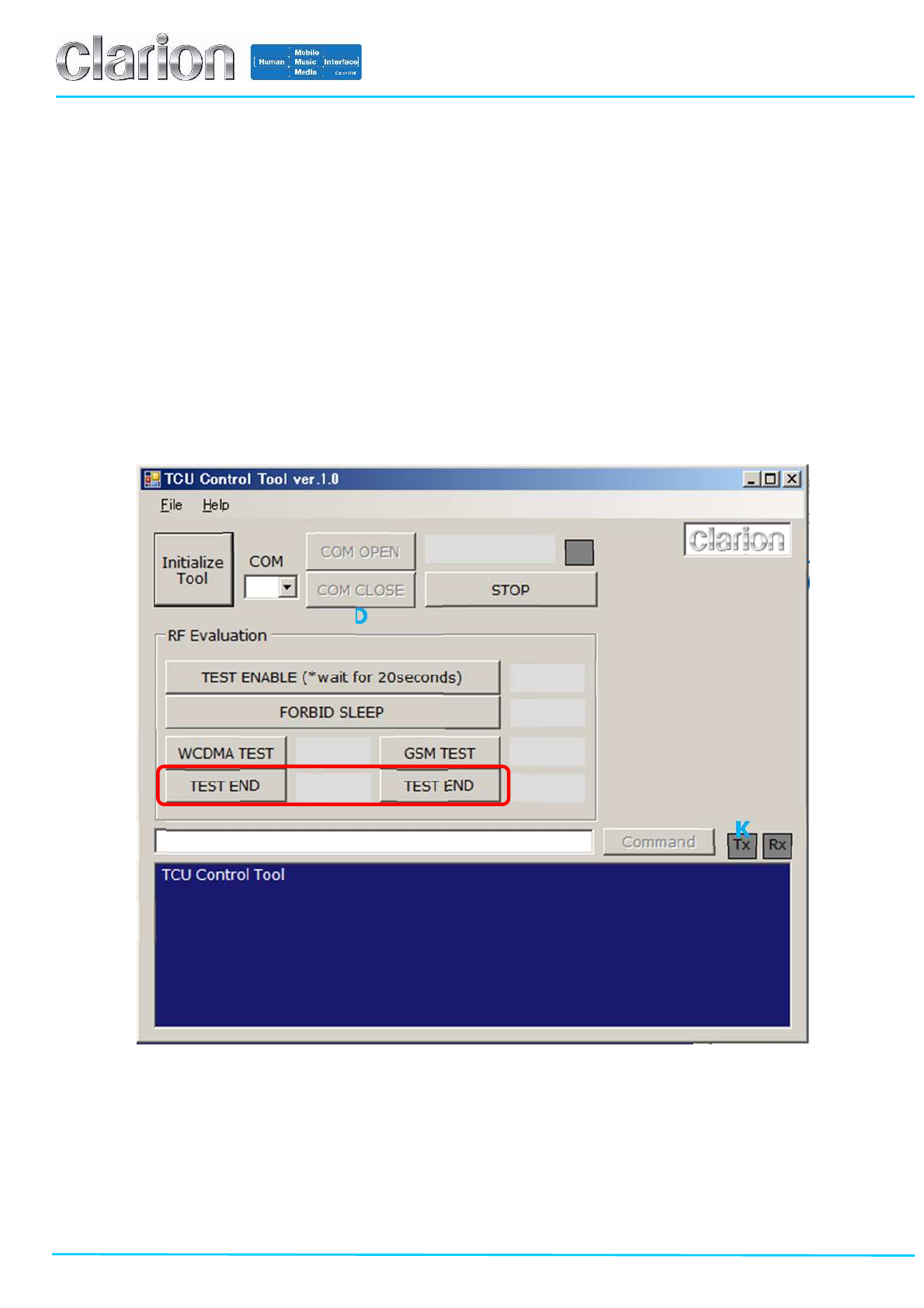
4.2 TCU Control Tool
TCU can be controlled by the dedicated application “TCU Control Tool”, which is the Windows application delivered
by Clarion.
4.2.1 Operation Manual
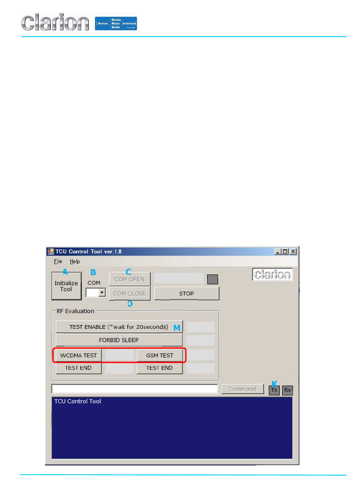
Here is the view of the TCU Control Tool as below.
A B C
D
E F
G
H
I
N
P
Q R S T
U V W Y J K L
M
O
Page 11/20
Clarion Confidential
Description of the button and the enterable white box in the TCU Control Tool:
# Name and View
Type Description
A Initialize Tool Button The ‘Initialize Tool’ is the button to initialize the TCU Control Tool.
B COM Enterable
box The ‘COM’ is the enterable white box to select the serial port number.
It is able to be selected from the drop-down list or be keyed by a keyboard.
C COM OPEN Button The ‘COM OPEN’ is the button to open the COM port number selected on the ‘COM’
D COM CLOSE Button The ‘COM CLOSE’ is the button to close the COM port number selected on the ‘COM’
E Tool Status Message Display The ‘Tool Status Message’ is the display to show the status of TCU Control Tool.
A message is visible when the TCU Control Tool is running.
F Tool Running Indicator
Display The ‘Tool Running Indicator’ is the display to show the running condition of the TCU Control Tool.
When TCU Control Tool is running, the Tool Running Indicator is blinking on and off.
This is just only for reference.
G STOP TOOL Button The ‘STOP TOOL’ is the button to stop the TCU Control Tool.
H Command Display Display The ‘Command Display’ is the display to show the dialogue between TCU and the TCU Control Tool.
I Command Box Enterable
box The ‘Command Box’ is the enterable box to enter the command you want to send to TCU.
J Send Command Button The ‘Send Command’ is the button to send the text of Command Box to TCU.
K TX STATE Display The ‘TX STATE’ is the display to show the condition of sending a command from the TCU Control
Tool to the TCU.
While the TCU Control Tool is sending a command the TX STATE is colored green.
L RX STATE Display The ‘RX STATE’ is the display to show the condition of receiving a command from the TCU to the
TCU Control Tool.
While the TCU Control Tool is receiving a command the RX STATE is colored orange.
M TEST ENABLE Button
The ‘TEST ENABLE’ is the button to enter the TCU in TEST ENABLE MODE.
The TCU is able to accept sending/receiving of the other commands during the TEST ENABLE
MODE.
The TEST ENABLE MODE is reset after TCU restarted.
N RES TEST ENABLE Display The ‘RES TEST ENABLE’ is the display to show the result message of the TEST ENABLE.
If the TEST ENABLE is passed, the word ‘OK’ is displayed in the RES TEST ENABLE.
It takes 20senconds to get the result after powered +13.5V.
O FORBID SLEEP Button The ‘FORBID SLEEP’ is the button to enter the TCU in FORBID SLEEP MODE.
The TCU is able to be working during FORBID SLEEP MODE.
The FORBID SLEEP MODE is reset after TCU restarted.
P RES FORBID SLEEP Display The ‘RES FORBID SLEEP’ is the display to show the result message of the FORBID SLEEP.
If the FORBID SLEEP is passed, the word ’OK’ is displayed in the RES FORBID SLEEP.
Q WCDMA TEST Button
The ‘WCDMA TEST’ is the button to enter the TCU in WCDMA TEST MODE.
The TCU is able to communicate with WCDMA signaling tester during WCDMA TEST MODE.
The WCDMA TEST MODE is kept after TCU restarted. The WCDMA TEST MODE is stored in the non-
volatile memory.
R RES WCDMA TEST Display The ‘RES WCDMA TEST’ is the display to show the result message of the WCDMA TEST.
If the WCDMA TEST is passed, the word ’OK’ is displayed in the RES WCDMA TEST.
S WCDMA TEST END Button The ‘WCDMA TEST END’ is the button to return the TCU in NORMAL MODE.
The TCU should be entered in NORMAL MODE when the test of connection with tester is ended.
T RES WCDMA TEST
END Display The ‘RES WCDMA TEST END’ is the display to show the result of the RES WCDMA TEST END.
If the WCDMA TEST END is passed, the word ‘OK’ is displayed in the RES WCDMA TEST END.
U GSM TEST Button
The ‘GSM TEST’ is the button to enter the TCU in GSM TEST MODE.
The TCU is able to communicate with GSM signaling tester during GSM TEST MODE.
The GSM TEST MODE is kept after TCU restarted. The GSM TEST MODE is stored in the non-volatile
memory.
V RES GSM TST Display The ‘RES GSM TEST’ is the display to show the result message of the GSM TEST.
If the GSM TEST is passed, the word ’OK’ is displayed in the RES GSM TEST.
W GSM TEST END Button The ‘GSM TEST END’ is the button to return the TCU in NORMAL MODE.
The TCU should be entered in NORMAL MODE when the test of connection with tester is ended.
Y RES GSM TEST END Display The ‘RES GSM TEST END’ is the display to show the result of the RES GSM TEST END.
If the GSM TEST END is passed, the word ‘OK’ is displayed in the RES GSM TEST END.
Page 12/20
Clarion Confidential
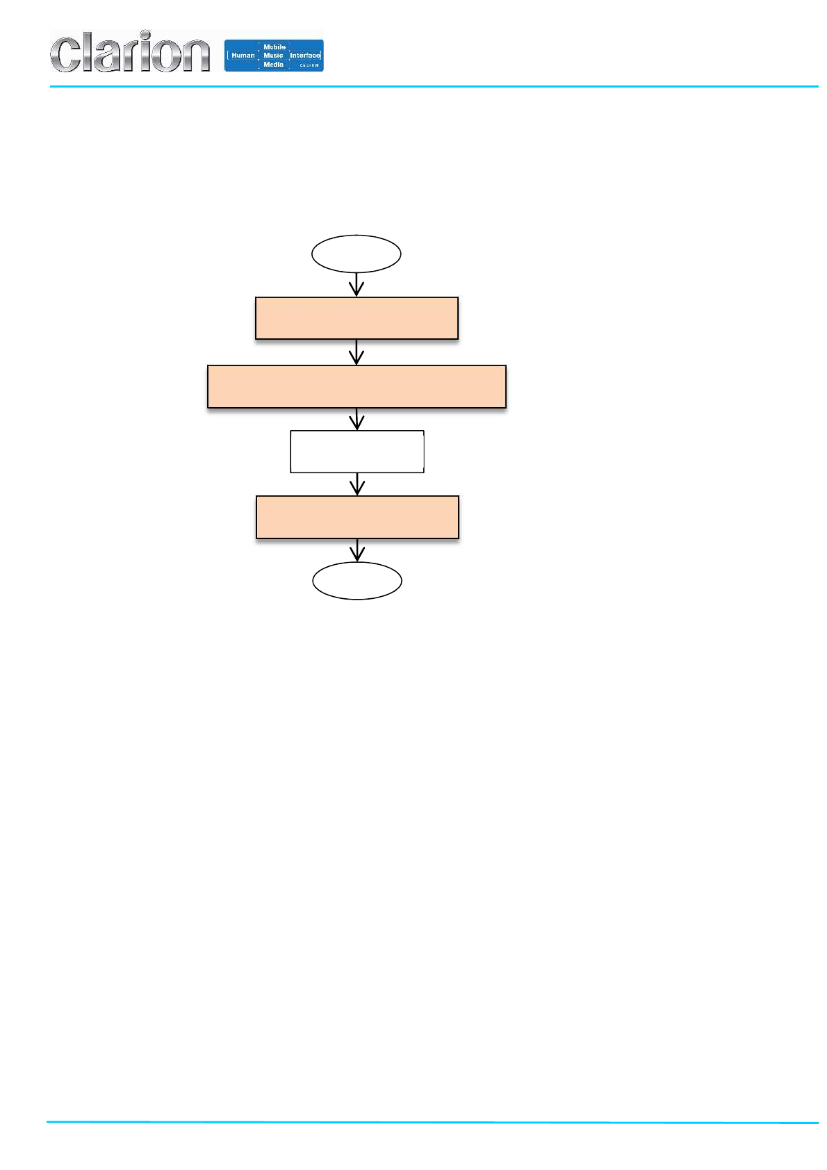
4.2.2 Procedure
TCU can be controlled according to the below procedure by using “TCU Control Tool”.
Test the TCU according to the flow chart as below.
START
END
Configure the TCU
Communicate with the Cellular Tester
End the Test
TESTING…
Procedure of the RF TEST
Page 13/20
Clarion Confidential
(1) Configure the TCU
The below is the procedure to configure the TCU to establish the RF communication with the cellular tester.
1. Setup the evaluation environment according to chapter 4.1 and Appendix C.
2. Start the program ‘TCU Control Tool’.
3. Click the button A.
4. Select the COM port number in the B. COM port name is ‘USB Serial Port’. It can be found in the device manager on
windows PC.
5. Click the button C. And wait until ‘ACTIVE’ is displayed on E.
6. Supply DC Power 13.5V(9V~16V) to the TCU.
7. Click the button M. And wait to until ‘ACTIVE’ is displayed on N.
Note: It can take about 20seconds to show the result OK.
8. Click the button O. And wait until ‘OK’ is displayed on P.
9. (i) In the case of communication with WCDMA signaling;
Click the button Q. And wait until ‘OK’ is displayed on R.
(ii) In the case of communication with GSM signaling;
Click the button S. And wait until ‘OK’ is displayed on T.
10. Click the button D.
11. Power off the TCU.
12. Configuration of TCU is completed.
A B C
D
E F
G
H
I
N
P
Q R S T
U V W Y J K L
3 4 5
O
M
7
9
10
8
Page 14/20
Clarion Confidential
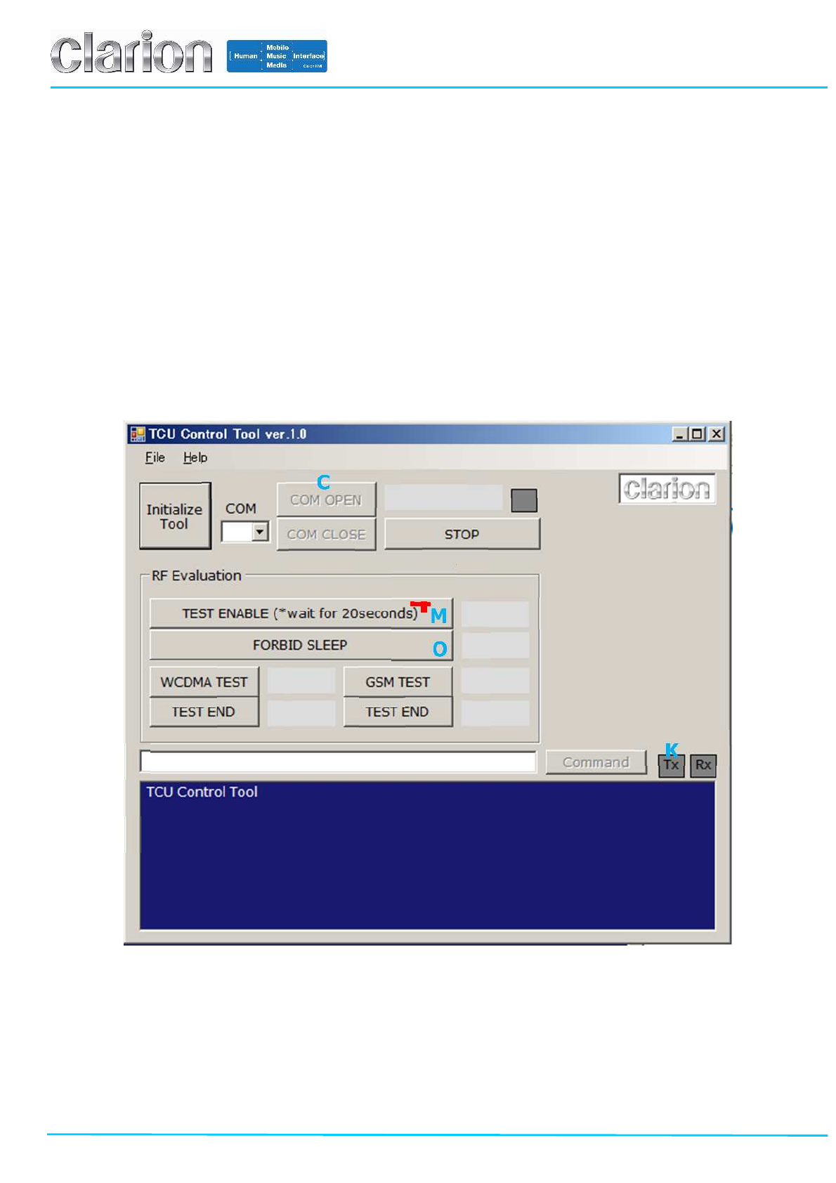
(2) Procedure to Communicate with the Cellular Tester
In order to establish the RF signaling connection with the cellular tester, the dedicated configuration should be
needed, because TCU implements the embedded SIM chip for the real commercial network. The below is the
procedure to establish the RF signaling connection with the cellular tester. Besides, the detail information of the
configuration of the cellular tester is shown in Appendix A.
1. Configure the setting of the cellular tester referring to the Appendix A.
2. Click the button C. And wait until ‘ACTIVE’ is displayed on E.
3. Supply DC Power 13.5V(9V~16V) to the TCU.
4. Click the button M. And wait until ‘OK’ is displayed on N.
Note: It can take about 20seconds to see the result OK.
5. Click the button O. And wait until ‘OK’ is displayed on P.
6. Execute the RF test.
A B C
D
E F
G
H
I
N
P
Q R S T
U V W Y J K L
2
O
M
4
5
Page 15/20
Clarion Confidential
(3) Procedure to End the Test
The below is the procedure to end the test after the testing is done.
1. (i) In the case of communication with WCDMA signaling;
Click the button U. And wait until ‘OK’ is displayed on V.
(ii) In the case of communication with GSM signaling;
Click the button W. And wait until ‘OK’ is displayed on Y.
2. Click the button D.
3. Power off the TCU.
A B C
D
E F
G
H
I
N
P
Q R S T
U V W Y J K L
O
M
1
2

Page 16/20
Clarion Confidential
5. FCC/IC Regulatory notices
Compliance Statements:
This device complies with Part 15 of the FCC. Operation is subject to the following two conditions:
(1) this device may not cause harmful interference, and
(2) this device must accept any interference received, including interference that may cause undesired operation.
Modifications not expressly approved by Clarion Co., Ltd. could void the user’s authority to operate the equipment.
This equipment has been tested and found to comply with the limits for a Class B digital device, pursuant to Part 15
of the FCC Rules. These limits are designed to provide reasonable protection against harmful interference in a
residential installation. This equipment generates, users and can radiate radio frequency energy and, if not installed
and used in accordance with the instructions, may cause harmful interference to radio communications. However,
there is no guarantee that interference will not occur in a particular installation. If this equipment does cause harmful
interference to radio or television reception, which can be determined by turning the equipment off and on, the user is
encouraged to try to correct the interference by one or more of the following measures:
- Reorient or relocate the receiving antenna.
- Increase the separation between the equipment and receiver.
- Connect the equipment into an outlet on a circuit different from that to which the receiver is connected.
- Consult the dealer or an experienced radio/TV technician for help.
Radiofrequency radiation exposure Information:
This equipment complies with FCC radiation exposure limits set forth for an uncontrolled environment.
This equipment should be installed and operated with minimum distance of 20 cm between the radiator and your
body.
This transmitter must not be co-located or operating in conjunction with any other antenna or transmitter.
Information sur l’exposition au rayonnement electromagnetique :
Cet equipement est conforme aux limites d’Insdustrie Canada concernant l’exposition aux
rayonnements electromagnetiques dans un environnement non controle.
L’equipement doit etre installe et utilise a une distance minimum de 20 cm entre le transmetteur et votre corps.
Ce transmetteur ne doit pas etre place au meme endroit ou utilise simultanement avec un autre
transmetteur ou antenne.
CAN ICES-3 (B)/NMB-3(B)

Page 17/20
Clarion Confidential
Appendix A. Configuration of Cellular Tester for WCDMA Signaling Connection
As described above, TCU implements the embedded SIM (eSIM) chip for the real commercial carrier, so the
dedicated configuration of the cellular tester (pseudo base station) should be needed in order to establish the RF
connection with it.
Specifically, the process of authentication and security has to be skipped according to the below configuration of the
cellular tester.
1. CMW500 (ROHDE&SCHWARTZ)
[Network]
[Security Settings]
- Authentication: OFF
- Security: OFF
2. MT8820/MT8815(ANRITSU)
[Call Processing Parameter]
- Integrity Protection: OFF
- Ciphering: OFF

Page 18/20
Clarion Confidential
Appendix B. Installation of the driver and the application to PC for debug
As described above, TCU should be controlled by an external PC for debug when RF testing.
Before the test, execute the setup of the PC according to the below.
Please note that an external PC for debug should be Windows PC.
1. DRIVER
Double-click the file ‘CDM v2.08.30 WHQL Certified.exe’, which is the driver installer for the serial cable CL
delivered by CL.
Install the driver according to instructions on screen.
2. Application
Double-click the file ‘setup.exe’ in the folder ’TCU Control Tool Ver.**’, which is the installer of the TCU Control
Tool.
Install the driver according to instructions on screen.

Page 19/20
Clarion Confidential
Appendix C. Accessories for Evaluation
As described above, the following accessories are used for evaluation.
Please connect according to the below when you test the TCU.
1. Power Cable
A colored YELLOW wire with banana plug should be connected to DC Power 13.5V (9~16V).
A colored BLACK wire with banana plug should be connected to the GND.
The other wires except them are not used and should be opened.
Refer to chapter 3.2 about the connector pin-out of TCUs
2. Serial Cable
The only three wires are used for serial communication.
The other wires except them are not used and should be opened.
Refer to chapter 3.2 about the connector pin-out of TCU.
To the TCU To the GND
To the DC Power 13.5V
OPEN
Don’t Use
OPEN
Don’t Use DC
Power
+
-
TCU
To the TCU To the PC for Debug
OPEN
Don’t Use
TCU
Page 20/20
Clarion Confidential
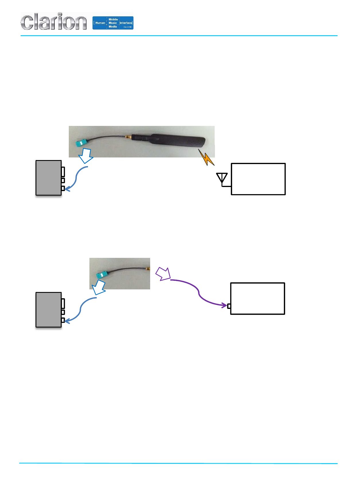
3. Antenna
This is for the external antenna model (JE-5030).
In the case of ‘wireless’ communication with the cellular tester;
The antenna is connected to the TCU via the SMA gender changer female/female adapter and FAKRA-SMA
conversion cable.
In the case of ‘wired’ communication with the cellular tester;
The TCU is connected to the cellular tester via the FAKRA-SMA conversion cable.
TCU
To the TCU
Cellular
Communication
Tester
TCU
To the TCU
Cellular
Communication
Tester
To the Cellular Tester