Feig Electronic ANT1300680 Security Gate User Manual M71104 1e ID B
Feig Electronic GmbH Security Gate M71104 1e ID B
UserManual.wiki
>
Feig Electronic
>
ANT1300680 User Manual
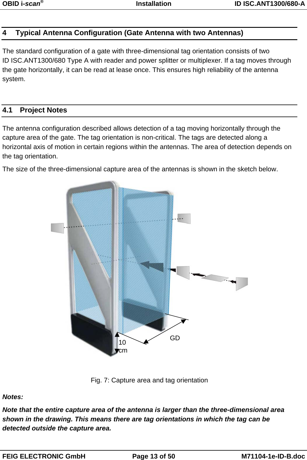
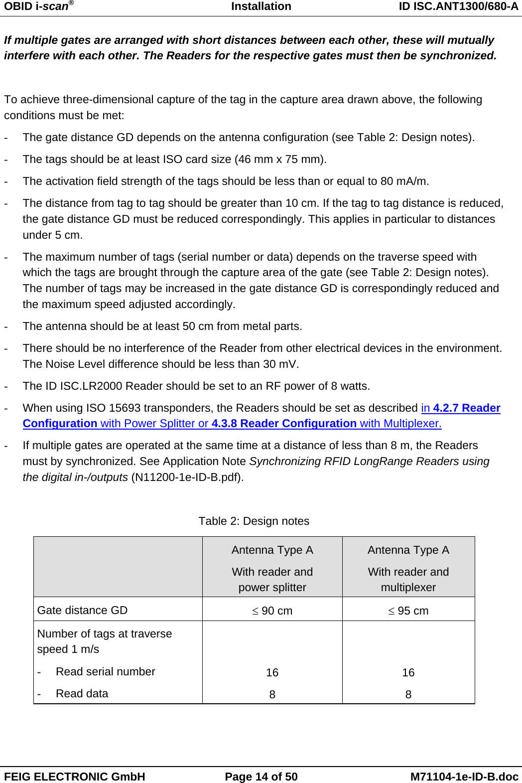
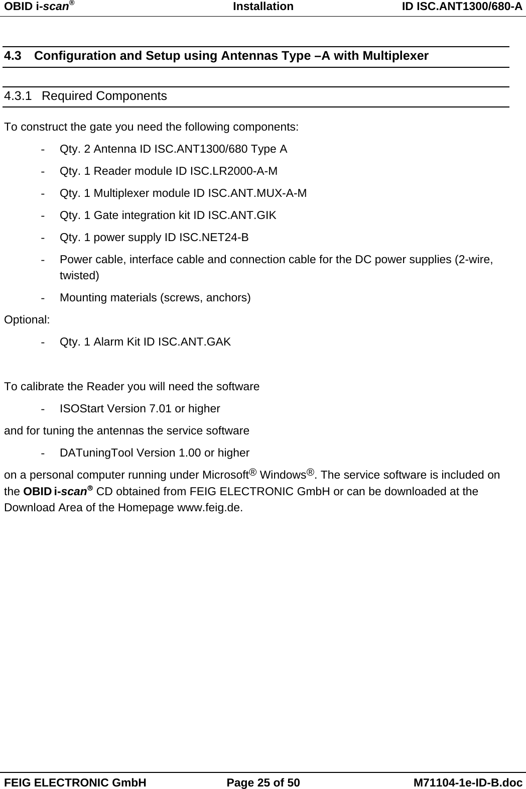
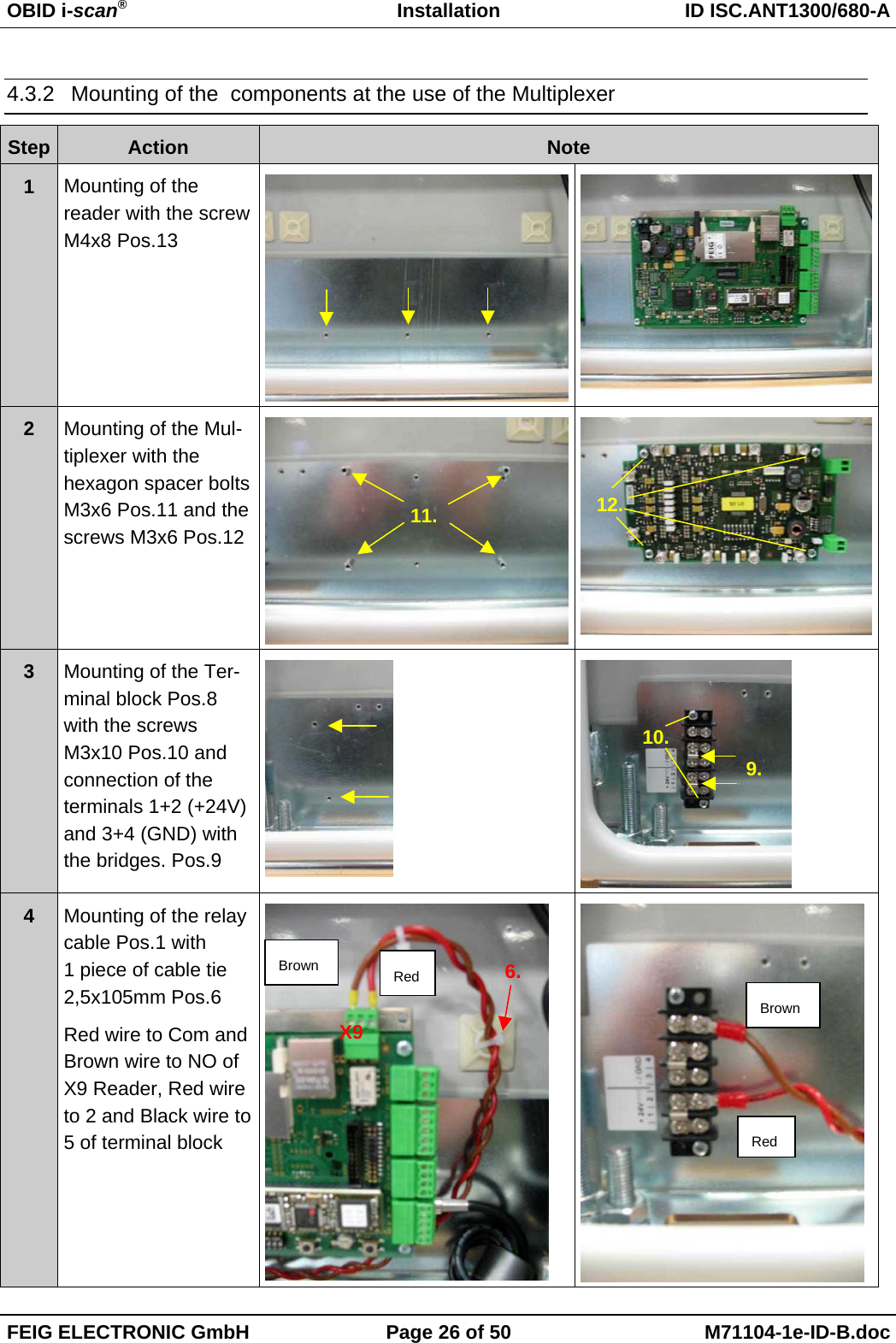
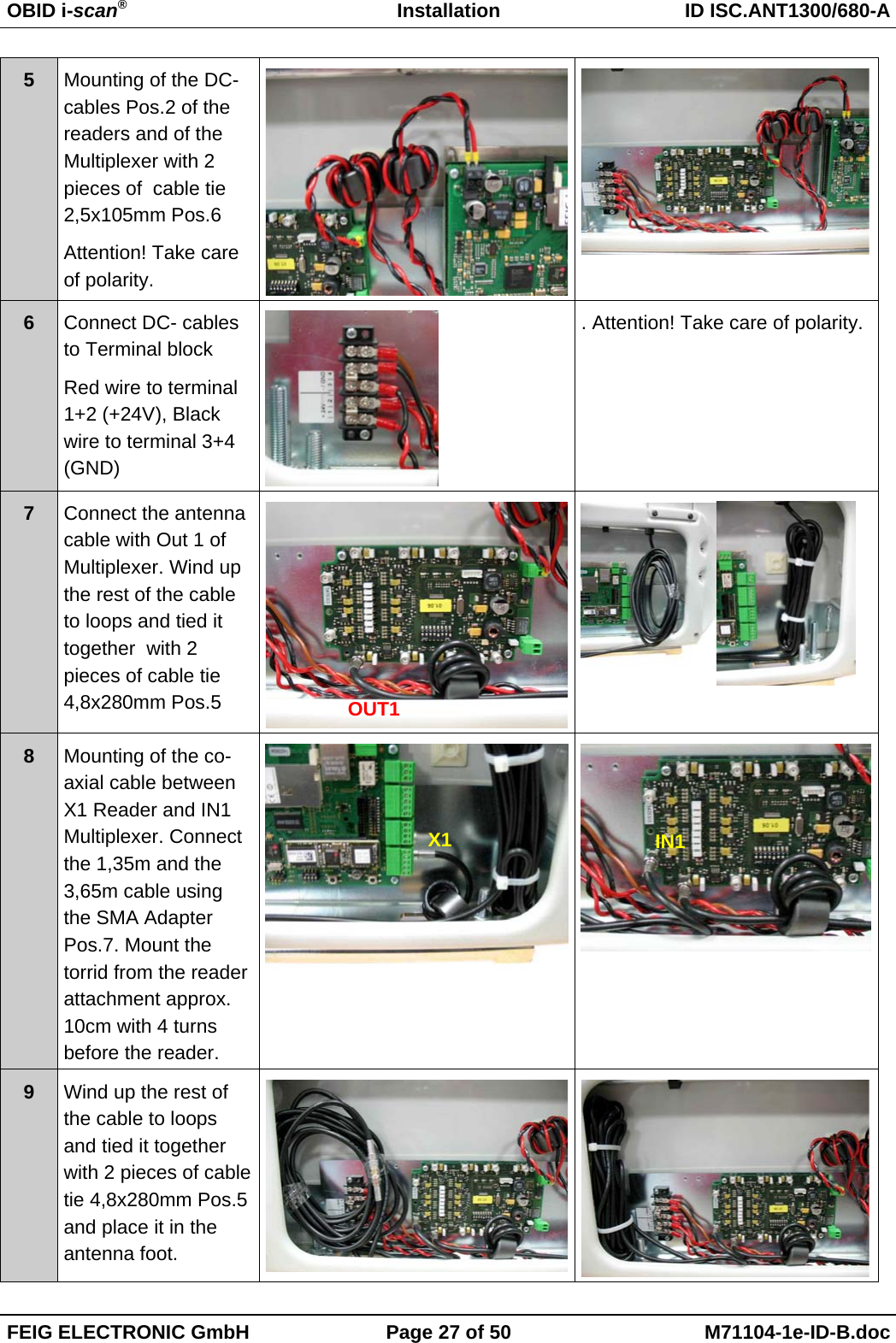
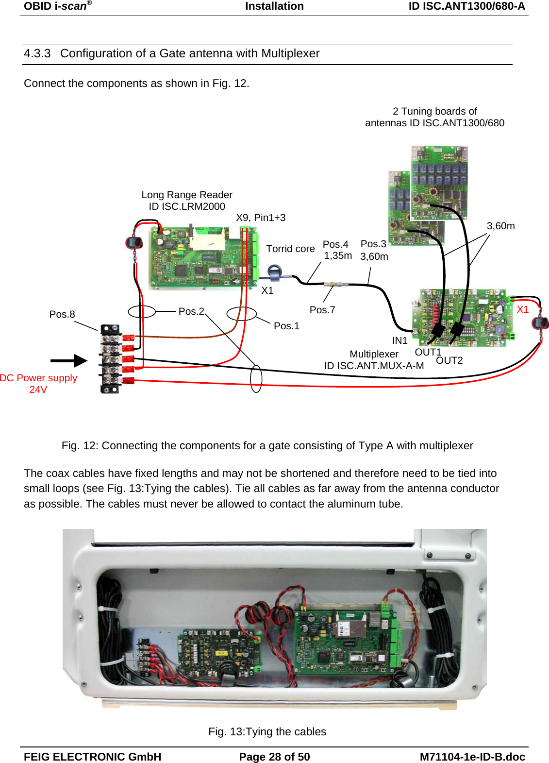
Installation Manual
Navigation menu
Upload a User Manual
Namespaces
Wiki Guide
HTML
PDF
Info
Views
User Manual
Discussion / Help
Navigation
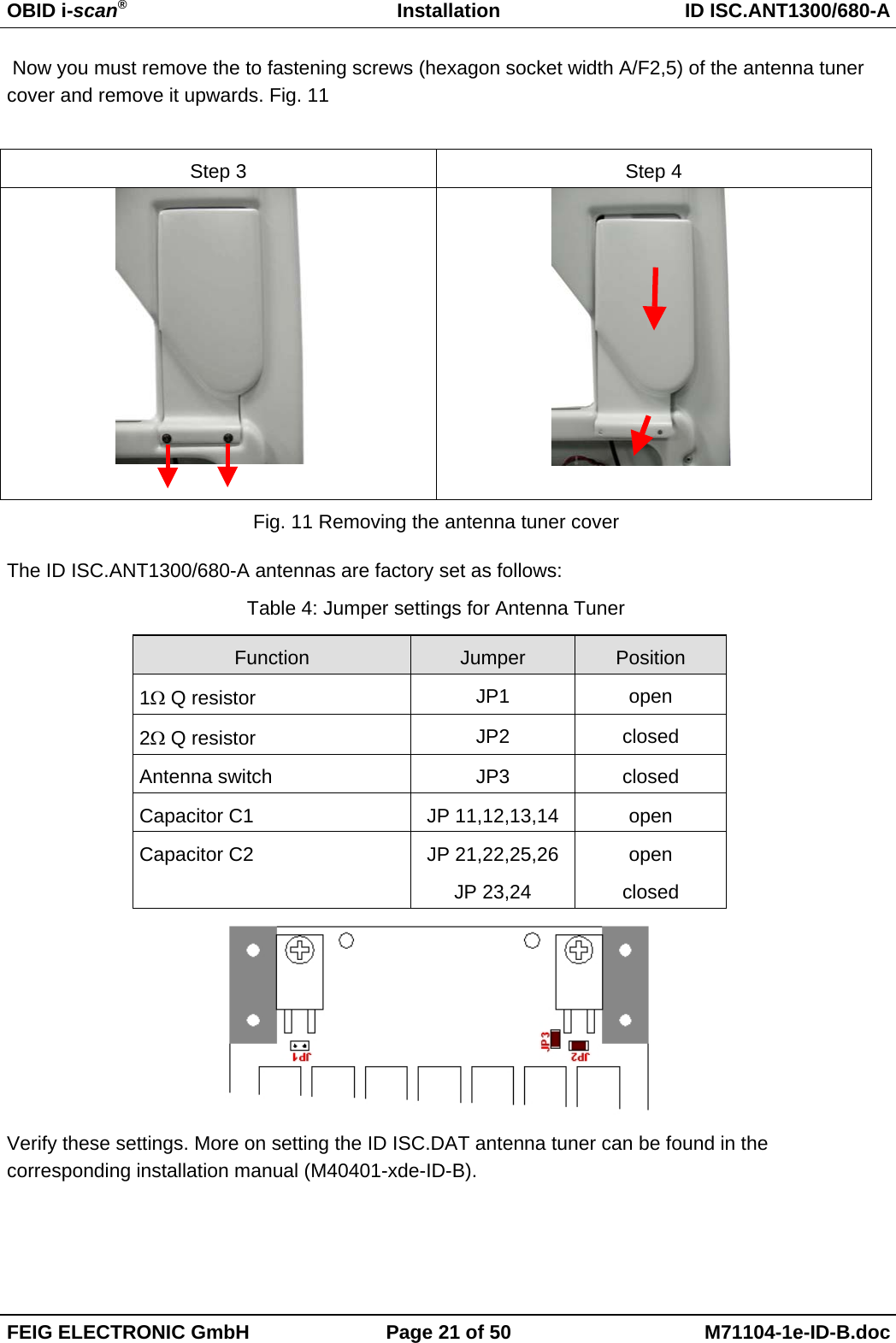
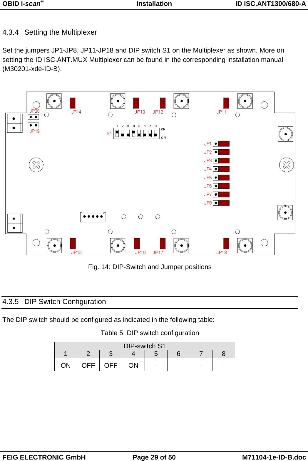
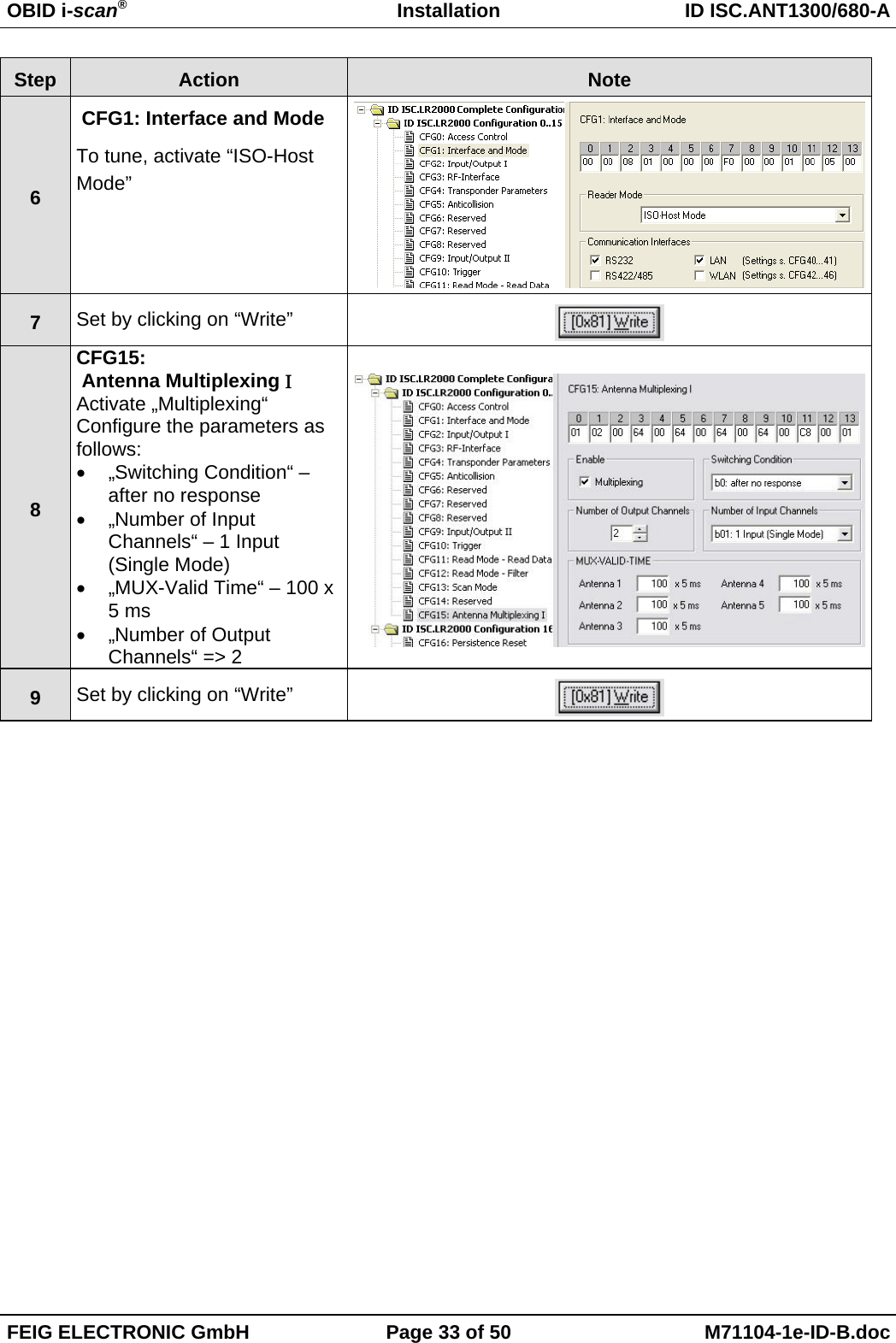
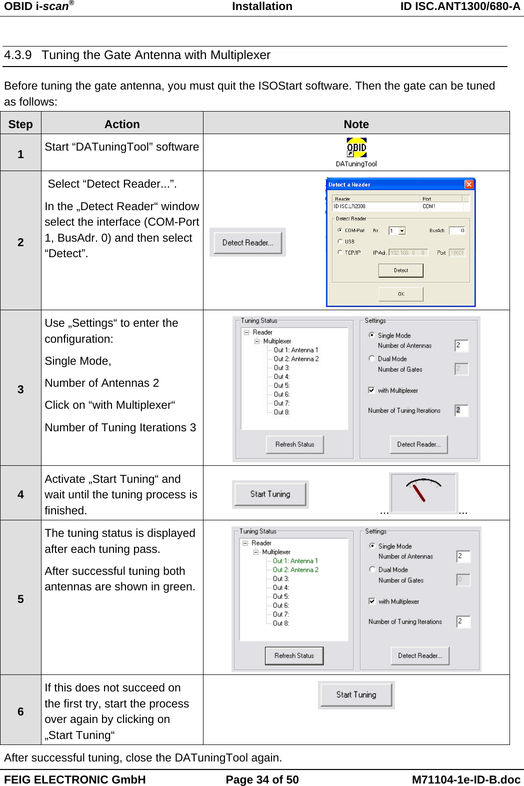
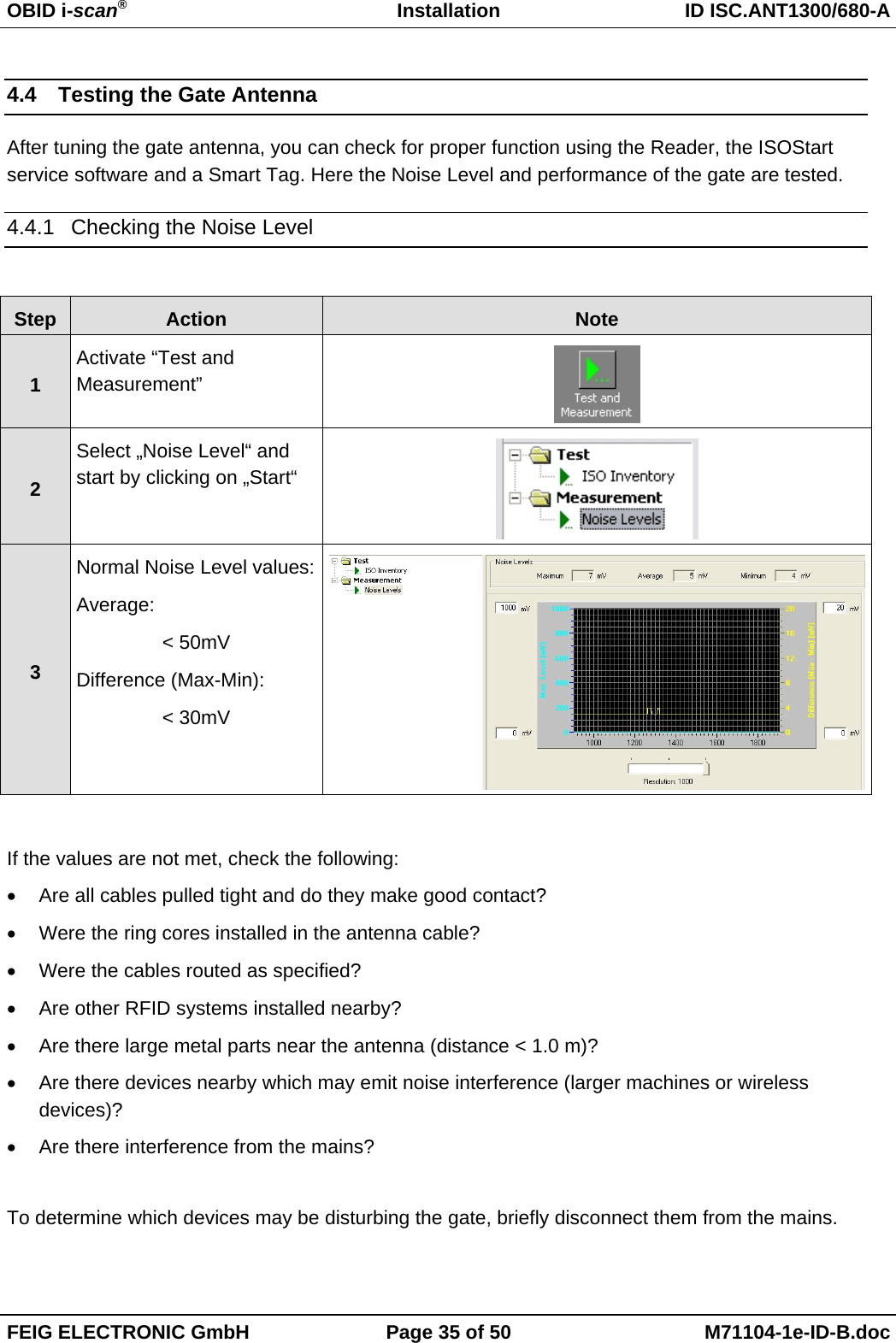
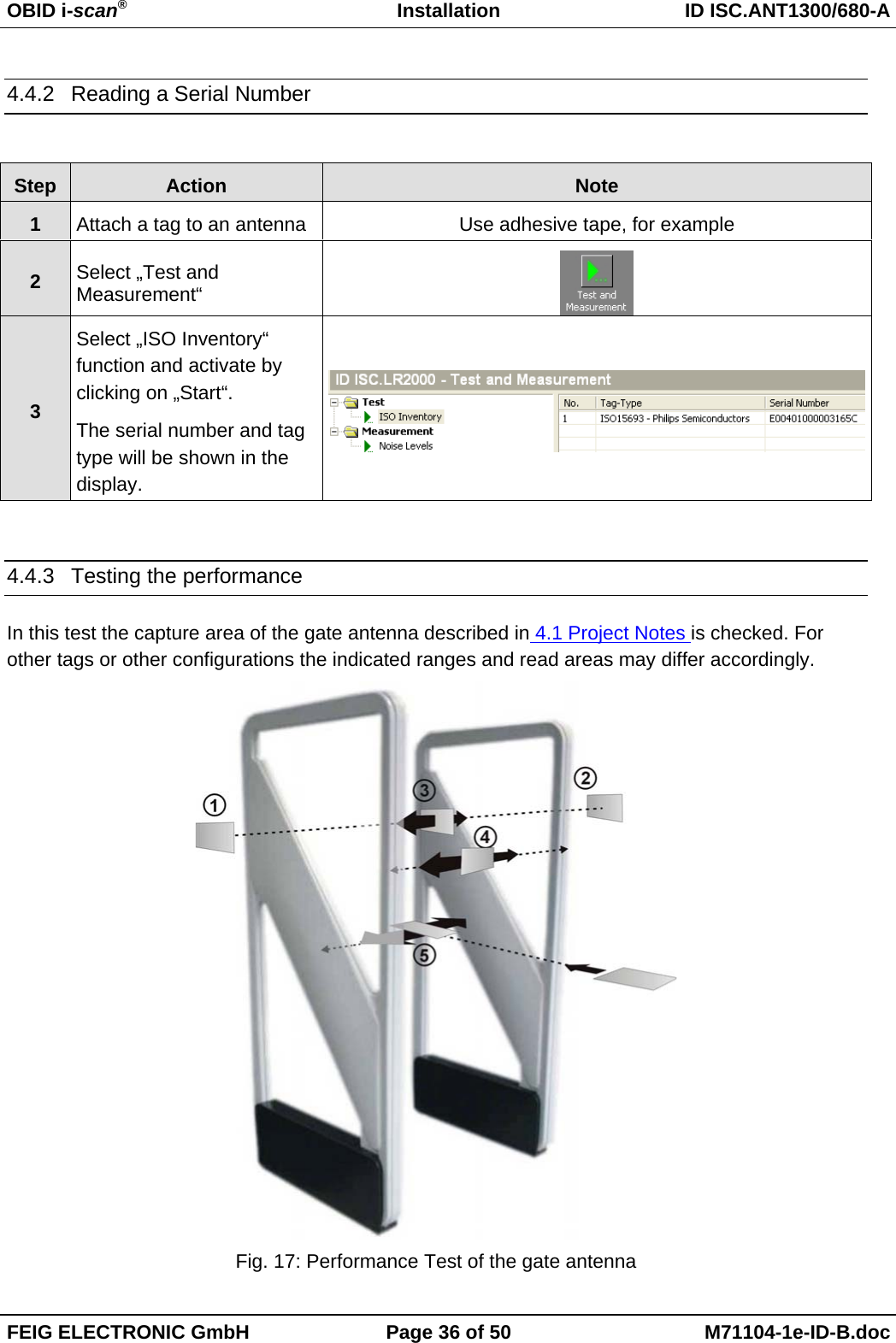
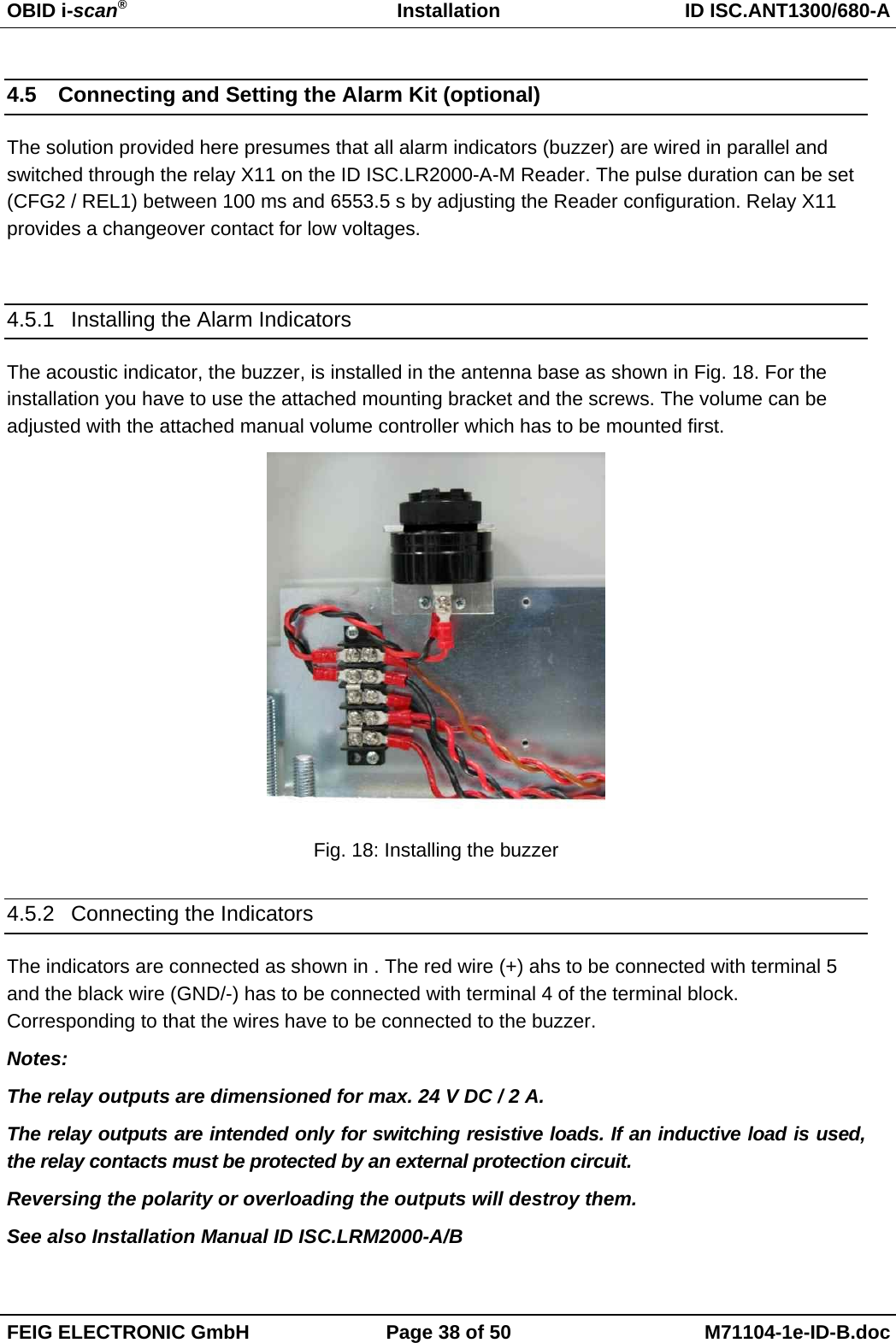
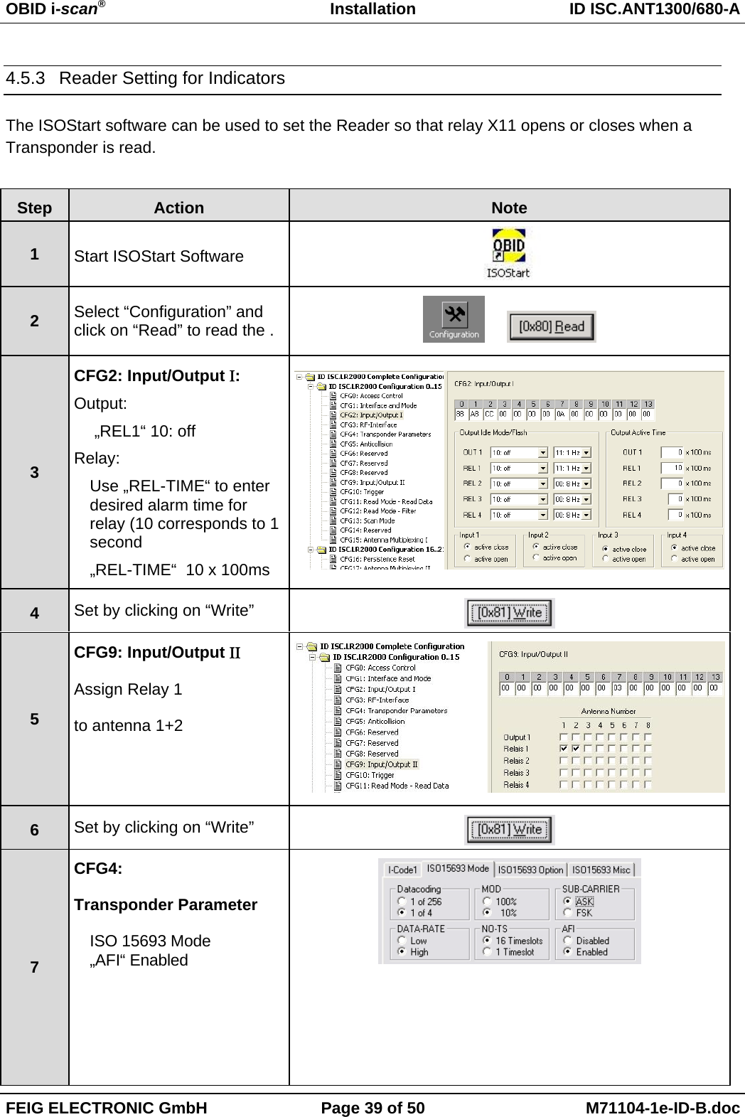
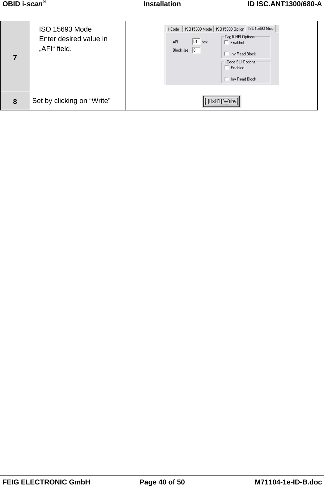
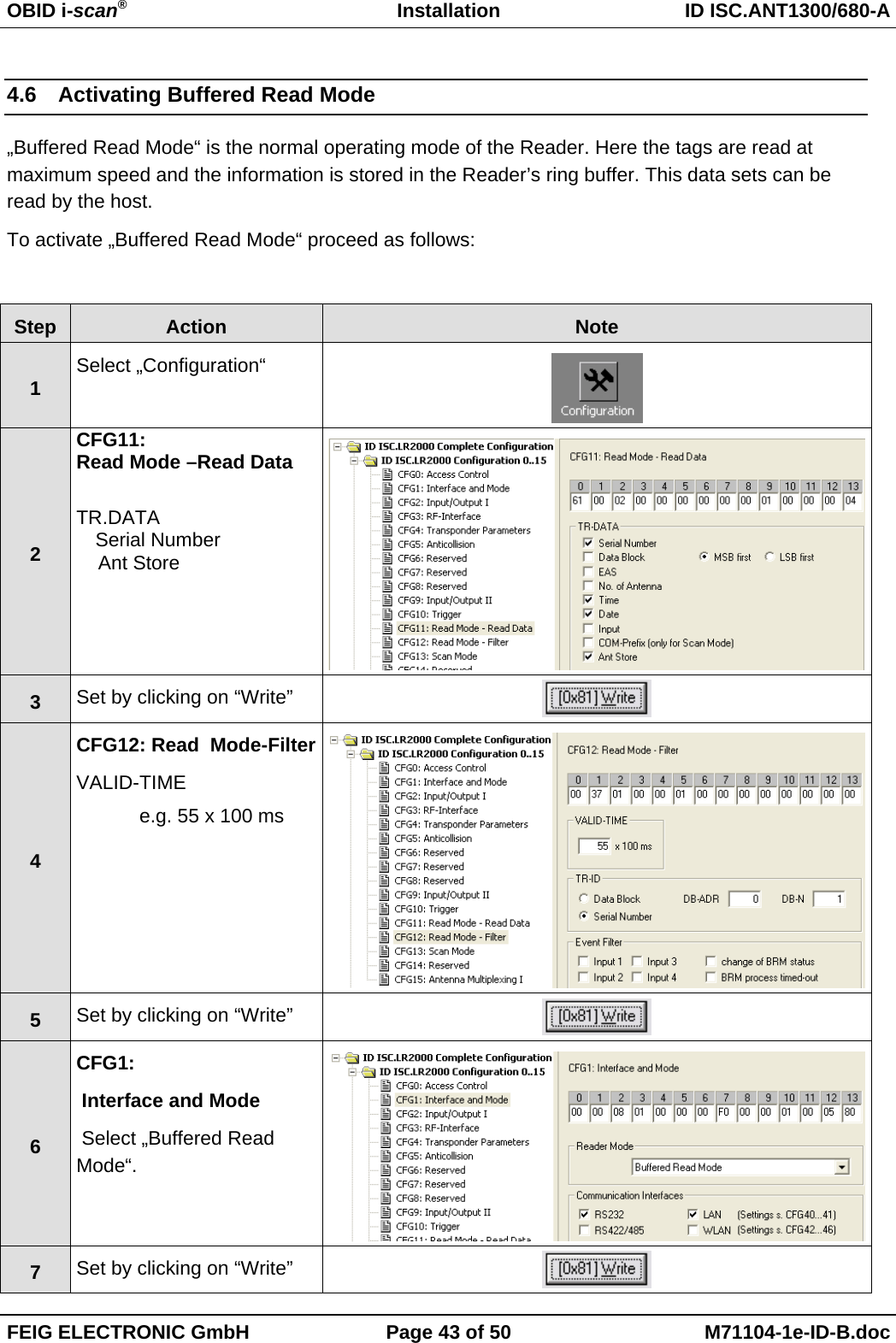
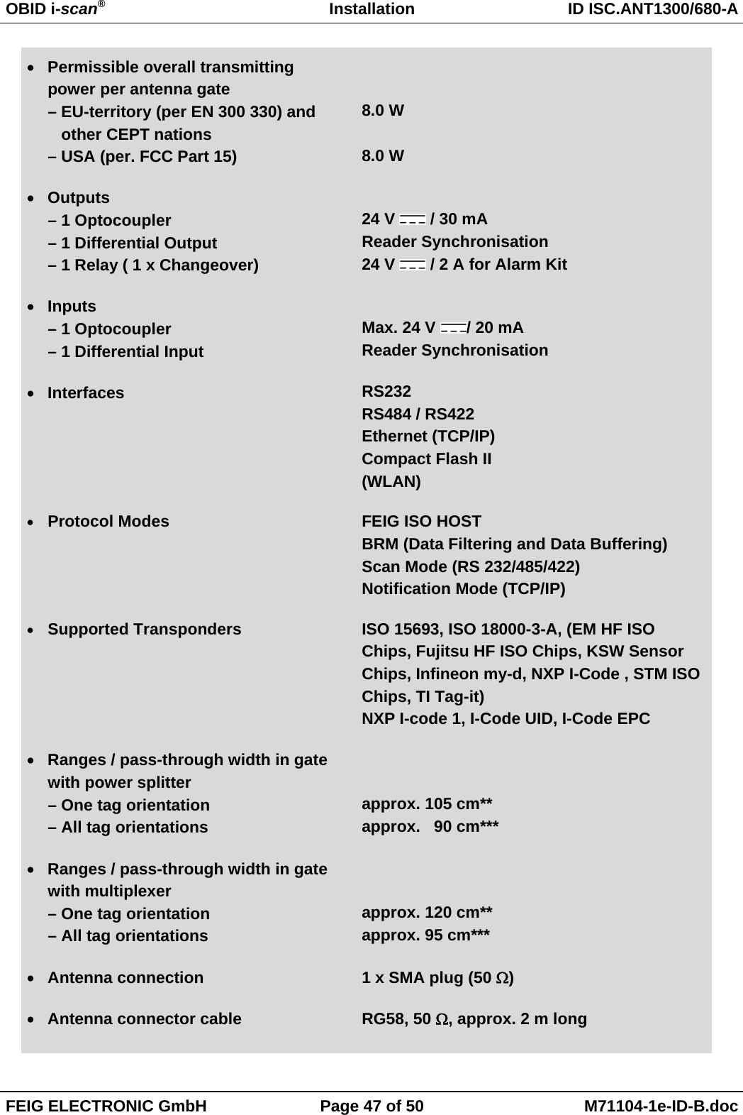
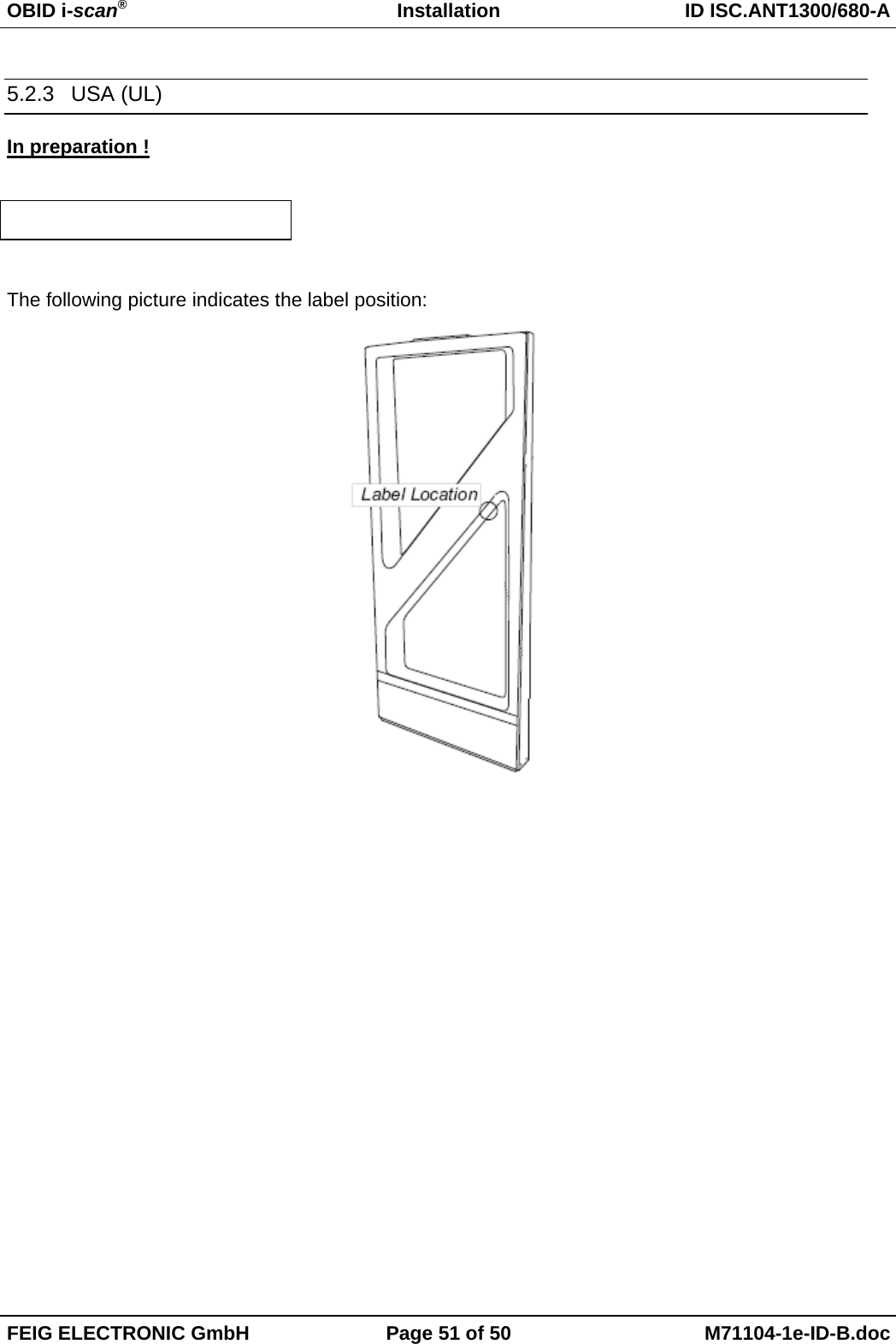
![OBID i-scan®Installation ID ISC.ANT1300/680-AFEIG ELECTRONIC GmbH Page 41 of 50 M71104-1e-ID-B.doc4.5.4 Programming a Transponder with the AFI ByteIf the transponders will remain on the object when leaving the storage location, they must first becancelled. This is generally done by writing to a particular area of the transponder.The AFI byte (Application Family Identifier) is useful for this purpose, since it is contained in nearlyall transponder models in the 13.56 MHz family. To cancel, simply write a different code to thetransponder than for valid transponders which trigger an alarm.Step Action: Note:1Select „Commands“2Place the Transponder in theantenna field (Antenna 1)Select [0x01] InventorySelect New InventoryRequested3Read UID by clicking on„Send“4The serial number, DSFIDand Transponder type aredisplayed in a window.Write down the serial numberof the Transponder5Select „[0x27] Write AFI“ADR:1: addressedSerial Number:Select TransponderAFI:Desired AFI Number (notequal to 00)6Read UID by clicking on„Send“](https://usermanual.wiki/Feig-Electronic/ANT1300680/User-Guide-900174-Page-40.png)
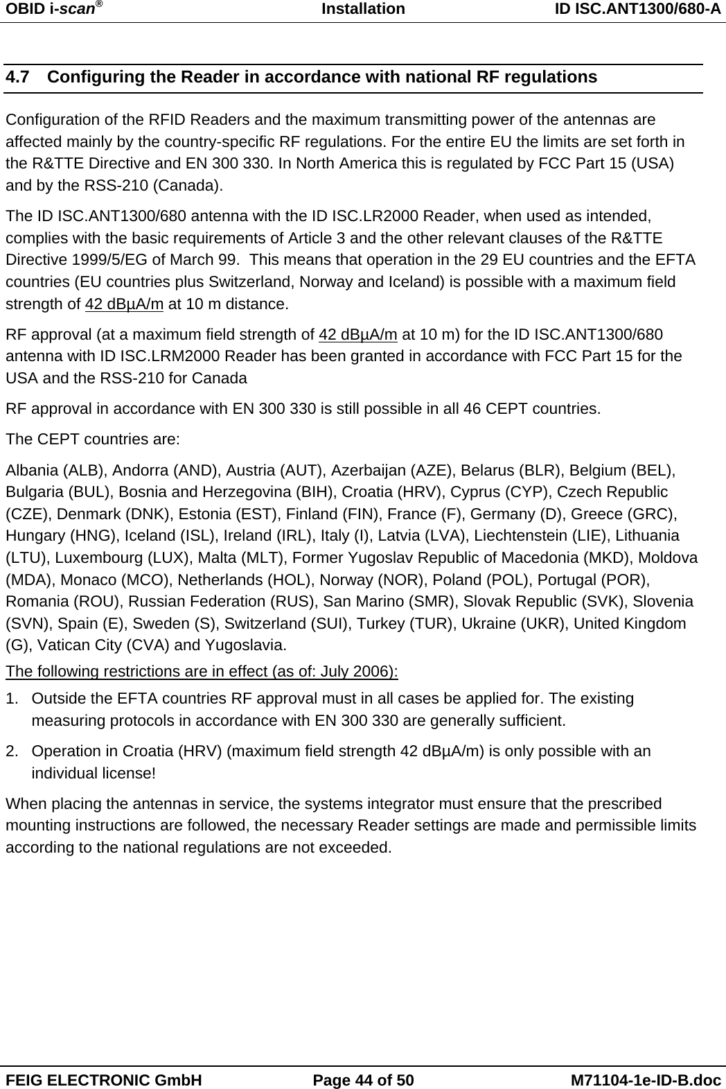
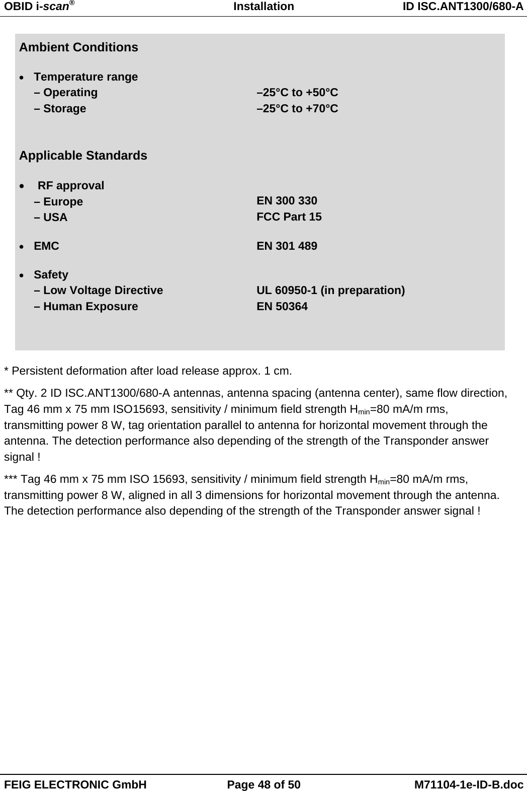
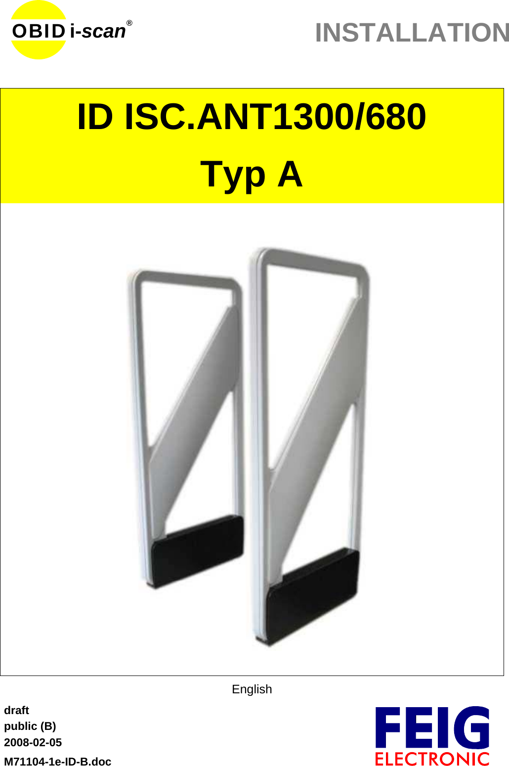
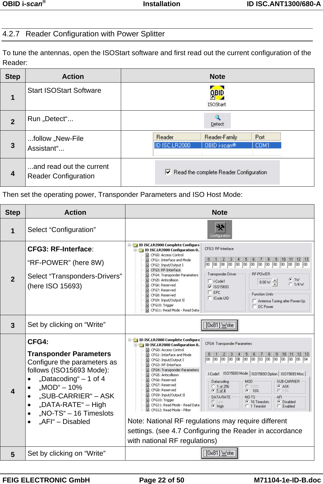
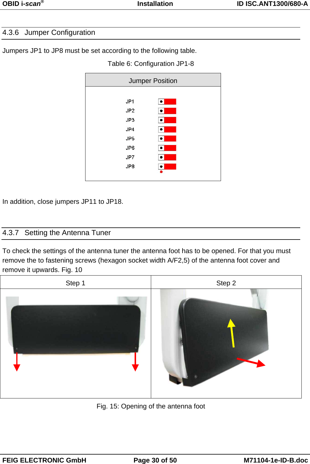
![OBID i-scan®Installation ID ISC.ANT1300/680-AFEIG ELECTRONIC GmbH Page 42 of 50 M71104-1e-ID-B.doc7To verify, read AFI byte byselecting[0x2B] Get SystemInformation](https://usermanual.wiki/Feig-Electronic/ANT1300680/User-Guide-900174-Page-41.png)