Feig Electronic ANT1300680 Security Gate User Manual M71104 1e ID B
Feig Electronic GmbH Security Gate M71104 1e ID B
Installation Manual
INSTALLATION
draft
public (B)
2008-02-05
M71104-1e-ID-B.doc
OBI
D
i-scan
®
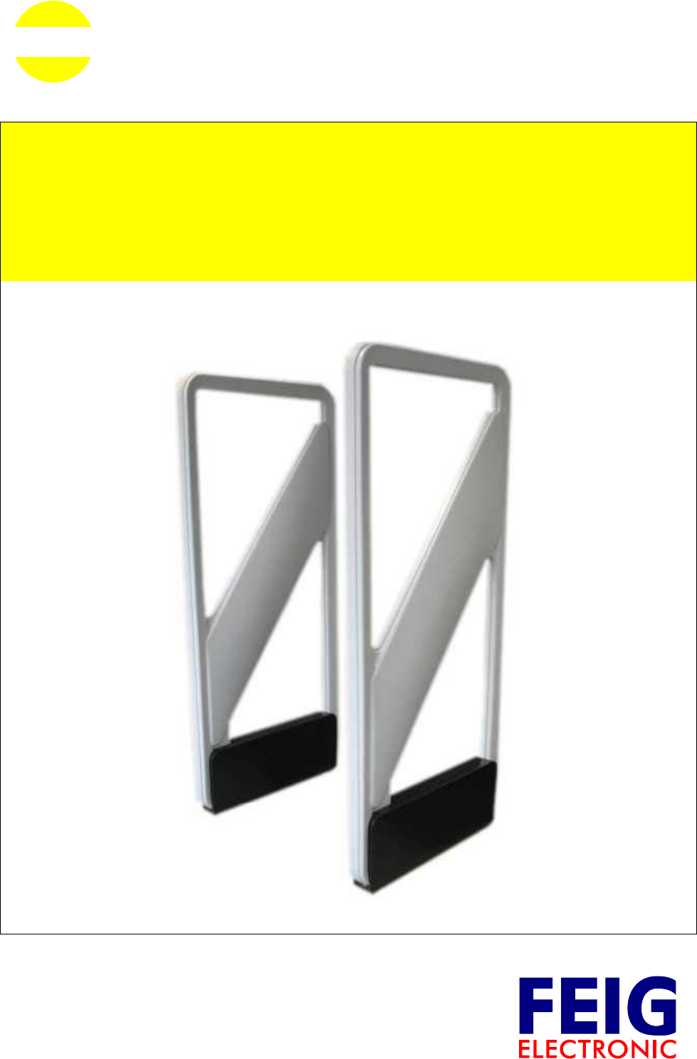
ID ISC.ANT1300/680
Typ A
English

OBID i-scan®Installation ID ISC.ANT1300/680-A
FEIG ELECTRONIC GmbH Page 3 of 50 M71104-1e-ID-B.doc
Note
© Copyright 2008 by
FEIG ELECTRONIC GmbH
Lange Strasse 4
D-35781 Weilburg-Waldhausen
Tel.: +49 6471 3109-0
http://www.feig.de
With the edition of this document, all previous editions become void. Indications made in this manual may be
changed without previous notice.
Copying of this document, and giving it to others and the use or communication of the contents thereof are
forbidden without express authority. Offenders are liable to the payment of damages. All rights are reserved
in the event of the grant of a patent or the registration of a utility model or design.
Composition of the information in this document has been done to the best of our knowledge. FEIG
ELECTRONIC GmbH does not guarantee the correctness and completeness of the details given in this
manual and may not be held liable for damages ensuing from incorrect or incomplete information. Since,
despite all our efforts, errors may not be completely avoided, we are always grateful for your useful tips.
The instructions given in this manual are based on advantageous boundary conditions. FEIG ELECTRONIC
GmbH does not give any guarantee promise for perfect function in cross environments and does not give
any guaranty for the functionality of the complete system which incorporates the subject of this document.
FEIG ELECTRONIC call explicit attention that devices which are subject of this document are not designed
with components and testing methods for a level of reliability suitable for use in or in connection with surgical
implants or as critical components in any life support systems whose failure to perform can reasonably be
expected to cause significant injury to a human. To avoid damage, injury, or death, the user or application
designer must take reasonably prudent steps to protect against system failures.
FEIG ELECTRONIC GmbH assumes no responsibility for the use of any information contained in this docu-
ment and makes no representation that they free of patent infringement. FEIG ELECTRONIC GmbH does
not convey any license under its patent rights nor the rights of others.
OBID® and OBID i-scan® are registered trademarks of FEIG ELECTRONIC GmbH.
I-CODE® is a registered trademark of Philips Electronics N.V.
Tag-itTM is a registered trademark of Texas Instruments Incorporated.

OBID i-scan®Installation ID ISC.ANT1300/680-A
FEIG ELECTRONIC GmbH Page 4 of 50 M71104-1e-ID-B.doc
Contents
1 Safety Instructions / Warning - Read before Start-Up ! 6
2 Performance Features of the ID ISC.ANT1300/680 Antennas 7
2.1 Available Antenna Types..............................................................................................7
3 Installation and Wiring 8
3.1 Dimensions of antenna.................................................................................................8
3.2 Mounting preparation...................................................................................................9
3.3 Installing the antenna .................................................................................................10
3.3.1 Drilling the Mounting Holes ...........................................................................................10
3.3.2 Installing the Antenna Base and Antenna Body ............................................................12
4 Typical Antenna Configuration (Gate Antenna with two Antennas) 13
4.1 Project Notes ...............................................................................................................13
4.2 Configuration and Setup using Antenna Type -A with power splitter....................15
4.2.1 Required Components ..................................................................................................15
4.2.2 Contents of the Gate- Integration- Kit ID ISC.ANT.GIK................................................16
4.2.3 Mounting of the components at the use of the Power Splitter......................................17
4.2.4 Configuration of a Gate antenna with power splitter......................................................19
4.2.5 Setting the Power Splitter..............................................................................................20
4.2.6 Setting the Antenna Tuner ............................................................................................20
4.2.7 Reader Configuration with Power Splitter......................................................................22
4.2.8 Tuning the Gate Antenna with Power Splitter................................................................24
4.3 Configuration and Setup using Antennas Type –A with Multiplexer .....................25
4.3.1 Required Components ..................................................................................................25
4.3.2 Mounting of the components at the use of the Multiplexer...........................................26
4.3.3 Configuration of a Gate antenna with Multiplexer..........................................................28
4.3.4 Setting the Multiplexer...................................................................................................29
4.3.5 DIP Switch Configuration ..............................................................................................29
4.3.6 Jumper Configuration ....................................................................................................30

OBID i-scan®Installation ID ISC.ANT1300/680-A
FEIG ELECTRONIC GmbH Page 5 of 50 M71104-1e-ID-B.doc
4.3.7 Setting the Antenna Tuner ............................................................................................30
4.3.8 Reader Configuration with Multiplexer...........................................................................32
4.3.9 Tuning the Gate Antenna with Multiplexer.....................................................................34
4.4 Testing the Gate Antenna...........................................................................................35
4.4.1 Checking the Noise Level..............................................................................................35
4.4.2 Reading a Serial Number ..............................................................................................36
4.4.3 Testing the performance ...............................................................................................36
4.5 Connecting and Setting the Alarm Kit (optional) .....................................................38
4.5.1 Installing the Alarm Indicators .......................................................................................38
4.5.2 Connecting the Indicators..............................................................................................38
4.5.3 Reader Setting for Indicators.........................................................................................39
4.5.4 Programming a Transponder with the AFI Byte ............................................................41
4.6 Activating Buffered Read Mode .................................................................................43
4.7 Configuring the Reader in accordance with national RF regulations ....................44
5 Technical Data 46
5.1 Antenna ID ISC.ANT1300/680- Type A......................................................................46
5.2 Approval.......................................................................................................................49
5.2.1 Europe (CE) ..................................................................................................................49
5.2.2 USA (FCC) and Canada (IC).........................................................................................50
5.2.3 USA (UL) .......................................................................................................................51

OBID i-scan®Installation ID ISC.ANT1300/680-A
FEIG ELECTRONIC GmbH Page 6 of 50 M71104-1e-ID-B.doc
1 Safety Instructions / Warning - Read before Start-Up !
• The device may only be used for the intended purpose designed by for the manufacturer.
• The operation manual should be conveniently kept available at all times for each user.
• Unauthorized changes and the use of spare parts and additional devices which have not been
sold or recommended by the manufacturer may cause fire, electric shocks or injuries. Such
unauthorized measures shall exclude any liability by the manufacturer.
• The liability-prescriptions of the manufacturer in the issue valid at the time of purchase are valid
for the device. The manufacturer shall not be held legally responsible for inaccuracies, errors,
or omissions in the manual or automatically set parameters for a device or for an incorrect
application of a device.
• Repairs may only be executed by the manufacturer.
• Installation, operation, and maintenance procedures should only be carried out by qualified
personnel.
• Use of the device and its installation must be in accordance with national legal requirements
and local electrical codes .
• When working on devices the valid safety regulations must be observed.
• Please observe that some parts of the device may heat severely.
• Before touching the device, the power supply must always be interrupted. Make sure that the
device is without voltage by measuring. The fading of an operation control (LED) is no indicator
for an interrupted power supply or the device being out of voltage!
• For installation and dismantling you should wear suitable safety gloves, because parts of an-
tenna housing could be sharp-edged.
CAUTION! The Antenna-Tuner and the Antenna conductor carry voltages up to
1000V.
Special advice for wearers of cardiac pacemakers:
• Although this device doesn't exceed the valid limits for electromagnetic fields you should keep
a minimum distance of 25 cm between the device and your cardiac pacemaker and not stay in
an immediate proximity of the reader’s antennas for any length of time.

OBID i-scan®Installation ID ISC.ANT1300/680-A
FEIG ELECTRONIC GmbH Page 7 of 50 M71104-1e-ID-B.doc
2 Performance Features of the ID ISC.ANT1300/680 Antennas
The ID ISC.ANT1300/680 Type A antenna is the version with dynamicTuning Board ID ISC.DAT
mounted. The Reader and Power-Splitter or Multiplexer are not included and had to be ordered
separately and then to be mounted into the antenna
Up to
- two antennas Type A with reader and power splitter or multiplexer as a single gate,
- three antennas Type A with reader and multiplexer as a double gate, or
- 4 - 8 antennas with reader and multiplexer as a multiple gate
can be operated.
Depending on the antenna configuration, one, two or all three read orientations of the Smart Tags
and various antenna spacing (gate widths) are possible.
The ID ISC.ANT1300/680 Type A is „figure-of-eight“ antenna with tuner and have been optimized
as transmitting and receiving antennas for the ID ISC.LR2000 Reader. It is however also possible
to operate them with other Readers at a transmission frequency of 13.56 MHz and an output
impedance of 50 Ω. The read ranges indicated in this document and the tuning procedures may
however then vary.
The antennas comprise the electrical antenna conductor, the housing, the ID ISC.DAT Dynamic
Antenna Tuner and the connection cable. The antennas are factory tuned to an impedance of 50 Ω
in a magnetically neutral environment at a distance of 95 cm. When installing in different ambient
conditions the antenna can be retuned using the “DATuningTool“ PC software. After tuning the
antennas will retain their settings as long as the ambient conditions remain unchanged.
The antennas can be used for detecting both product and persons. It is suitable for installation
indoors or outdoors if weather-protected.
2.1 Available Antenna Types
The following Antennas are currently available:
Antenna Type Description
ID ISC.ANT1300/680-A Antenna with dynamic tuning board ID ISC.DAT
ID ISC.ANT-GIK Mounting material and cables
for Reader, Power Splitter or Multiplexer
ID ISC.ANT-GAK Acoustic alarm signal with mounting material
Table 1: Available Antenna Types
OBID i-scan®Installation ID ISC.ANT1300/680-A
FEIG ELECTRONIC GmbH Page 8 of 50 M71104-1e-ID-B.doc
3 Installation and Wiring
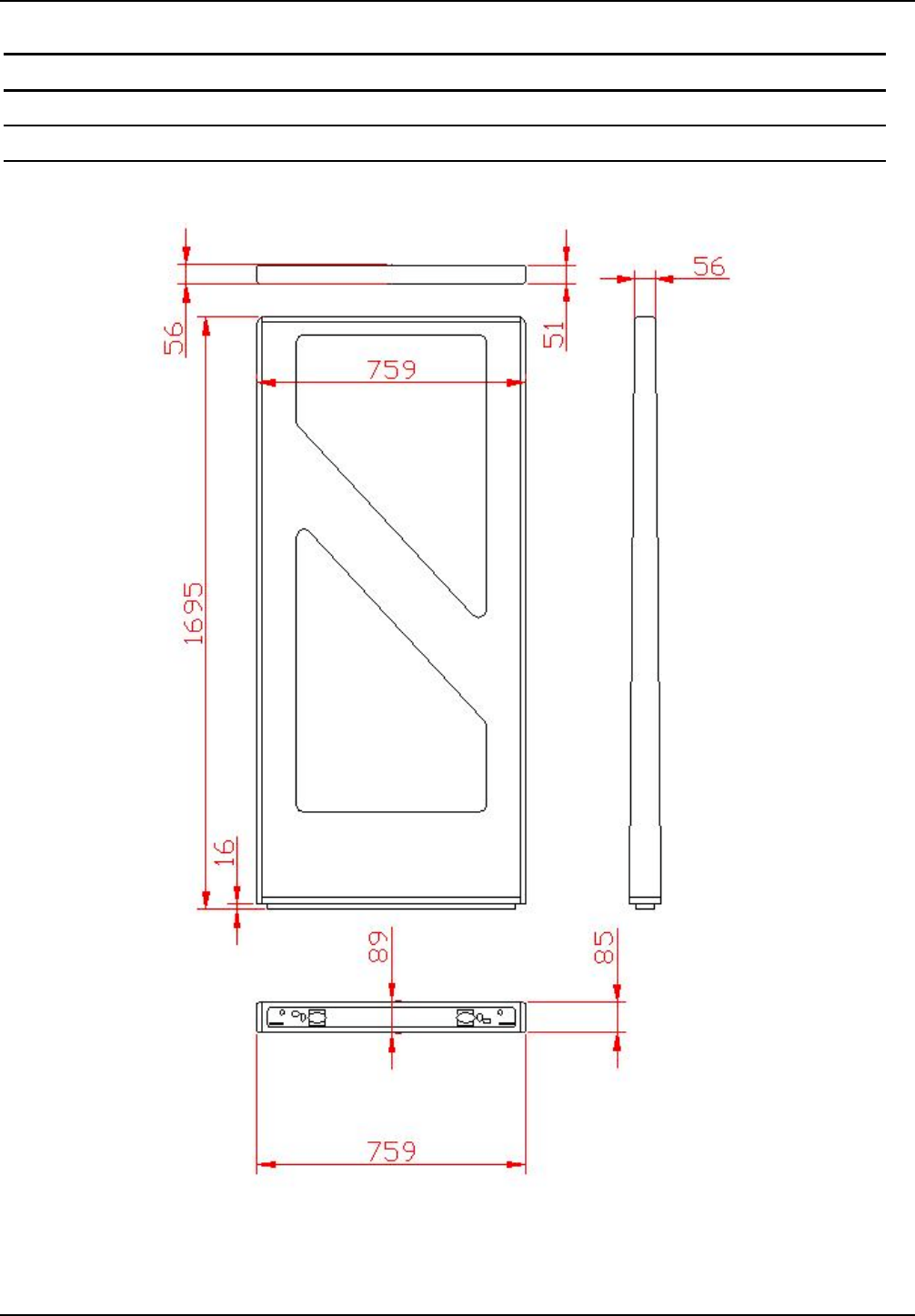
3.1 Dimensions of antenna
The outside dimensions of the antenna are shown in Fig. 1
Fig. 1: Antenna outside dimensions
All dimensions are in mm with general tolerance to ISO 2768 m (mean).
OBID i-scan®Installation ID ISC.ANT1300/680-A
FEIG ELECTRONIC GmbH Page 9 of 50 M71104-1e-ID-B.doc
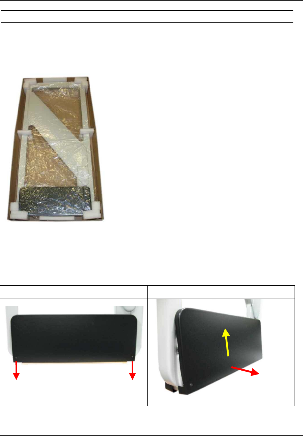
3.2 Mounting preparation
For assembly the antenna must be carefully unpacked. This is done as described in the following
steps:
1. Place the packed antenna on the floor with the top side facing up. Carefully open the box and
then remove the antenna.
Fig. 2: Antenna in its packaging
2. After that the antenna has to be placed carefully again on the floor. Now you must remove the
to fastening screws (hexagon socket width A/F2,5) of the antenna foot cover and remove it
upwards. Fig. 3
Step 1 Step 2
Fig. 3: Opening the antenna foot
OBID i-scan®Installation ID ISC.ANT1300/680-A
FEIG ELECTRONIC GmbH Page 10 of 50 M71104-1e-ID-B.doc
3.3 Installing the antenna
Notes:
Before installing the antennas please read 4.1 Project Notes . The spacing of the antennas
comprising a gate depends on the antenna configuration.
If multiple antennas or gates are connected to different Readers, a minimum separation of
8 m must be kept between the antennas or gates. For shorter distances (1 m – 8 m) the
Readers must be multiplexed. Below a distance of 1.5 m the antennas must also be shielded
from each other. Otherwise the Reader range will be significantly reduced. The antennas
must have a minimum distance of 20 cm from all larger metal parts! At a distance of less
than 50 cm between the antenna and metal parts the Reader range will be significantly
reduced.
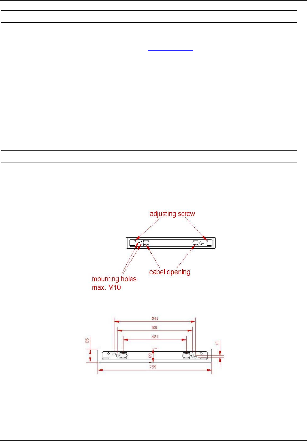
3.3.1 Drilling the Mounting Holes
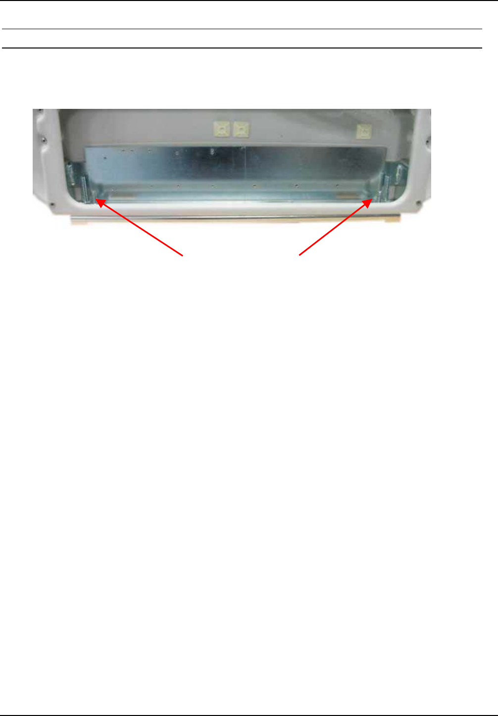
If the position of the antennas has been marked or determined, the antenna foot c, which is to be
used as a hole template, can be used to mark and drill the mounting holes and the holes for the
cable entry. The dimensions are shown in Fig. 4:
Fig. 4: Floor plate dimensions c
All dimensions are in mm with general tolerance to ISO 2768 m (middle).
OBID i-scan®Installation ID ISC.ANT1300/680-A
FEIG ELECTRONIC GmbH Page 11 of 50 M71104-1e-ID-B.doc
The size and type of the screw anchors depends considerably on the strength of the base or floor.
The anchors should be capable of withstanding a permissible load of at least 5 kN per anchor for
all load directions (e.g. for concrete floor Hilti HVA anchors with HAS-(E) M8 threaded rod or Hilti
HIS-N M8 (5/16”) threaded inserts). The size of the mounting holes in the antenna is 10 mm (.39”).
The length of the anchors or bolts should be selected such that they extend at least 50 mm (2.0”)
and a maximum of 65 mm (2.6”) from the floor.
Please follow the mounting instructions of the anchor manufacturer!
Two cable openings are provided for the necessary connection cable (see Fig. 4). The cable
openings are dimensioned such that up to 10 cables having a diameter of 6 mm can be passed
through each opening.
We recommend routing the antenna cables through the cable opening on the Power-Splitter or
Multiplexer side. All other cables such as the supply voltage and multiplexing cable should be
routed through the cable opening on the Reader side.
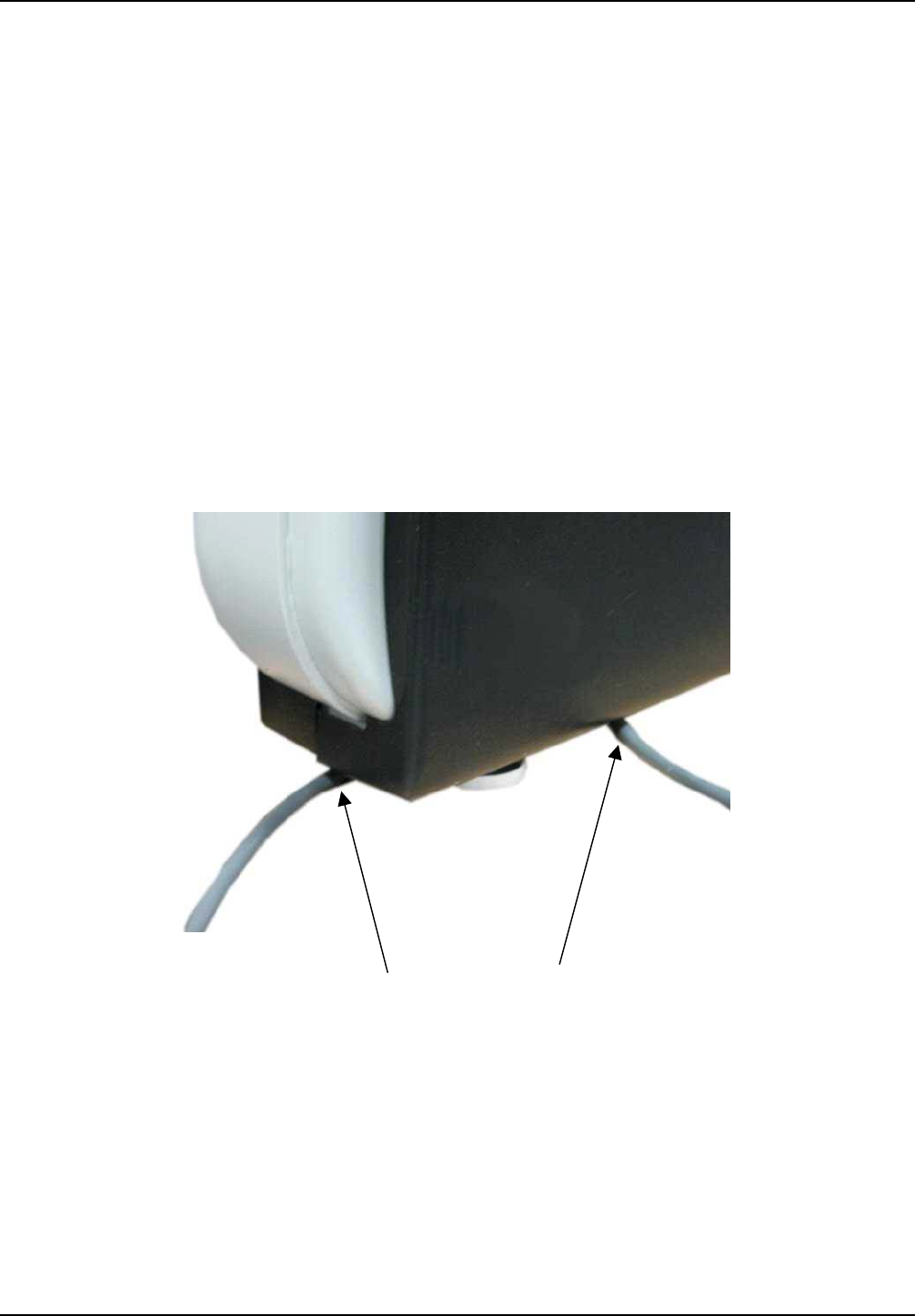
Alternatively the cables can be routed at the sides of the antenna bas like shown in Fig. 5
Fig. 5 Cable routing at the antenna sides
OBID i-scan®Installation ID ISC.ANT1300/680-A
FEIG ELECTRONIC GmbH Page 12 of 50 M71104-1e-ID-B.doc
3.3.2 Installing the Antenna Base and Antenna Body
The antenna will be screwed on the floor. Use the adjusting screws (Fig. 6) to align the antenna
vertically.
Adjusting screws (hexagon socket width A/F5)
Fig. 6: Attaching and aligning the antenna
OBID i-scan®Installation ID ISC.ANT1300/680-A
FEIG ELECTRONIC GmbH Page 13 of 50 M71104-1e-ID-B.doc
4 Typical Antenna Configuration (Gate Antenna with two Antennas)
The standard configuration of a gate with three-dimensional tag orientation consists of two
ID ISC.ANT1300/680 Type A with reader and power splitter or multiplexer. If a tag moves through
the gate horizontally, it can be read at lease once. This ensures high reliability of the antenna
system.
4.1 Project Notes
The antenna configuration described allows detection of a tag moving horizontally through the
capture area of the gate. The tag orientation is non-critical. The tags are detected along a
horizontal axis of motion in certain regions within the antennas. The area of detection depends on
the tag orientation.
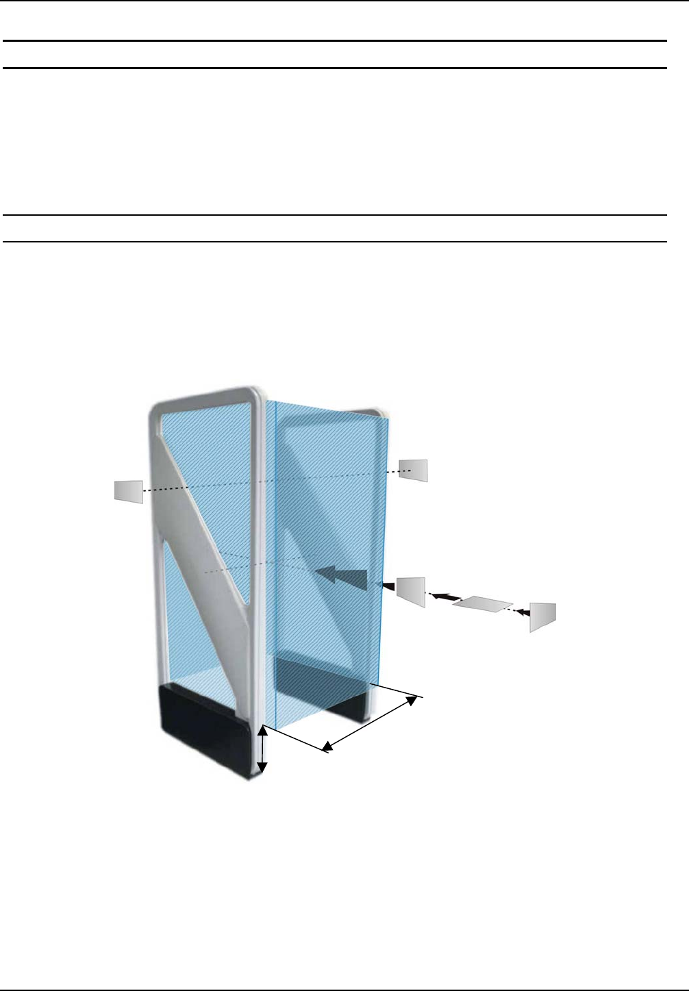
The size of the three-dimensional capture area of the antennas is shown in the sketch below.
Fig. 7: Capture area and tag orientation
Notes:
Note that the entire capture area of the antenna is larger than the three-dimensional area
shown in the drawing. This means there are tag orientations in which the tag can be
detected outside the capture area.
GD
10
cm

OBID i-scan®Installation ID ISC.ANT1300/680-A
FEIG ELECTRONIC GmbH Page 14 of 50 M71104-1e-ID-B.doc
If multiple gates are arranged with short distances between each other, these will mutually
interfere with each other. The Readers for the respective gates must then be synchronized.
To achieve three-dimensional capture of the tag in the capture area drawn above, the following
conditions must be met:
- The gate distance GD depends on the antenna configuration (see Table 2: Design notes).
- The tags should be at least ISO card size (46 mm x 75 mm).
- The activation field strength of the tags should be less than or equal to 80 mA/m.
- The distance from tag to tag should be greater than 10 cm. If the tag to tag distance is reduced,
the gate distance GD must be reduced correspondingly. This applies in particular to distances
under 5 cm.
- The maximum number of tags (serial number or data) depends on the traverse speed with
which the tags are brought through the capture area of the gate (see Table 2: Design notes).
The number of tags may be increased in the gate distance GD is correspondingly reduced and
the maximum speed adjusted accordingly.
- The antenna should be at least 50 cm from metal parts.
- There should be no interference of the Reader from other electrical devices in the environment.
The Noise Level difference should be less than 30 mV.
- The ID ISC.LR2000 Reader should be set to an RF power of 8 watts.
- When using ISO 15693 transponders, the Readers should be set as described in 4.2.7 Reader
Configuration with Power Splitter or 4.3.8 Reader Configuration with Multiplexer.
- If multiple gates are operated at the same time at a distance of less than 8 m, the Readers
must by synchronized. See Application Note Synchronizing RFID LongRange Readers using
the digital in-/outputs (N11200-1e-ID-B.pdf).
Table 2: Design notes
Antenna Type A
With reader and
power splitter
Antenna Type A
With reader and
multiplexer
Gate distance GD ≤ 90 cm ≤ 95 cm
Number of tags at traverse
speed 1 m/s
- Read serial number
- Read data
16
8
16
8

OBID i-scan®Installation ID ISC.ANT1300/680-A
FEIG ELECTRONIC GmbH Page 15 of 50 M71104-1e-ID-B.doc
4.2 Configuration and Setup using Antenna Type -A with power splitter
4.2.1 Required Components
To construct the gate you need the following components:
- Qty. 2 Antenna ID ISC.ANT1300/6800 Type A
- Qty. 1 Reader module ID ISC.LR2000-A-M
- Qty. 1 Power splitter module ID ISC.ANT-PS-BM
- Qty. 1 Gate integration kit ID ISC.ANT.GIK
- Qty. 1 power supply ID ISC.NET24-B
- Power cable, interface cable and connection cable for the DC power supplies (2-wire,
twisted)
- Mounting materials (screws, anchors)
Optional:
- Qty. 1 Alarm Kit ID ISC.ANT.GAK
To configure the Reader you will need the software
- ISOStart Version 7.01 or higher
and for tuning the antennas the service software
- DATuningTool Version 1.00 or higher
on a personal computer running under Microsoft® Windows®. The service software is included on
the OBID i-scan® CD obtained from FEIG ELECTRONIC GmbH or can be downloaded on the
Download Area of the Homepage www.feig.de.
OBID i-scan®Installation ID ISC.ANT1300/680-A
FEIG ELECTRONIC GmbH Page 16 of 50 M71104-1e-ID-B.doc
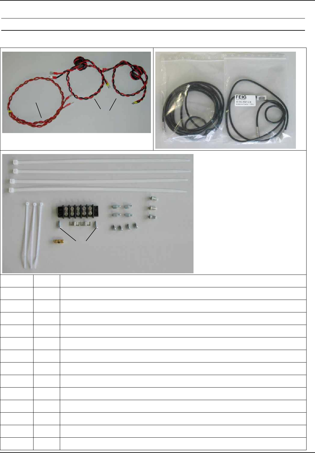
4.2.2 Contents of the Gate- Integration- Kit ID ISC.ANT.GIK
The following parts are contents of the Gate- Integration- Kit .
Position Qty. Name / Use
1. 1 DC- cable relay / Connection Buzzer – Relay Output – 24V
2. 2 DC-cable Reader, PS, Mux / DC-Connection to Terminal block – Reader, PS or Mux
3. 1 3,65m coaxial cable/ HF- Connection Reader – Mux (just at the use of Mux)
4. 1 1,35m coaxial cable / HF- Connection Reader – PS or Mux
5. 4 Cable tie 4,8x280mm / tie together of the coaxial cables
6. 3 Cable tie 2,5x105mm / Mounting of the torrid cores of the DC-cables and the relay
7. 1 SMA adapter female-female / Connection of 1,35m with 3,65m coaxial cable with Mux
8. 1 Terminal block 5x 2pin / Connection DC - cables
9. 2 Bridge of Terminal block / Connection of the terminals GND and 24VDC
10. 2 Screw M3x10 / Mounting Terminal block into the antenna foot
11. 4 Hexagon spacer bolt M3x6 / Mounting PS or Multiplexer into the antenna foot
12. 4 Screw M3x6 / Mounting PS or Multiplexer into the antenna foot
13. 3 Screw M4x8 / Mounting Reader into the antenna foot
1.
2.
4.
3.
5.
6.
7.
8.
9.
10.
11.
12.
13.
OBID i-scan®Installation ID ISC.ANT1300/680-A
FEIG ELECTRONIC GmbH Page 17 of 50 M71104-1e-ID-B.doc
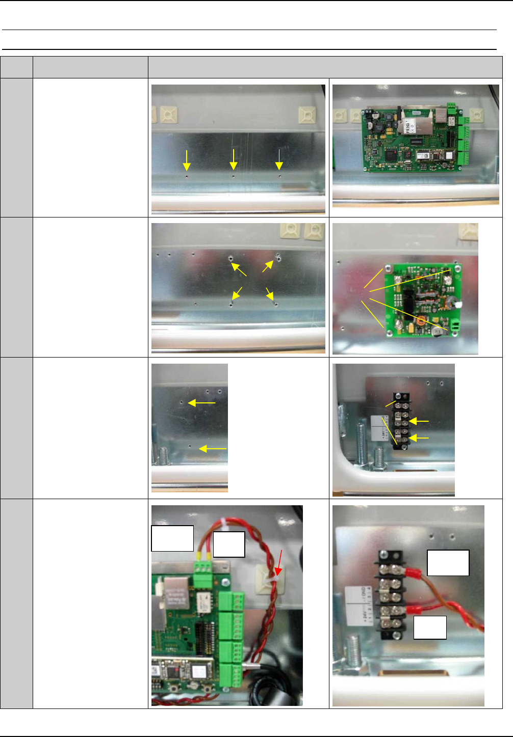
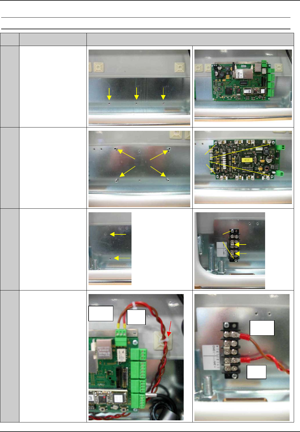
4.2.3 Mounting of the components at the use of the Power Splitter
Step Action Note
1Mounting of the
reader with the screw
M4x8 Pos.13
2Mounting of the
Power Splitter with
the hexagon spacer
bolts M3x6 Pos.11
and the screws M3x6
Pos.12
3Mounting of the Ter-
minal block Pos.8
with the screws
M3x10 Pos.10 and
connection of the
terminals 1+2 (+24V)
and 3+4 (GND) with
the bridges. Pos.9
4Mounting of the relay
cable Pos.1 with
1 piece of cable tie
2,5x105mm Pos.6
Red wire to Com and
Brown wire to NO of
X9 Reader, Red wire
to 2 and Black wire to
5 of terminal block
11.
12.
9.
10.
Brown
Red
Brown Red 6.
X9
OBID i-scan®Installation ID ISC.ANT1300/680-A
FEIG ELECTRONIC GmbH Page 18 of 50 M71104-1e-ID-B.doc
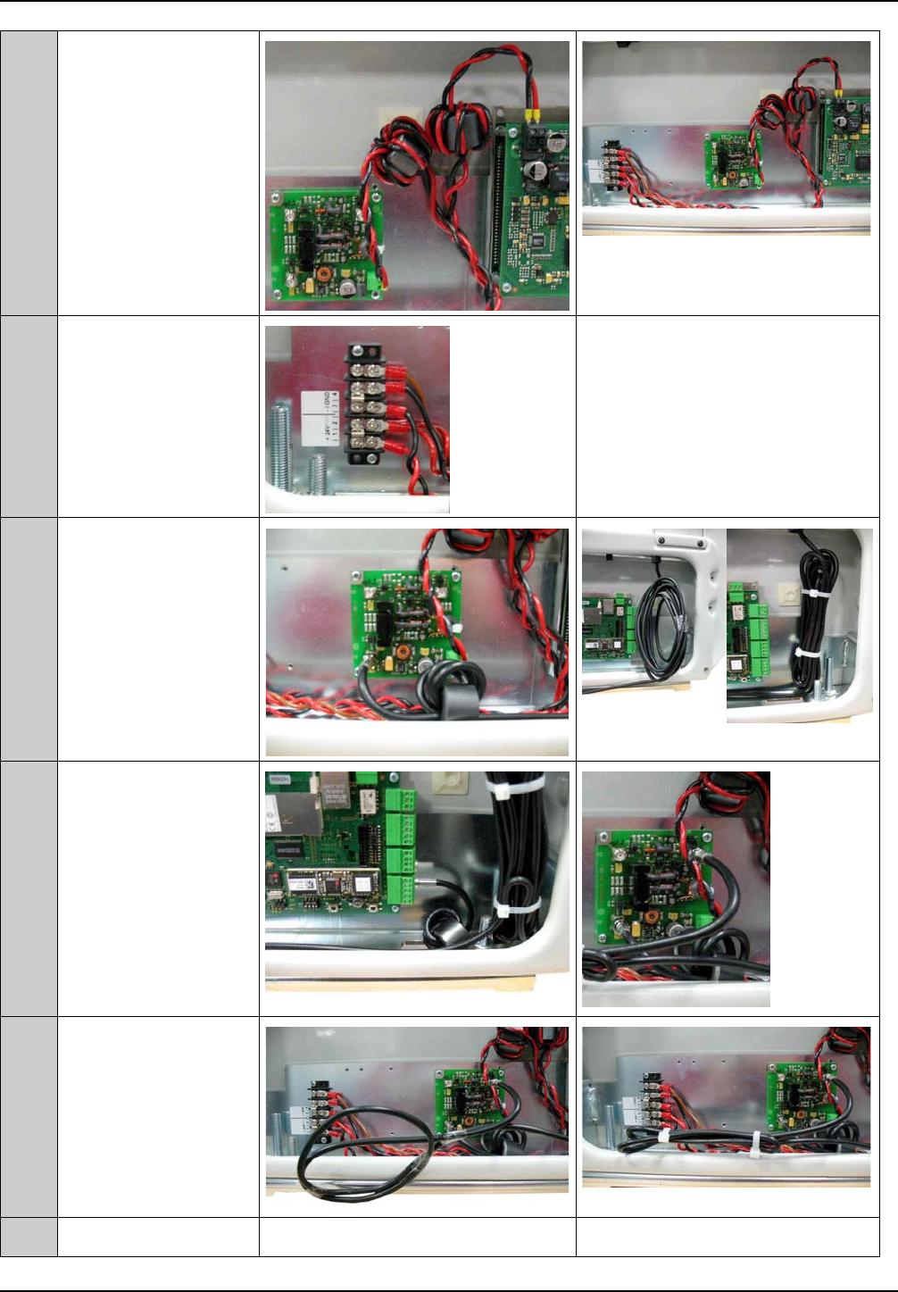
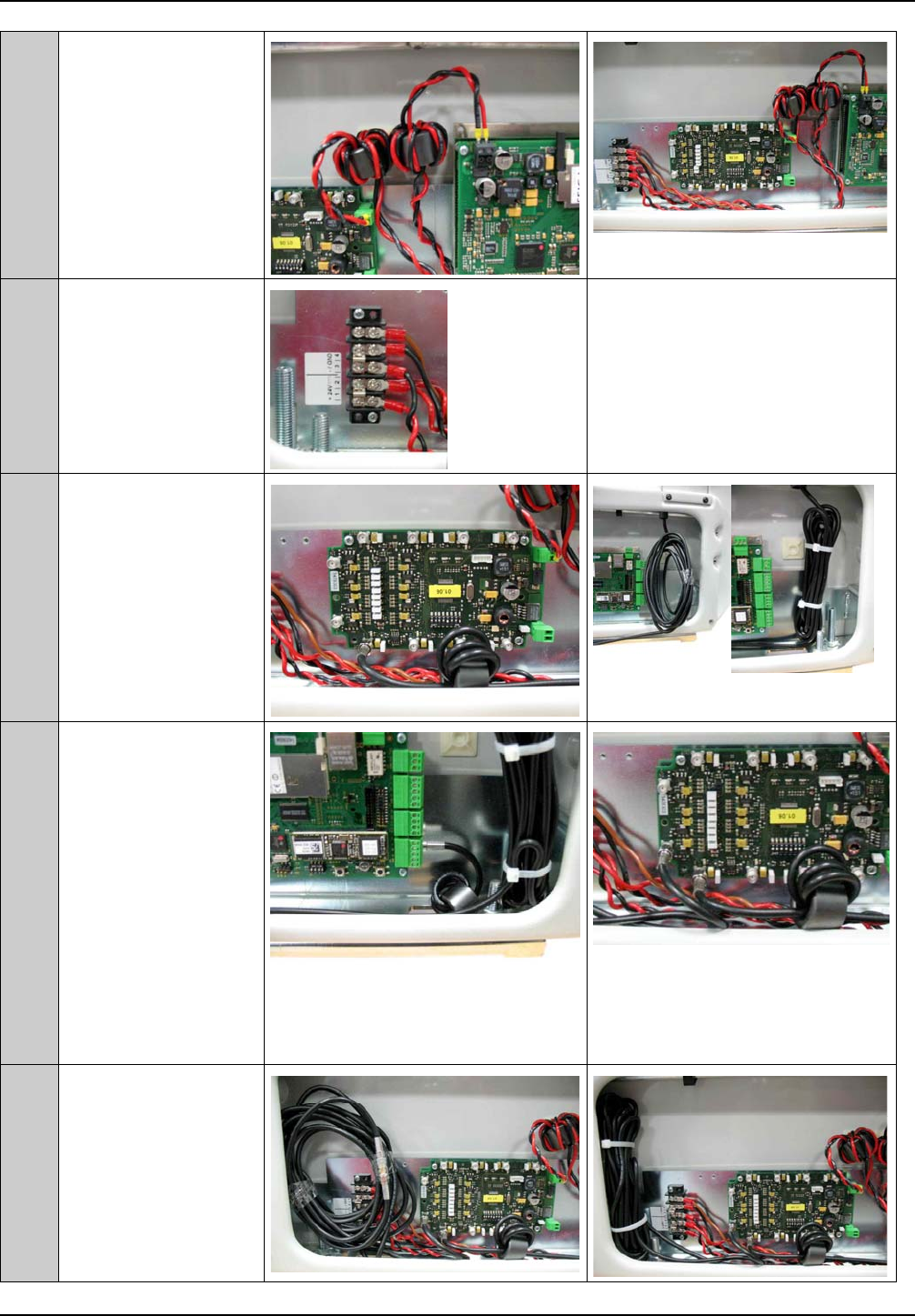
5Mounting of the DC-
cables Pos.2 of the
readers and of the
PS with 2 pieces of
cable tie 2,5x105mm
Pos.6
Attention! Take care
of polarity.
6Connect DC- cables
to Terminal block
Red wire to terminal
1+2 (+24V), Black
wire to terminal 3+4
(GND)
. Attention! Take care of polarity.
7Connect the antenna
cable with X3 of PS.
Wind up the rest of
the cable to loops
and tied it together
with 2 pieces of cable
tie 4,8x280mm Pos.5
8Mounting of the
1,35m coaxial cable
between X1 Reader
and X1 PS. Mount
the torrid from the
reader attachment
approx. 10cm with 4
turns before the
reader.
9Wind up the rest of
the cable to loops
and tied it together
with 2 pieces of cable
tie 4,8x280mm Pos.5
and place it in the
antenna foot.
X
1
X3
X1
OBID i-scan®Installation ID ISC.ANT1300/680-A
FEIG ELECTRONIC GmbH Page 19 of 50 M71104-1e-ID-B.doc
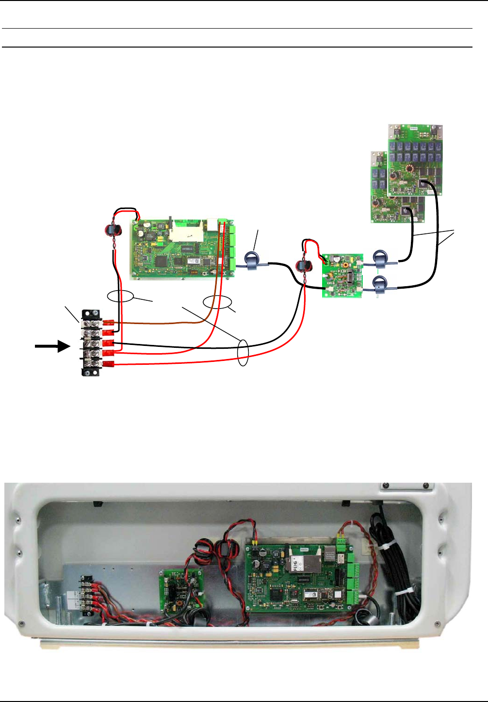
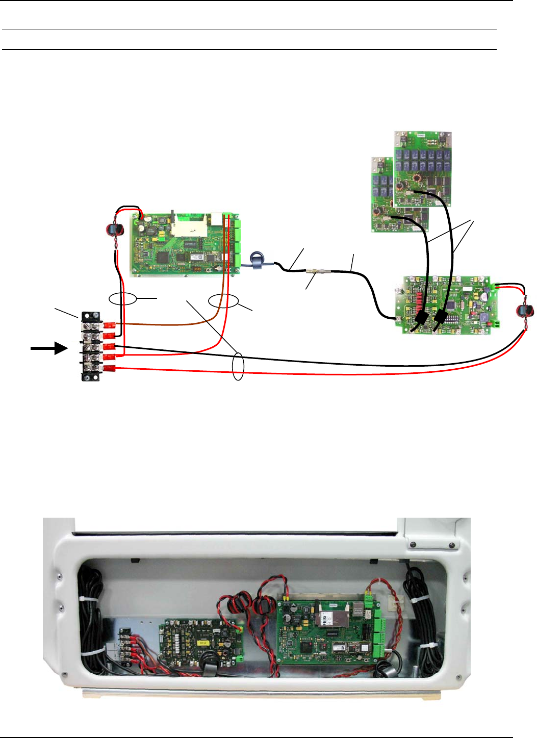
4.2.4 Configuration of a Gate antenna with power splitter
Connect the components as shown in Fig. 8
Fig. 8: Component connection for a standard Gate Type A with power splitter
The coax cables have fixed lengths and may not be shortened and therefore need to be tied into
small loops (see Fig. 9). Tie all cables as far away from the antenna conductor as possible. The
cables must never be allowed to contact the aluminum tube.
Fig. 9: Tying the cables
X2
X3
X1
3,60m
2 Tuning boards of
antennas ID ISC.ANT1300/680
Power Splitter
ID ISC.ANT.PS-BM
X1
1,35m X4
Torrid core
Long Range Reader
ID ISC.LRM2000
IN1
X9, Pin1+3
DC Power supply
24V
Pos.1
Pos.2
Pos.4
Pos.8
OBID i-scan®Installation ID ISC.ANT1300/680-A
FEIG ELECTRONIC GmbH Page 20 of 50 M71104-1e-ID-B.doc
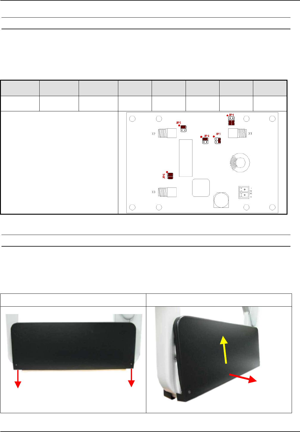
4.2.5 Setting the Power Splitter
Set the jumpers on the Power Splitter as shown Table 3:Power Splitter setting. More information
about setting the ID ISC.ANT.PS-BM Power Splitter can be found in the corresponding installation
manual (M40402-xde-ID-B).
Table 3:Power Splitter setting
Trans-
former Power
Splitter Phase
shifter JP1 JP3 JP4 JP5 JP6
not used X X 3-5
4-6 2-4 1-2 1-2 1-2
3-4
Power Splitter with 90° phase shifter
X1: Reader
X2: Antenna
X3: Antenna
X4: 12-24V DC for Antenna with dyn.
antenna tuner ID ISC.DAT
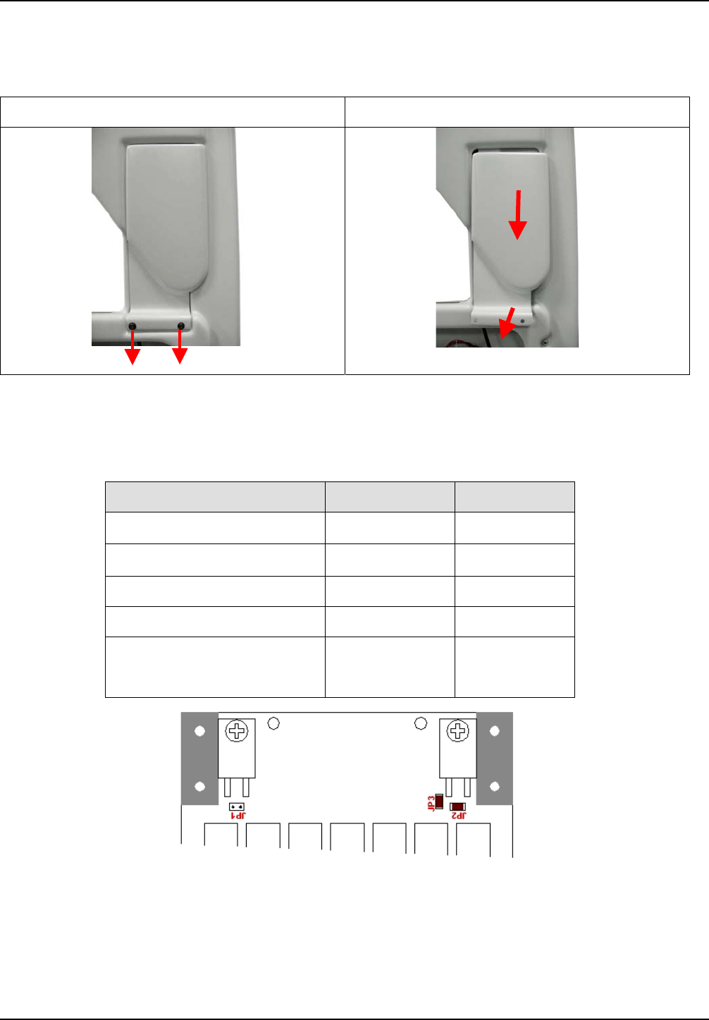
4.2.6 Setting the Antenna Tuner
To check the settings of the antenna tuner the antenna foot has to be opened. For that you must
remove the to fastening screws (hexagon socket width A/F2,5) of the antenna foot cover and
remove it upwards. Fig. 10
Step 1 Step 2
Fig. 10: Opening of the antenna foot
OBID i-scan®Installation ID ISC.ANT1300/680-A
FEIG ELECTRONIC GmbH Page 21 of 50 M71104-1e-ID-B.doc
Now you must remove the to fastening screws (hexagon socket width A/F2,5) of the antenna tuner
cover and remove it upwards. Fig. 11
Step 3 Step 4
Fig. 11 Removing the antenna tuner cover
The ID ISC.ANT1300/680-A antennas are factory set as follows:
Table 4: Jumper settings for Antenna Tuner
Function Jumper Position
1Ω Q resistor JP1 open
2Ω Q resistor JP2 closed
Antenna switch JP3 closed
Capacitor C1 JP 11,12,13,14 open
Capacitor C2 JP 21,22,25,26
JP 23,24
open
closed
Verify these settings. More on setting the ID ISC.DAT antenna tuner can be found in the
corresponding installation manual (M40401-xde-ID-B).
OBID i-scan®Installation ID ISC.ANT1300/680-A
FEIG ELECTRONIC GmbH Page 22 of 50 M71104-1e-ID-B.doc
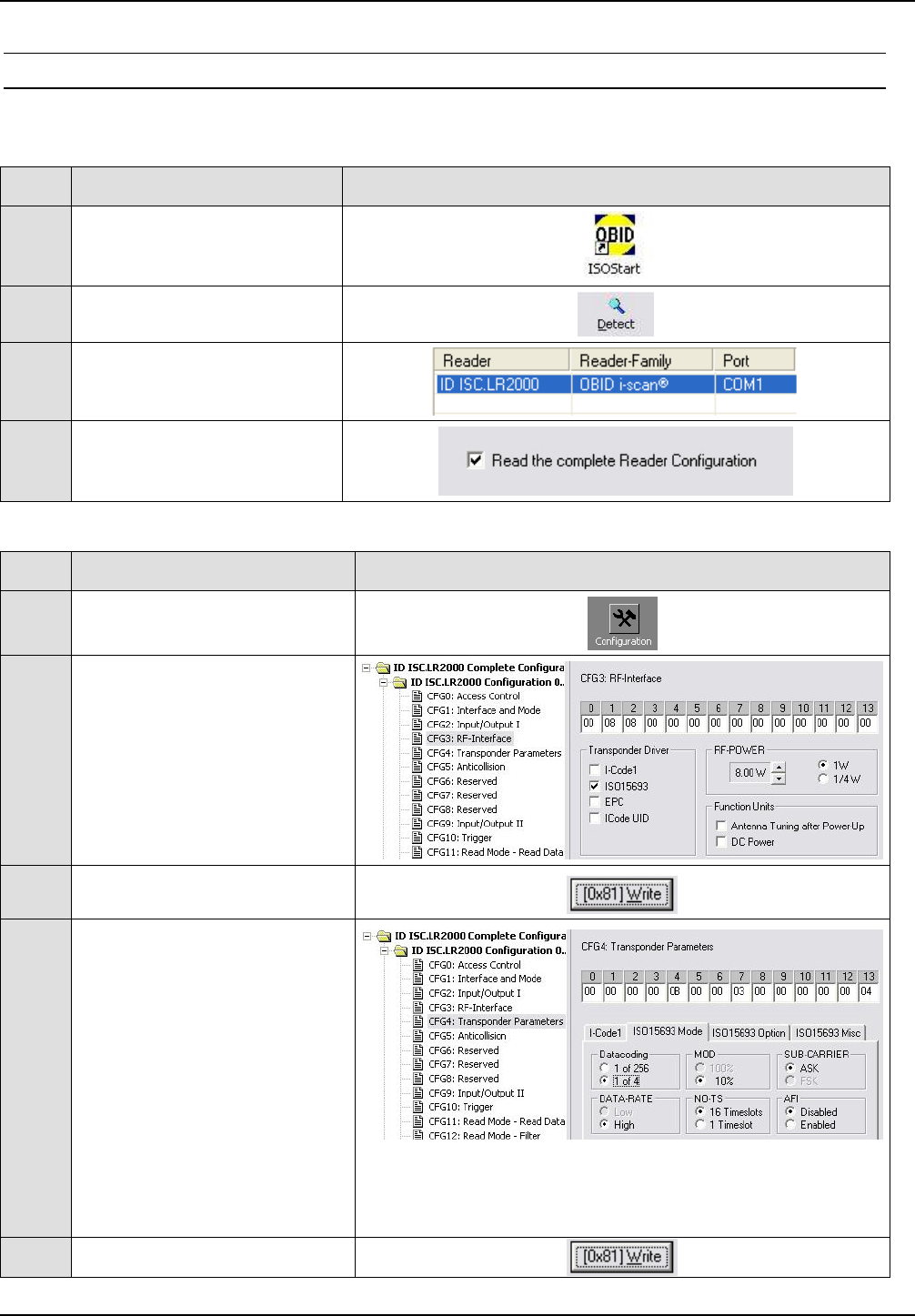
4.2.7 Reader Configuration with Power Splitter
To tune the antennas, open the ISOStart software and first read out the current configuration of the
Reader:
Step Action Note
1Start ISOStart Software
2Run „Detect“...
3...follow „New-File
Assistant“...
4...and read out the current
Reader Configuration
Then set the operating power, Transponder Parameters and ISO Host Mode:
Step Action Note
1Select “Configuration”
2
CFG3: RF-Interface:
“RF-POWER” (here 8W)
Select “Transponders-Drivers”
(here ISO 15693)
3Set by clicking on “Write”
4
CFG4:
Transponder Parameters
Configure the parameters as
follows (ISO15693 Mode):
• „Datacoding“ – 1 of 4
• „MOD“ – 10%
• „SUB-CARRIER“ – ASK
• „DATA-RATE“ – High
• „NO-TS“ – 16 Timeslots
• „AFI“ – Disabled Note: National RF regulations may require different
settings. (see 4.7 Configuring the Reader in accordance
with national RF regulations)
5Set by clicking on “Write”
OBID i-scan®Installation ID ISC.ANT1300/680-A
FEIG ELECTRONIC GmbH Page 23 of 50 M71104-1e-ID-B.doc
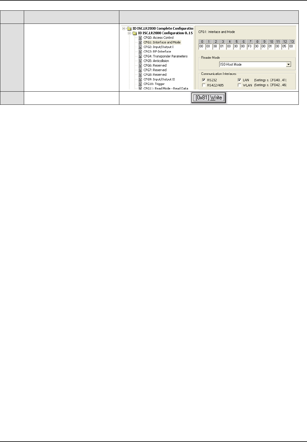
Step Action Note
6
CFG1: Interface and Mode
To tune, activate “ISO-Host
Mode”
7Set by clicking on “Write”
OBID i-scan®Installation ID ISC.ANT1300/680-A
FEIG ELECTRONIC GmbH Page 24 of 50 M71104-1e-ID-B.doc
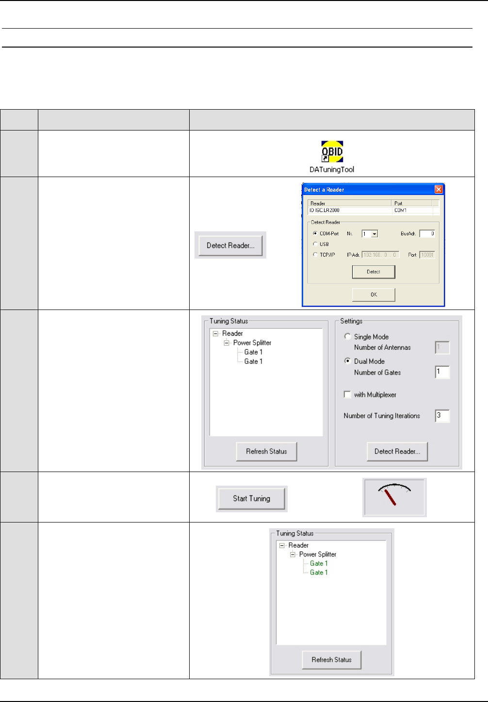
4.2.8 Tuning the Gate Antenna with Power Splitter
Before tuning the Gate Antenna you must quit the ISOStart software. Then the gate may be tuned
according to the following sequence:
Step Action Note
1Start “DATuningTool”
Software
2
Click on “Detect Reader...”
button and then “Detect” on
the selected interface (COM-
Port 1)
3
Use „Settings“ to enter the
configuration:
Dual Mode,
Number of Gates 1
Number of Tuning Iterations 3
4
Activate „Start Tuning“ and
wait until the tuning process is
ended. ... ...
5
After each tuning pass the
current tuning status is
displayed.
After successful tuning both
antennas for „Gate 1“ are
shown in green.
After successful tuning close the DATuningTool again.

OBID i-scan®Installation ID ISC.ANT1300/680-A
FEIG ELECTRONIC GmbH Page 25 of 50 M71104-1e-ID-B.doc
4.3 Configuration and Setup using Antennas Type –A with Multiplexer
4.3.1 Required Components
To construct the gate you need the following components:
- Qty. 2 Antenna ID ISC.ANT1300/680 Type A
- Qty. 1 Reader module ID ISC.LR2000-A-M
- Qty. 1 Multiplexer module ID ISC.ANT.MUX-A-M
- Qty. 1 Gate integration kit ID ISC.ANT.GIK
- Qty. 1 power supply ID ISC.NET24-B
- Power cable, interface cable and connection cable for the DC power supplies (2-wire,
twisted)
- Mounting materials (screws, anchors)
Optional:
- Qty. 1 Alarm Kit ID ISC.ANT.GAK
To calibrate the Reader you will need the software
- ISOStart Version 7.01 or higher
and for tuning the antennas the service software
- DATuningTool Version 1.00 or higher
on a personal computer running under Microsoft® Windows®. The service software is included on
the OBID i-scan® CD obtained from FEIG ELECTRONIC GmbH or can be downloaded at the
Download Area of the Homepage www.feig.de.
OBID i-scan®Installation ID ISC.ANT1300/680-A
FEIG ELECTRONIC GmbH Page 26 of 50 M71104-1e-ID-B.doc
4.3.2 Mounting of the components at the use of the Multiplexer
Step Action Note
1Mounting of the
reader with the screw
M4x8 Pos.13
2Mounting of the Mul-
tiplexer with the
hexagon spacer bolts
M3x6 Pos.11 and the
screws M3x6 Pos.12
3Mounting of the Ter-
minal block Pos.8
with the screws
M3x10 Pos.10 and
connection of the
terminals 1+2 (+24V)
and 3+4 (GND) with
the bridges. Pos.9
4Mounting of the relay
cable Pos.1 with
1 piece of cable tie
2,5x105mm Pos.6
Red wire to Com and
Brown wire to NO of
X9 Reader, Red wire
to 2 and Black wire to
5 of terminal block
11. 12.
9.
10.
Brown
Red
Brown Red 6.
X9
OBID i-scan®Installation ID ISC.ANT1300/680-A
FEIG ELECTRONIC GmbH Page 27 of 50 M71104-1e-ID-B.doc
5Mounting of the DC-
cables Pos.2 of the
readers and of the
Multiplexer with 2
pieces of cable tie
2,5x105mm Pos.6
Attention! Take care
of polarity.
6Connect DC- cables
to Terminal block
Red wire to terminal
1+2 (+24V), Black
wire to terminal 3+4
(GND)
. Attention! Take care of polarity.
7Connect the antenna
cable with Out 1 of
Multiplexer. Wind up
the rest of the cable
to loops and tied it
together with 2
pieces of cable tie
4,8x280mm Pos.5
8Mounting of the co-
axial cable between
X1 Reader and IN1
Multiplexer. Connect
the 1,35m and the
3,65m cable using
the SMA Adapter
Pos.7. Mount the
torrid from the reader
attachment approx.
10cm with 4 turns
before the reader.
9Wind up the rest of
the cable to loops
and tied it together
with 2 pieces of cable
tie 4,8x280mm Pos.5
and place it in the
antenna foot.
X
1
OUT1
IN1
OBID i-scan®Installation ID ISC.ANT1300/680-A
FEIG ELECTRONIC GmbH Page 28 of 50 M71104-1e-ID-B.doc
4.3.3 Configuration of a Gate antenna with Multiplexer
Connect the components as shown in Fig. 12.
Fig. 12: Connecting the components for a gate consisting of Type A with multiplexer
The coax cables have fixed lengths and may not be shortened and therefore need to be tied into
small loops (see Fig. 13:Tying the cables). Tie all cables as far away from the antenna conductor
as possible. The cables must never be allowed to contact the aluminum tube.
Fig. 13:Tying the cables
DC Power supply
24V
X2
X3
3,60m
2 Tuning boards of
antennas ID ISC.ANT1300/680
Multiplexer
ID ISC.ANT.MUX-A-M
Long Range Reader
ID ISC.LRM2000
X1
1,35m
IN1 OUT1
OUT2
3,60m
X1
Torrid core
X9, Pin1+3
Pos.8 Pos.2
Pos.1
Pos.4 Pos.3
Pos.7
OBID i-scan®Installation ID ISC.ANT1300/680-A
FEIG ELECTRONIC GmbH Page 29 of 50 M71104-1e-ID-B.doc
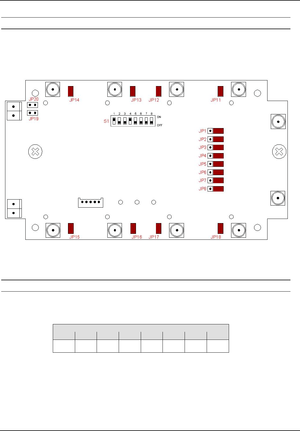
4.3.4 Setting the Multiplexer
Set the jumpers JP1-JP8, JP11-JP18 and DIP switch S1 on the Multiplexer as shown. More on
setting the ID ISC.ANT.MUX Multiplexer can be found in the corresponding installation manual
(M30201-xde-ID-B).
Fig. 14: DIP-Switch and Jumper positions
4.3.5 DIP Switch Configuration
The DIP switch should be configured as indicated in the following table:
Table 5: DIP switch configuration
DIP-switch S1
12345678
ONOFFOFFON----
OBID i-scan®Installation ID ISC.ANT1300/680-A
FEIG ELECTRONIC GmbH Page 30 of 50 M71104-1e-ID-B.doc
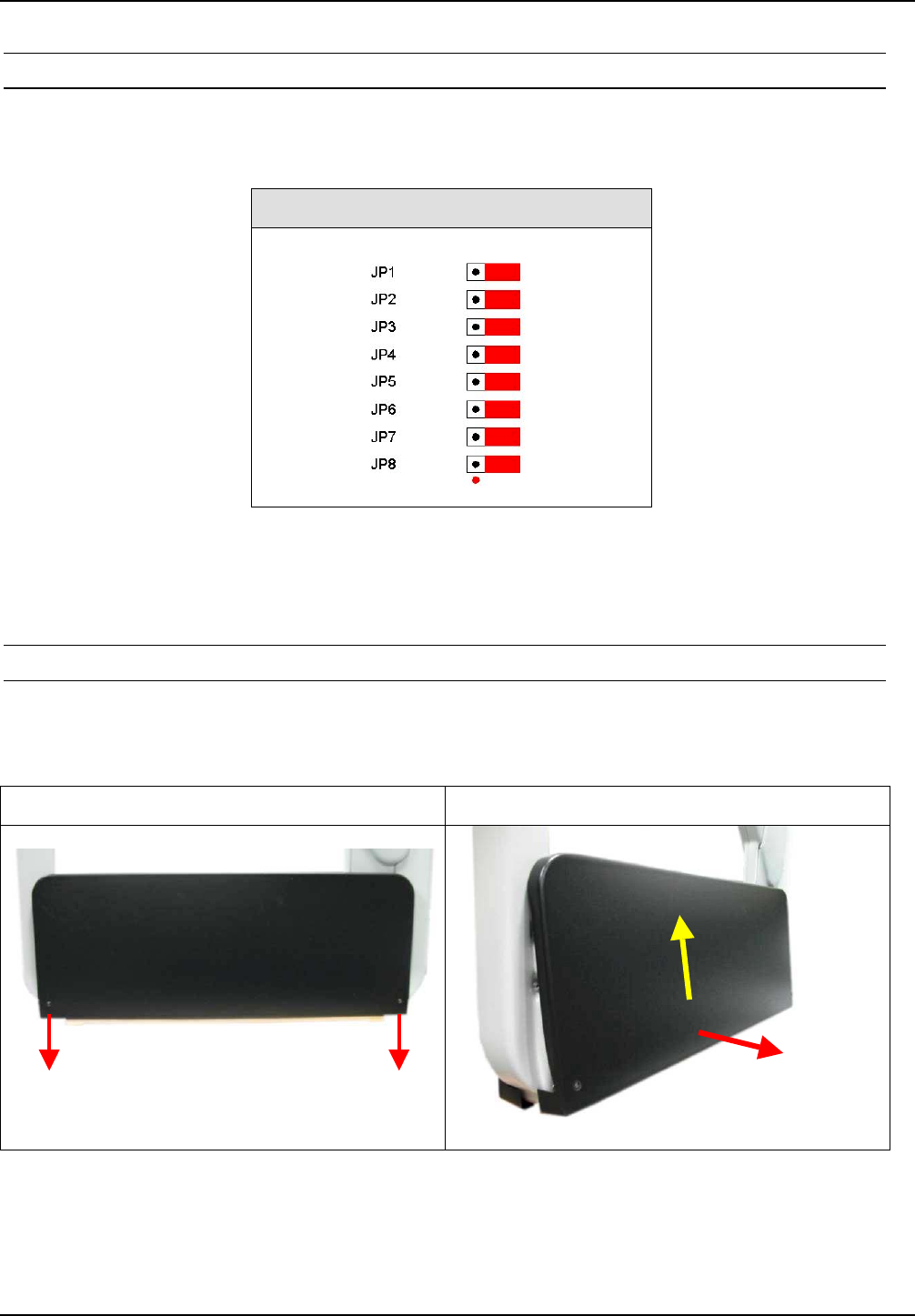
4.3.6 Jumper Configuration
Jumpers JP1 to JP8 must be set according to the following table.
Table 6: Configuration JP1-8
Jumper Position
In addition, close jumpers JP11 to JP18.
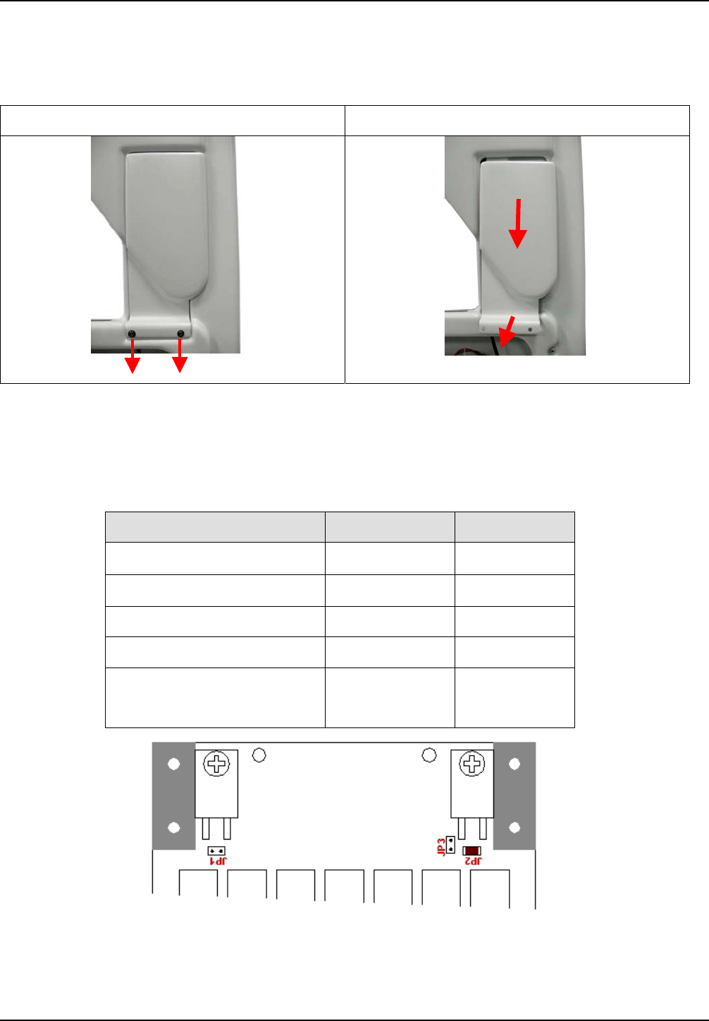
4.3.7 Setting the Antenna Tuner
To check the settings of the antenna tuner the antenna foot has to be opened. For that you must
remove the to fastening screws (hexagon socket width A/F2,5) of the antenna foot cover and
remove it upwards. Fig. 10
Step 1 Step 2
Fig. 15: Opening of the antenna foot
OBID i-scan®Installation ID ISC.ANT1300/680-A
FEIG ELECTRONIC GmbH Page 31 of 50 M71104-1e-ID-B.doc
Now you must remove the to fastening screws (hexagon socket width A/F2,5) of the antenna tuner
cover and remove it upwards. Fig. 11
Step 3 Step 4
Fig. 16 Removing the antenna tuner cover
ID ISC.ANT1300/680-A antennas must be set as follows (JP3 is factory set to closed and must be
opened):
Table 7: Jumper settings for Antenna Tuner
Function Jumper Position
1Ω Q resistor JP1 open
2Ω Q resistor JP2 closed
Antenna switch JP3 open
Capacitor C1 JP 11,12,13,14 open
Capacitor C2 JP 21,22,25,26
JP 23,24
open
closed
Verify these settings. More on setting the ID ISC.DAT antenna tuner can be found in the
corresponding installation manual (M40401-xde-ID-B).
OBID i-scan®Installation ID ISC.ANT1300/680-A
FEIG ELECTRONIC GmbH Page 32 of 50 M71104-1e-ID-B.doc
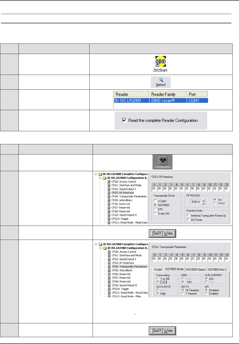
4.3.8 Reader Configuration with Multiplexer
To tune the antennas, open the ISOStart software and first read out the current configuration of the
Reader:
Step Action Note
1Start ISOStart Software
2Run „Detect“...
3...follow „New-File
Assistant“...
4...and read out the current
Reader Configuration
Then set the operating power, Transponder Parameters and ISO Host Mode:
Step Action Note
1Select “Configuration”
2
CFG3: RF-Interface
“RF-POWER” (here 8W)
Select “Transponders-Drivers”
(here ISO 15693)
3Set by clicking on “Write”
4
CFG4:
Transponder Parameters
Configure the parameters as
follows (ISO15693 Mode):
• „Datacoding“ – 1 of 4
• „MOD“ – 10%
• „SUB-CARRIER“ – ASK
• „DATA-RATE“ – High
• „NO-TS“ – 1 Timeslot
• „AFI“ – Disabled Note: National RF regulations may require different
settings. (see 4.7 Configuring the Reader in accordance
with national RF regulations)
5Set by clicking on “Write”
OBID i-scan®Installation ID ISC.ANT1300/680-A
FEIG ELECTRONIC GmbH Page 33 of 50 M71104-1e-ID-B.doc
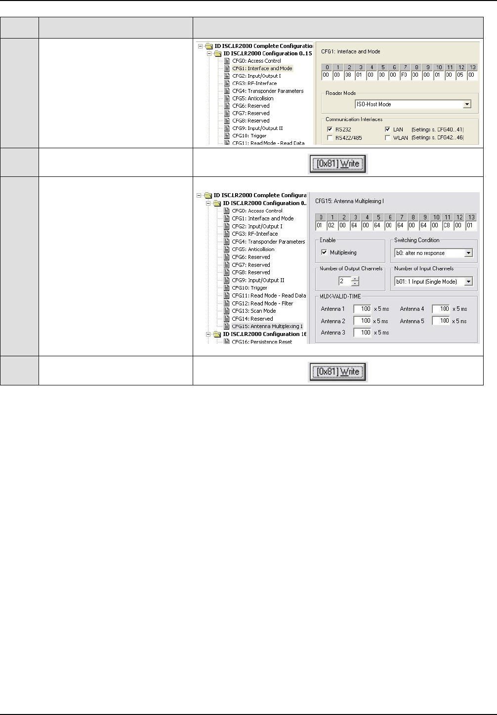
Step Action Note
6
CFG1: Interface and Mode
To tune, activate “ISO-Host
Mode”
7Set by clicking on “Write”
8
CFG15:
Antenna Multiplexing Ι
Activate „Multiplexing“
Configure the parameters as
follows:
• „Switching Condition“ –
after no response
• „Number of Input
Channels“ – 1 Input
(Single Mode)
• „MUX-Valid Time“ – 100 x
5 ms
• „Number of Output
Channels“ => 2
9Set by clicking on “Write”
OBID i-scan®Installation ID ISC.ANT1300/680-A
FEIG ELECTRONIC GmbH Page 34 of 50 M71104-1e-ID-B.doc
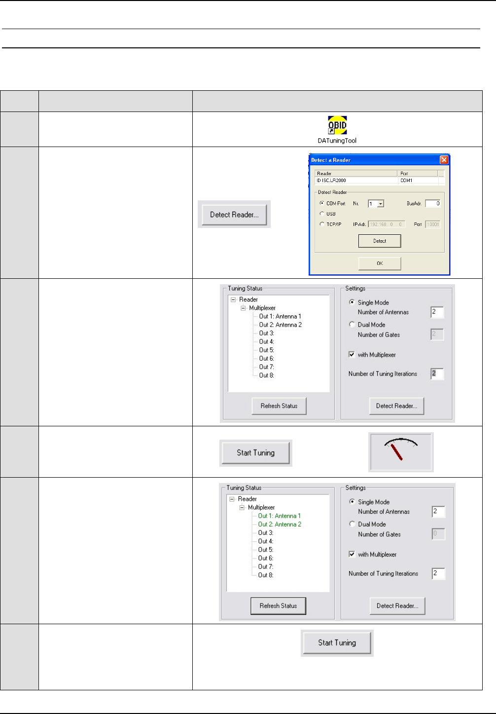
4.3.9 Tuning the Gate Antenna with Multiplexer
Before tuning the gate antenna, you must quit the ISOStart software. Then the gate can be tuned
as follows:
Step Action Note
1Start “DATuningTool” software
2
Select “Detect Reader...”.
In the „Detect Reader“ window
select the interface (COM-Port
1, BusAdr. 0) and then select
“Detect”.
3
Use „Settings“ to enter the
configuration:
Single Mode,
Number of Antennas 2
Click on “with Multiplexer“
Number of Tuning Iterations 3
4
Activate „Start Tuning“ and
wait until the tuning process is
finished. ... ...
5
The tuning status is displayed
after each tuning pass.
After successful tuning both
antennas are shown in green.
6
If this does not succeed on
the first try, start the process
over again by clicking on
„Start Tuning“
After successful tuning, close the DATuningTool again.
OBID i-scan®Installation ID ISC.ANT1300/680-A
FEIG ELECTRONIC GmbH Page 35 of 50 M71104-1e-ID-B.doc
4.4 Testing the Gate Antenna
After tuning the gate antenna, you can check for proper function using the Reader, the ISOStart
service software and a Smart Tag. Here the Noise Level and performance of the gate are tested.
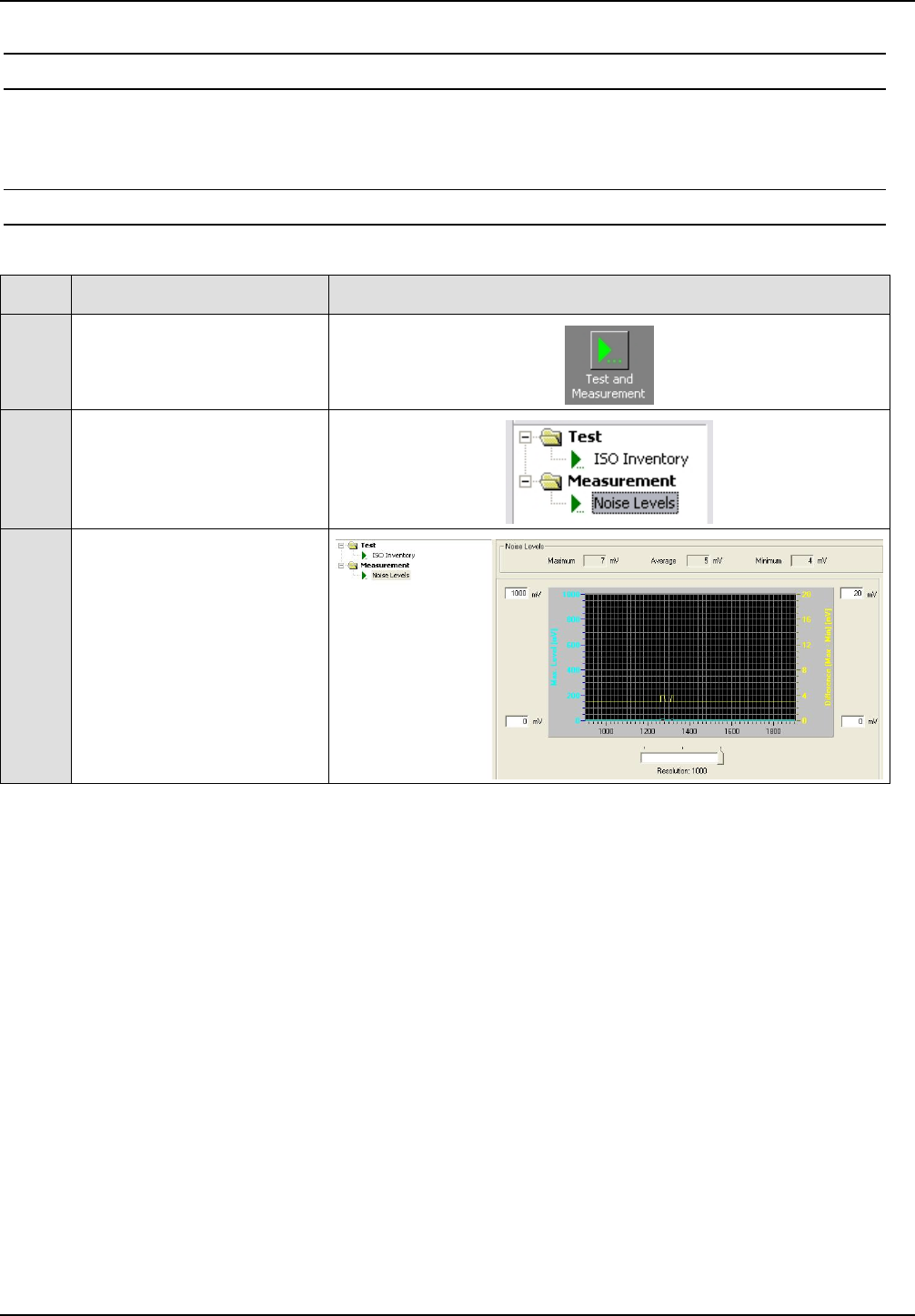
4.4.1 Checking the Noise Level
Step Action Note
1
Activate “Test and
Measurement”
2
Select „Noise Level“ and
start by clicking on „Start“
3
Normal Noise Level values:
Average:
< 50mV
Difference (Max-Min):
< 30mV
If the values are not met, check the following:
• Are all cables pulled tight and do they make good contact?
• Were the ring cores installed in the antenna cable?
• Were the cables routed as specified?
• Are other RFID systems installed nearby?
• Are there large metal parts near the antenna (distance < 1.0 m)?
• Are there devices nearby which may emit noise interference (larger machines or wireless
devices)?
• Are there interference from the mains?
To determine which devices may be disturbing the gate, briefly disconnect them from the mains.
OBID i-scan®Installation ID ISC.ANT1300/680-A
FEIG ELECTRONIC GmbH Page 36 of 50 M71104-1e-ID-B.doc
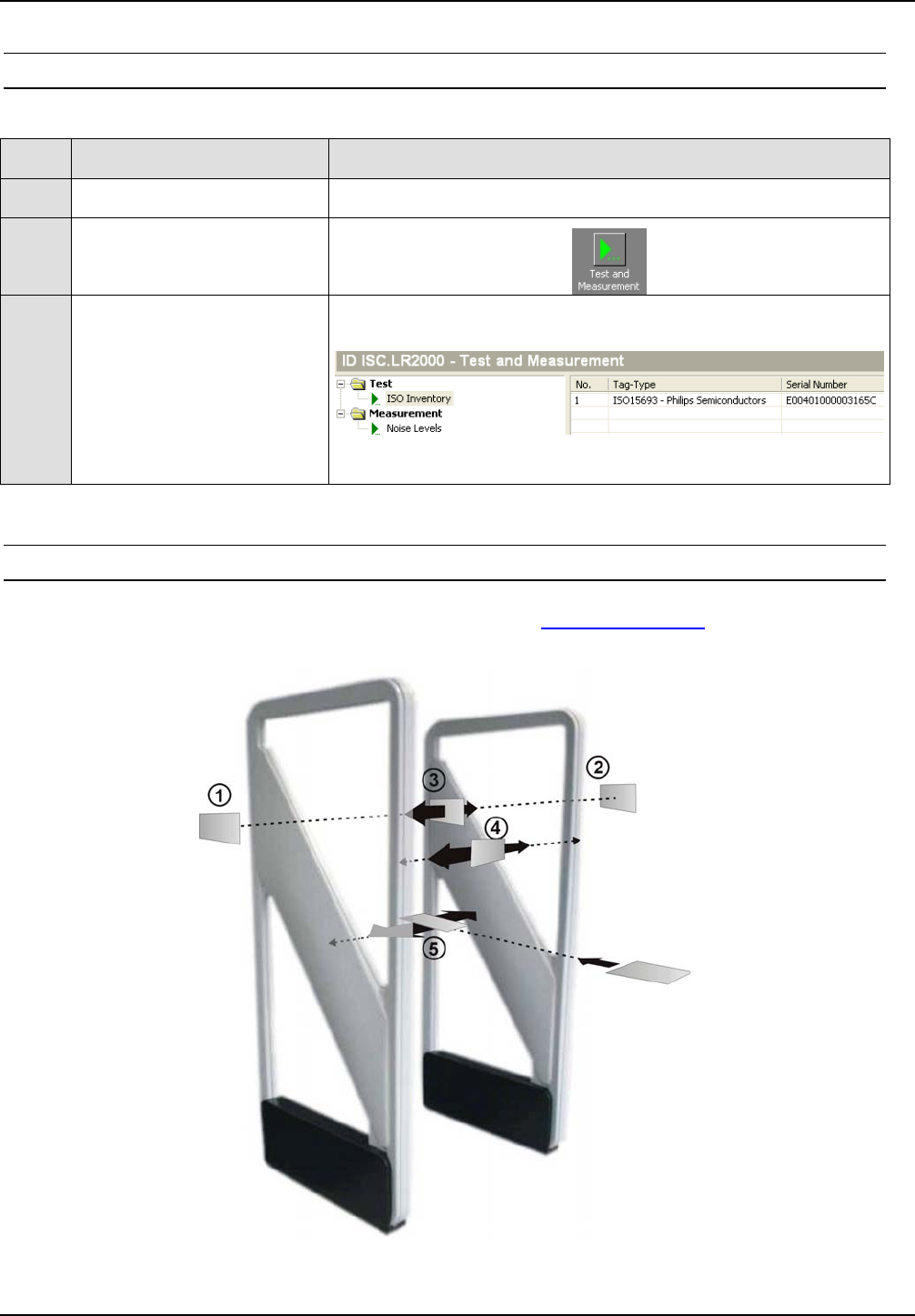
4.4.2 Reading a Serial Number
Step Action Note
1Attach a tag to an antenna Use adhesive tape, for example
2Select „Test and
Measurement“
3
Select „ISO Inventory“
function and activate by
clicking on „Start“.
The serial number and tag
type will be shown in the
display.
4.4.3 Testing the performance
In this test the capture area of the gate antenna described in 4.1 Project Notes is checked. For
other tags or other configurations the indicated ranges and read areas may differ accordingly.
Fig. 17: Performance Test of the gate antenna

OBID i-scan®Installation ID ISC.ANT1300/680-A
FEIG ELECTRONIC GmbH Page 37 of 50 M71104-1e-ID-B.doc
The test begins by checking the read range outside the gate (see Fig. points c and d), assuming
the configuration and locality permit it. Start the ISO Inventory command in the ISOStart program
as described in 4.4.2 Reading a Serial Number. If the tag is oriented parallel to the antenna
towards the outside, a read range of 65 to 75 cm should be achieved.
The three tag orientations are checked inside the gate. This corresponds to the lines and
orientations efg. Now slowly move the tag in the vertical and parallel direction with respect to
the antenna along the line e from one side to the other. The tag should always be read.
Then repeat this along the line f in the vertical tag direction transverse to the antenna and on the
line g in the horizontal tag orientation. Here again the tag should always be read.
The tag should be read within the gate when moving horizontally through the gate in all 3
read orientations.
If one or more „holes“ are detected, check the noise values on the Reader (see 4.4.1 Checking the
Noise Level) .
The following may result in faulty readings:
• Antenna improperly installed (orientation, antenna distance, check cabling)
• Metal near the antennas is detuning or interfering with them.
• The antennas are not properly tuned.
• Noise level too high (Vmax – Vmin ≥ 30 mV)
• Tag too insensitive, detuned or defective
• Reader improperly configured (transmitting power, transponder type, modulation, transponder
parameters, etc.).
• A cable is defective or has a poor contact.
• Reader, Power Splitter or antenna defective.
OBID i-scan®Installation ID ISC.ANT1300/680-A
FEIG ELECTRONIC GmbH Page 38 of 50 M71104-1e-ID-B.doc
4.5 Connecting and Setting the Alarm Kit (optional)
The solution provided here presumes that all alarm indicators (buzzer) are wired in parallel and
switched through the relay X11 on the ID ISC.LR2000-A-M Reader. The pulse duration can be set
(CFG2 / REL1) between 100 ms and 6553.5 s by adjusting the Reader configuration. Relay X11
provides a changeover contact for low voltages.
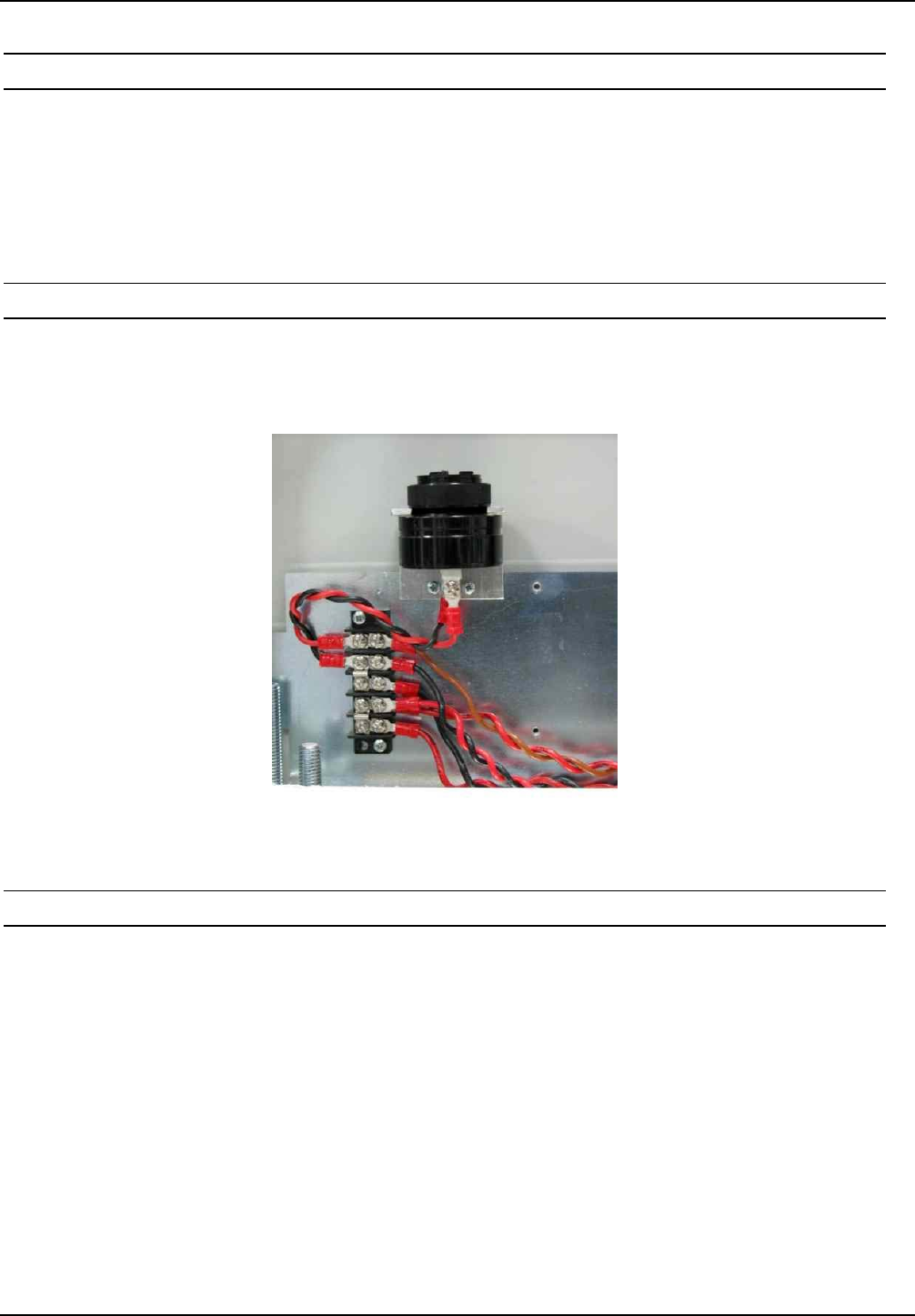
4.5.1 Installing the Alarm Indicators
The acoustic indicator, the buzzer, is installed in the antenna base as shown in Fig. 18. For the
installation you have to use the attached mounting bracket and the screws. The volume can be
adjusted with the attached manual volume controller which has to be mounted first.
Fig. 18: Installing the buzzer
4.5.2 Connecting the Indicators
The indicators are connected as shown in . The red wire (+) ahs to be connected with terminal 5
and the black wire (GND/-) has to be connected with terminal 4 of the terminal block.
Corresponding to that the wires have to be connected to the buzzer.
Notes:
The relay outputs are dimensioned for max. 24 V DC / 2 A.
The relay outputs are intended only for switching resistive loads. If an inductive load is used,
the relay contacts must be protected by an external protection circuit.
Reversing the polarity or overloading the outputs will destroy them.
See also Installation Manual ID ISC.LRM2000-A/B
OBID i-scan®Installation ID ISC.ANT1300/680-A
FEIG ELECTRONIC GmbH Page 39 of 50 M71104-1e-ID-B.doc
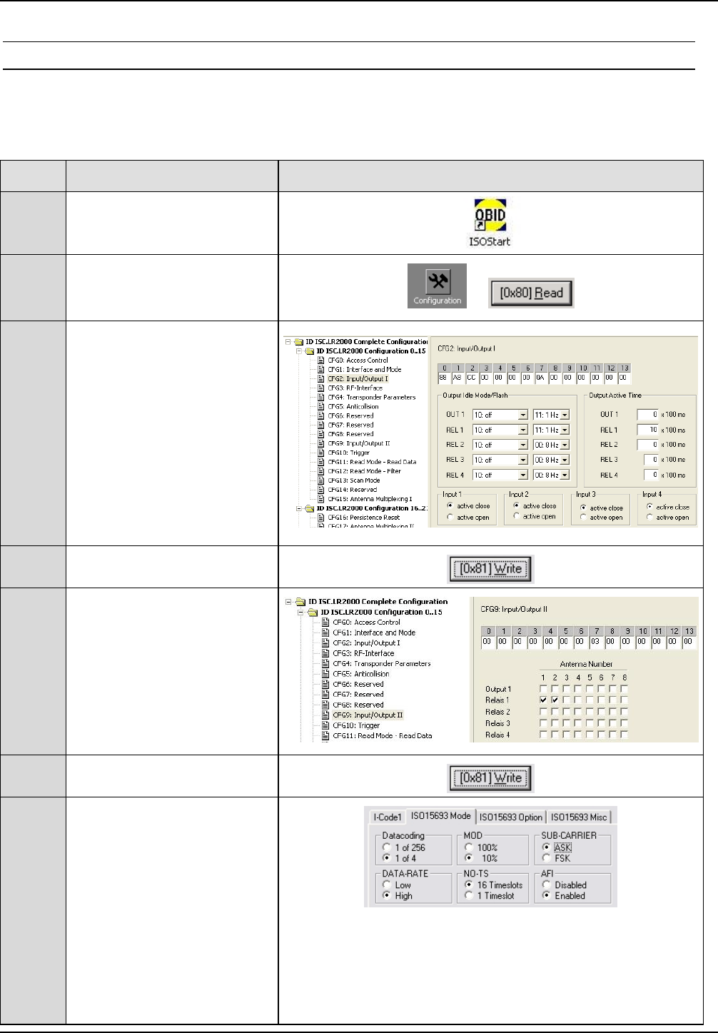
4.5.3 Reader Setting for Indicators
The ISOStart software can be used to set the Reader so that relay X11 opens or closes when a
Transponder is read.
Step Action Note
1Start ISOStart Software
2Select “Configuration” and
click on “Read” to read the .
3
CFG2: Input/Output Ι:
Output:
„REL1“ 10: off
Relay:
Use „REL-TIME“ to enter
desired alarm time for
relay (10 corresponds to 1
second
„REL-TIME“ 10 x 100ms
4Set by clicking on “Write”
5
CFG9: Input/Output ΙΙ
Assign Relay 1
to antenna 1+2
6Set by clicking on “Write”
7
CFG4:
Transponder Parameter
ISO 15693 Mode
„AFI“ Enabled

OBID i-scan®Installation ID ISC.ANT1300/680-A
FEIG ELECTRONIC GmbH Page 40 of 50 M71104-1e-ID-B.doc
7
ISO 15693 Mode
Enter desired value in
„AFI“ field.
8Set by clicking on “Write”
OBID i-scan®Installation ID ISC.ANT1300/680-A
FEIG ELECTRONIC GmbH Page 41 of 50 M71104-1e-ID-B.doc
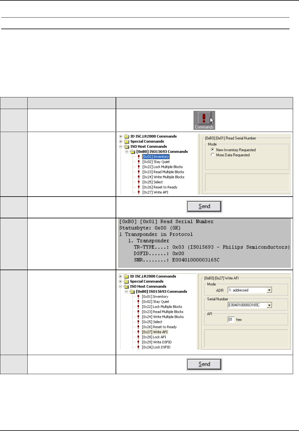
4.5.4 Programming a Transponder with the AFI Byte
If the transponders will remain on the object when leaving the storage location, they must first be
cancelled. This is generally done by writing to a particular area of the transponder.
The AFI byte (Application Family Identifier) is useful for this purpose, since it is contained in nearly
all transponder models in the 13.56 MHz family. To cancel, simply write a different code to the
transponder than for valid transponders which trigger an alarm.
Step Action: Note:
1Select „Commands“
2
Place the Transponder in the
antenna field (Antenna 1)
Select [0x01] Inventory
Select New Inventory
Requested
3Read UID by clicking on
„Send“
4
The serial number, DSFID
and Transponder type are
displayed in a window.
Write down the serial number
of the Transponder
5
Select „[0x27] Write AFI“
ADR:
1: addressed
Serial Number:
Select Transponder
AFI:
Desired AFI Number (not
equal to 00)
6Read UID by clicking on
„Send“

OBID i-scan®Installation ID ISC.ANT1300/680-A
FEIG ELECTRONIC GmbH Page 42 of 50 M71104-1e-ID-B.doc
7
To verify, read AFI byte by
selecting
[0x2B] Get System
Information
OBID i-scan®Installation ID ISC.ANT1300/680-A
FEIG ELECTRONIC GmbH Page 43 of 50 M71104-1e-ID-B.doc
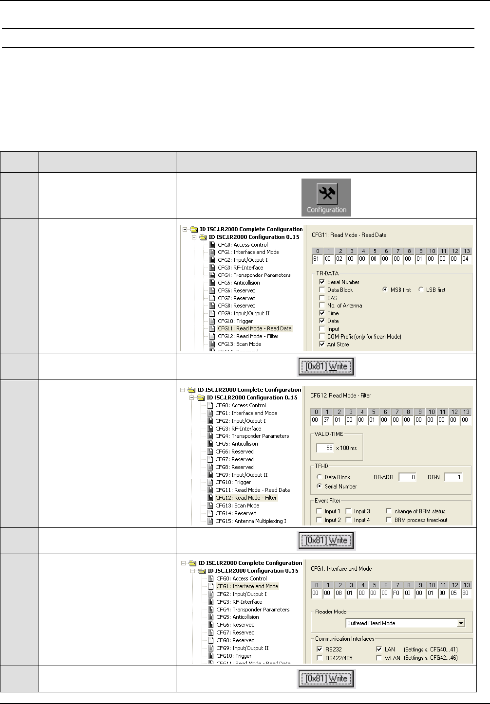
4.6 Activating Buffered Read Mode
„Buffered Read Mode“ is the normal operating mode of the Reader. Here the tags are read at
maximum speed and the information is stored in the Reader’s ring buffer. This data sets can be
read by the host.
To activate „Buffered Read Mode“ proceed as follows:
Step Action Note
1Select „Configuration“
2
CFG11:
Read Mode –Read Data
TR.DATA
Serial Number
Ant Store
3Set by clicking on “Write”
4
CFG12: Read Mode-Filter
VALID-TIME
e.g. 55 x 100 ms
5Set by clicking on “Write”
6
CFG1:
Interface and Mode
Select „Buffered Read
Mode“.
7Set by clicking on “Write”

OBID i-scan®Installation ID ISC.ANT1300/680-A
FEIG ELECTRONIC GmbH Page 44 of 50 M71104-1e-ID-B.doc
4.7 Configuring the Reader in accordance with national RF regulations
Configuration of the RFID Readers and the maximum transmitting power of the antennas are
affected mainly by the country-specific RF regulations. For the entire EU the limits are set forth in
the R&TTE Directive and EN 300 330. In North America this is regulated by FCC Part 15 (USA)
and by the RSS-210 (Canada).
The ID ISC.ANT1300/680 antenna with the ID ISC.LR2000 Reader, when used as intended,
complies with the basic requirements of Article 3 and the other relevant clauses of the R&TTE
Directive 1999/5/EG of March 99. This means that operation in the 29 EU countries and the EFTA
countries (EU countries plus Switzerland, Norway and Iceland) is possible with a maximum field
strength of 42 dBµA/m at 10 m distance.
RF approval (at a maximum field strength of 42 dBµA/m at 10 m) for the ID ISC.ANT1300/680
antenna with ID ISC.LRM2000 Reader has been granted in accordance with FCC Part 15 for the
USA and the RSS-210 for Canada
RF approval in accordance with EN 300 330 is still possible in all 46 CEPT countries.
The CEPT countries are:
Albania (ALB), Andorra (AND), Austria (AUT), Azerbaijan (AZE), Belarus (BLR), Belgium (BEL),
Bulgaria (BUL), Bosnia and Herzegovina (BIH), Croatia (HRV), Cyprus (CYP), Czech Republic
(CZE), Denmark (DNK), Estonia (EST), Finland (FIN), France (F), Germany (D), Greece (GRC),
Hungary (HNG), Iceland (ISL), Ireland (IRL), Italy (I), Latvia (LVA), Liechtenstein (LIE), Lithuania
(LTU), Luxembourg (LUX), Malta (MLT), Former Yugoslav Republic of Macedonia (MKD), Moldova
(MDA), Monaco (MCO), Netherlands (HOL), Norway (NOR), Poland (POL), Portugal (POR),
Romania (ROU), Russian Federation (RUS), San Marino (SMR), Slovak Republic (SVK), Slovenia
(SVN), Spain (E), Sweden (S), Switzerland (SUI), Turkey (TUR), Ukraine (UKR), United Kingdom
(G), Vatican City (CVA) and Yugoslavia.
The following restrictions are in effect (as of: July 2006):
1. Outside the EFTA countries RF approval must in all cases be applied for. The existing
measuring protocols in accordance with EN 300 330 are generally sufficient.
2. Operation in Croatia (HRV) (maximum field strength 42 dBµA/m) is only possible with an
individual license!
When placing the antennas in service, the systems integrator must ensure that the prescribed
mounting instructions are followed, the necessary Reader settings are made and permissible limits
according to the national regulations are not exceeded.

OBID i-scan®Installation ID ISC.ANT1300/680-A
FEIG ELECTRONIC GmbH Page 45 of 50 M71104-1e-ID-B.doc
The Reader needs to be configured as follows depending on the installation location:
Parameter USA / Canada / Europe
(42dBuA/m)
General
RF-Power – CFG 3 maximum 8 W
Downlink RF Modulation – CFG
20 / RF-Modulation
15%
ISO15693
Downlink RF Modulation – CFG
4 / ISO-MODE / MOD
10%
Downlink RF Data coding –
CFG 4 / ISO-MODE / FAST
Fast (1/4) or Normal (1/256)
Timeslots - CFG 4 / ISO-MODE
/ NO-TS
1 or 16 Timeslots
Inverntory Command Option –
CFG 4 / ISO-CMD-OPTION /
BREAK
Complete Timeslot length at
„NO TAG“

OBID i-scan®Installation ID ISC.ANT1300/680-A
FEIG ELECTRONIC GmbH Page 46 of 50 M71104-1e-ID-B.doc
5 Technical Data
5.1 Antenna ID ISC.ANT1300/680- Type A
Mechanical Data
• Housing UV stabilized ABS
• Dimensions ( W x H x D ) 720 x 1680 x 86 mm ± 5 mm
• Weight
– ID ISC.ANT1300/680-A Approx. 15 kg with/ 20 kg without packing
• Enclosure rating IP 54
• Color Antenna frame: light grey RAL 7035
Antenna foot: signal black RAL 9004
• Mounting
– No. of attaching points
– Recommended anchors
– Recommended minimum load
capacity of the floor fastener
2
∅ 10 mm
5000 N / anchor
• Maximum horizontal load on the top
edge of the antenna
250 N*
Electrical Data****
• Supply Voltage 24 V ± 15 %
Noise Ripple : max. 150 mV
• Power Consumption max. 32 VA
• Operating Frequency 13,56 MHz
• Transmit Power 2W – 12 W
(250 mW Step - Software)
• Modulation 10% - 30% and 100%
(Software configurable)
• Maximum transmitting power per
antenna
8 W

OBID i-scan®Installation ID ISC.ANT1300/680-A
FEIG ELECTRONIC GmbH Page 47 of 50 M71104-1e-ID-B.doc
• Permissible overall transmitting
power per antenna gate
– EU-territory (per EN 300 330) and
other CEPT nations
– USA (per. FCC Part 15)
8.0 W
8.0 W
• Outputs
– 1 Optocoupler
– 1 Differential Output
– 1 Relay ( 1 x Changeover)
24 V / 30 mA
Reader Synchronisation
24 V / 2 A for Alarm Kit
• Inputs
– 1 Optocoupler
– 1 Differential Input
Max. 24 V
/
20 mA
Reader Synchronisation
• Interfaces RS232
RS484 / RS422
Ethernet (TCP/IP)
Compact Flash II
(WLAN)
• Protocol Modes FEIG ISO HOST
BRM (Data Filtering and Data Buffering)
Scan Mode (RS 232/485/422)
Notification Mode (TCP/IP)
• Supported Transponders ISO 15693, ISO 18000-3-A, (EM HF ISO
Chips, Fujitsu HF ISO Chips, KSW Sensor
Chips, Infineon my-d, NXP I-Code , STM ISO
Chips, TI Tag-it)
NXP I-code 1, I-Code UID, I-Code EPC
• Ranges / pass-through width in gate
with power splitter
– One tag orientation
– All tag orientations
approx. 105 cm**
approx. 90 cm***
• Ranges / pass-through width in gate
with multiplexer
– One tag orientation
– All tag orientations
approx. 120 cm**
approx. 95 cm***
• Antenna connection 1 x SMA plug (50 Ω)
• Antenna connector cable RG58, 50 Ω, approx. 2 m long

OBID i-scan®Installation ID ISC.ANT1300/680-A
FEIG ELECTRONIC GmbH Page 48 of 50 M71104-1e-ID-B.doc
Ambient Conditions
• Temperature range
– Operating
– Storage
–25°C to +50°C
–25°C to +70°C
Applicable Standards
• RF approval
– Europe
– USA
EN 300 330
FCC Part 15
• EMC EN 301 489
• Safety
– Low Voltage Directive
– Human Exposure
UL 60950-1 (in preparation)
EN 50364
* Persistent deformation after load release approx. 1 cm.
** Qty. 2 ID ISC.ANT1300/680-A antennas, antenna spacing (antenna center), same flow direction,
Tag 46 mm x 75 mm ISO15693, sensitivity / minimum field strength Hmin=80 mA/m rms,
transmitting power 8 W, tag orientation parallel to antenna for horizontal movement through the
antenna. The detection performance also depending of the strength of the Transponder answer
signal !
*** Tag 46 mm x 75 mm ISO 15693, sensitivity / minimum field strength Hmin=80 mA/m rms,
transmitting power 8 W, aligned in all 3 dimensions for horizontal movement through the antenna.
The detection performance also depending of the strength of the Transponder answer signal !

OBID i-scan®Installation ID ISC.ANT1300/680-A
FEIG ELECTRONIC GmbH Page 49 of 50 M71104-1e-ID-B.doc
5.2 Approval
As per Section 4.7 Configuring the Reader in accordance with national RF regulations!
5.2.1 Europe (CE)
This RF equipment is in compliance with the essential requirements and other relevant provisions
of Directive 1999/5/EC dated March 99.
Equipment Classification according to ETSI EN 300 330 and ETSI EN 301 489: Class 2
The technical data of the ID ISC.LRM2000 Reader built into the ID ISC.ANT1300/680-A an-
tenna can be found in the Installation Manual which is included with the device.

OBID i-scan®Installation ID ISC.ANT1300/680-A
FEIG ELECTRONIC GmbH Page 50 of 50 M71104-1e-ID-B.doc
5.2.2 USA (FCC) and Canada (IC)
Product name: ID ISC.ANT1300/680
Antenna name: ID ISC.ANT1300/680 Type A
Reader name: ID ISC.LRM2000-A
FCC ID:
IC:
PJMANT1300680
6633A-ANT130068
Notice for USA and
Canada
This device complies with Part 15 of the FCC Rules and with
RSS-210 of Industry Canada.
Operation is subject to the following two conditions.
(1) this device may not cause harmful interference, and
(2) this device must accept any interference received,
including interference that may cause undesired operation.
Unauthorized modifications may void the authority granted under
Federal communications Commission Rules permitting the operation
of this device.
This equipment has been tested and found to comply with the limits for
a Class A digital device, pursuant to Part 15 of the FCC Rules. These
limits are designed to provide reasonable protection against harmful
interference when the equipment is operated in a commercial
environment. This equipment generates, uses, and can radiate radio
frequency energy and, if not installed and used in accordance with the
instruction manual, may cause harmful interference to radio
communications. Operation of this equipment in a residential area is
likely to cause harmful interference in which case the user will be
required to correct the interference at his own expense.
Cet appareil numérique de la classe A est conforme à la norme NMB-
003 du Canada.
Further information and technical data of the ID ISC.LRM2000 Reader built into the
ID ISC.ANT1300/680-A antenna can be found in the Installation Manual which is included
with the device.
OBID i-scan®Installation ID ISC.ANT1300/680-A
FEIG ELECTRONIC GmbH Page 51 of 50 M71104-1e-ID-B.doc
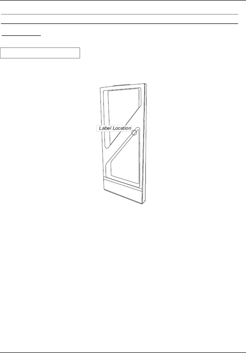
5.2.3 USA (UL)
In preparation !
The following picture indicates the label position: