Feig Electronic CPR03 Inductive Tag Reader User Manual ID CPR03 Manual
Feig Electronic GmbH Inductive Tag Reader ID CPR03 Manual
Users Manual
INSTALLATION
Page 1 of 11
OBI
D
®
classic-
p
ro
ID CPR.03-VP/AB-A
Multitag Reader Data/Clock

OBID® classic-pro Installation ID CPR.03-VP/AB-A
FEIG ELECTRONIC GmbH Page 2 of 11
Note
© Copyright 2006 by
FEIG ELECTRONIC GmbH
Lange Strasse 4
D-35781 Weilburg-Waldhausen
Tel.: +49 6471 3109-0
http://www.feig.de
With the edition of this document, all previous editions become void. Indications made in this manual may be
changed without previous notice.
Copying of this document, and giving it to others and the use or communication of the contents thereof are
forbidden without express authority. Offenders are liable to the payment of damages. All rights are reserved
in the event of the grant of a patent or the registration of a utility model or design.
Composition of the information in this manual has been done to the best of our knowledge. FEIG
ELECTRONIC GmbH does not guarantee the correctness and completeness of the details given in this
manual and may not be held liable for damages ensuing from incorrect or incomplete information. Since,
despite all our efforts, errors may not be completely avoided, we are always grateful for your useful tips.
The installation instructions given in this manual are based on advantageous boundary conditions. FEIG
ELECTRONIC GmbH does not give any guarantee promise for perfect function in cross environments.
FEIG ELECTRONIC GmbH assumes no responsibility for the use of any information contained in this
manual and makes no representation that they free of patent infringement. FEIG ELECTRONIC GmbH does
not convey any license under its patent rights nor the rights of others.
OBID® and OBID i-scan® is a registered trademark of FEIG ELECTRONIC GmbH.
my-d® is a registered trademark of Technologies AG
I-CODE® and mifare® is a registered trademark of Philips Electronics N.V.
Tag-itTM is a registered trademark of Texas Instruments Incorporated

OBID® classic-pro Installation ID CPR.03-VP/AB-A
FEIG ELECTRONIC GmbH Page 3 of 11
Contents
1 Safety Instructions / Warning - Read before start-up ! 4
2 Introduction 4
3 Technical Specifications 5
Dimensions ..................................................................................................................................6
3.2 Approval.........................................................................................................................6
4 Installation 7
4.1 Mounting ........................................................................................................................7
4.2 Connection.....................................................................................................................8
4.3 Configuration.................................................................................................................9
4.3.1 Default Configuration....................................................................................................9
4.3.2 Reloading the configuration.........................................................................................9
5 Normal Operating Mode 10
5.1 Digital Inputs................................................................................................................10
5.2 Data-/Clock Interface...................................................................................................11
5.3 Asynchronous Interface: RS232-TTL ........................................................................11
6 System Delivery Contents 11

OBID® classic-pro Installation ID CPR.03-VP/AB-A
FEIG ELECTRONIC GmbH Page 4 of 11
1 Safety Instructions / Warning - Read before start-up !
• The device may only be used for the intended purpose designed by for the
manufacturer.
• The operation manual should be conveniently kept available at all times for each user.
• Unauthorized changes and the use of spare parts and additional devices which have not
been sold or recommended by the manufacturer may cause fire, electric shocks or
injuries. Such unauthorized measures shall exclude any liability by the manufacturer.
• The liability-prescriptions of the manufacturer in the issue valid at the time of purchase
are valid for the device. The manufacturer shall not be held legally responsible for
inaccuracies, errors, or omissions in the manual or automatically set parameters for a
device or for an incorrect application of a device.
• Repairs may only be executed by the manufacturer.
• Installation, operation, and maintenance procedures should only be carried out by
qualified personnel.
• Use of the device and its installation must be in accordance with national legal
requirements and local electrical codes .
• When working on devices the valid safety regulations must be observed.
• Special advice for carriers of cardiac pacemakers:
Although this device doesn't exceed the valid limits for electromagnetic fields you
should keep a minimum distance of 25 cm between the device and your cardiac pace-
maker and not stay in an immediate proximity of the device respective the antenna for
some time.
2 Introduction
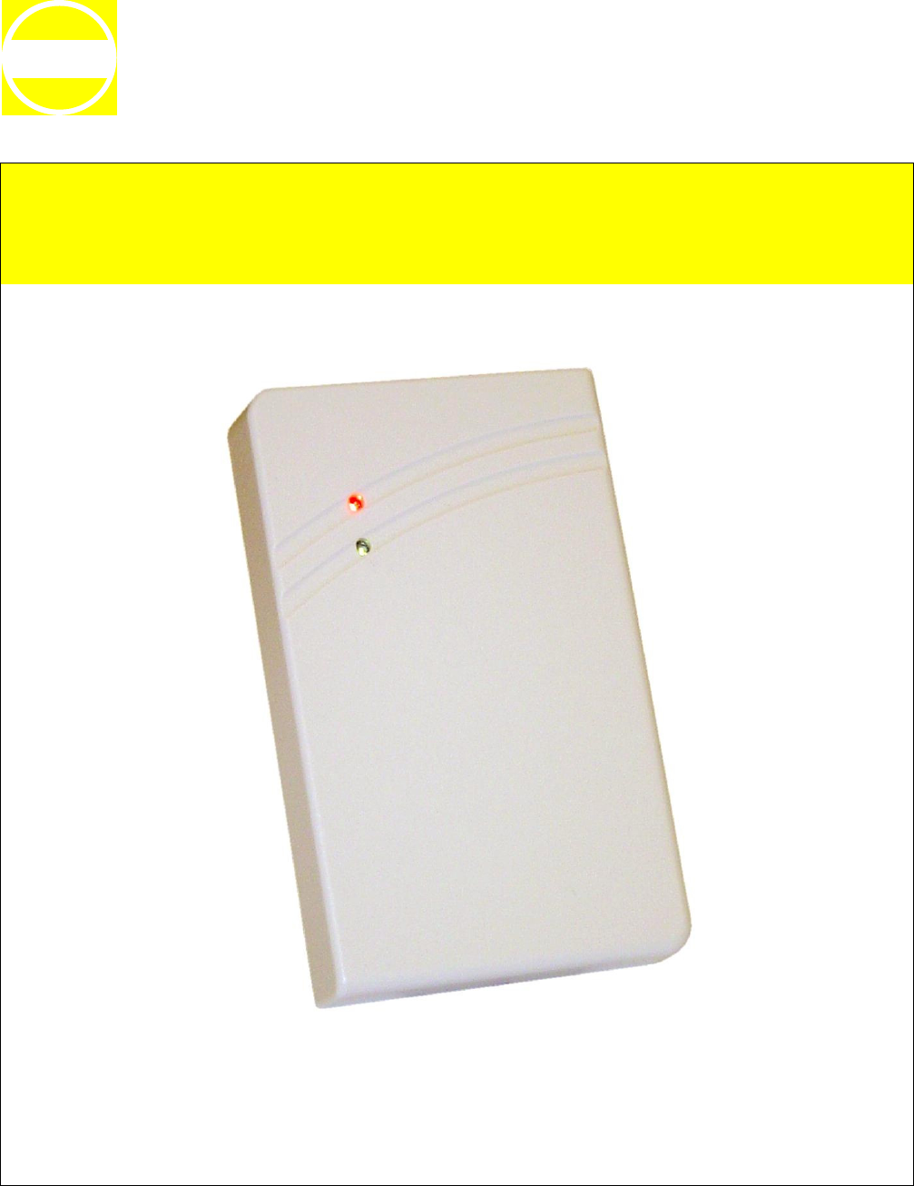
The Multitag-Reader ID CPR.03-VP/AB-A is designed for access control and time-recording sys-
tems. Via the configurable data-/clock interface it can connected easily with usual access control
and time-recording controllers.
The ID CPR.03-VP/AB-A could read the serial-no. (UID) of the most common 13,56 MHz Trans-
ponder according ISO 14443 type A, ISO 14443 type B and ISO 15693.
The ID CPR.03-VP/AB-A is designed to be wall-mounted onto flat and non-conductive walls with or
without a flush-mounting box.
The data-/clock interface could configured like Wiegand- or magnetic stripe format (ISO7811-2,
5 Bit).
The configuration could changed while installation with a ConfigCard transponder. This ConfigCard
could prepared comfortable before Installation with a separate tool.

OBID® classic-pro Installation ID CPR.03-VP/AB-A
FEIG ELECTRONIC GmbH Page 5 of 11
3 Technical Specifications
Housing Plastic ABS (sealed-in electronics)
Color gray - beige
Weight approx. 170 g
Protection class IP 65
Power Supply 9 - 15 V DC
Power Consumption max. 2,6 W
Temperature range Operating
Storage
-25 °C to +60 °C
-40 °C to +85 °C
Relative humidity 95% (not condensing)
Antenna internal
Operating Frequency 13,56 MHz
Transmitting power 200 mW ± 2 dB
Supported Transponder
(read UID)
• ISO14443A:
e.g. mifare® Standard, mifare® UltraLight, mifare® DESfire,
Smart MX, my-d® proximity, SLE44R35S, SLE55R.., etc.
• ISO14443B:
e.g. SLE66CL, ST19XR34, etc.
• ISO15693:
e. g. my-d vicinity, I•Code SLI, TagIT HFI, STM LRI512, etc.
Connecting cable 50 cm, LiYY 12 * 0,23 mm2 / AWG24
Signal Transmitter 1 x LED red
1 x LED green
1 x Beeper
Digital Inputs 1 x switches LED red
1 x switches LED green
1 x switches Beeper
1 x Hold Function
Interface 1. Data/Clock Emulation:
- Magnetic Stripe (ISO7811-2, 5 Bit)
- Wiegand
2. RS232-TTL (for Service only)
Flash In-circuit firmware update possible
Applicable Standards:
• RF approval
- Europe
- USA
• EMC
• Safety
- Low Voltage
- Human Exposure
EN 300 330
FCC 47 CFR Part 15
EN 301 489
EN 60950
EN 50364
OBID® classic-pro Installation ID CPR.03-VP/AB-A
FEIG ELECTRONIC GmbH Page 6 of 11
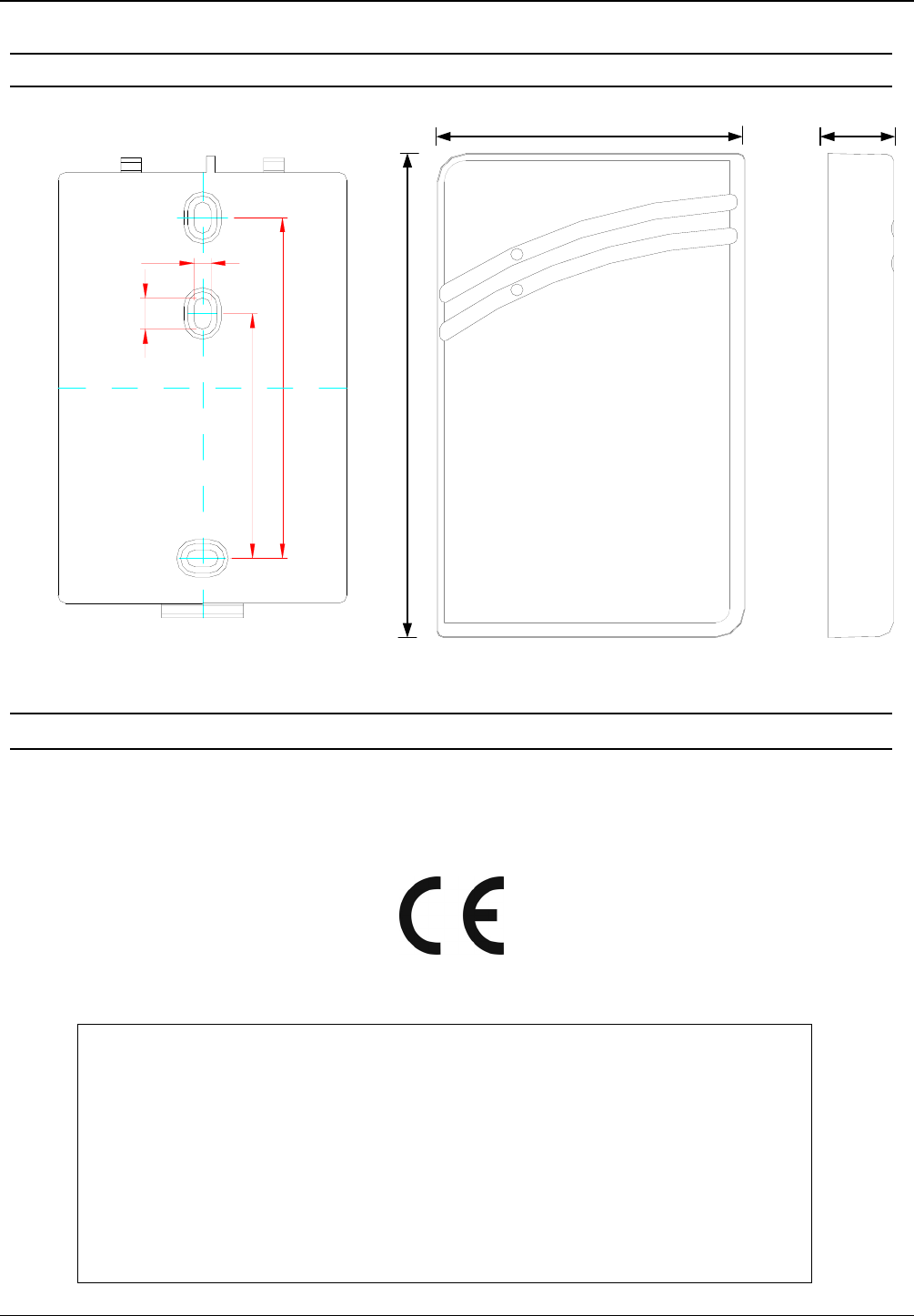
3.1 Dimensions
3.2 Approval
When properly used this radio equipment conforms to the essential requirements of Article 3 and
the other relevant provisions of the R&TTE Directive 1999/5/EC of March 99.
Equipment Classification according to ETSI EN 300 330 and ETSI EN 301 489: Class 2
FCC ID: PJMCPR03
This device complies with Part 15 of the FCC Rules. Operation is subject to the following
two conditions:
(1) this device may not cause harmful interference, and
(2) this device must accept any interference received, including interference that may
cause undesired operation.
Any changes or modifications not expressly approved by the party responsible for
compliance void the user's authority to operate the equipment.
75 17
83,5
60
7,7
4,2
120
OBID® classic-pro Installation ID CPR.03-VP/AB-A
FEIG ELECTRONIC GmbH Page 7 of 11
4 Installation
The ID CPR.03-VP/AB-A is designed to be wall-mounted with or without a 60 mm flush-mounting
box
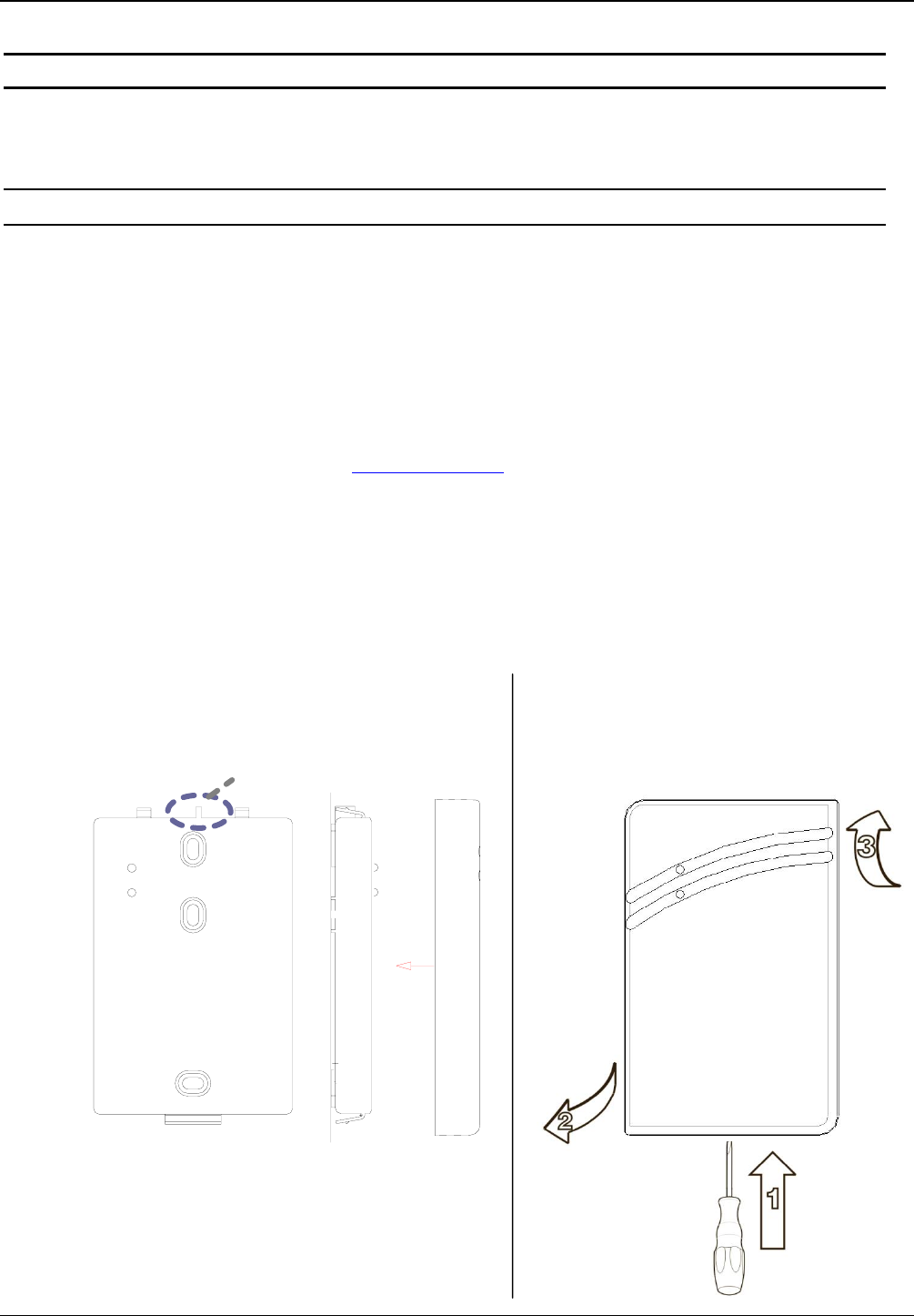
4.1 Mounting
• The reader should not be mounted directly onto conductive materials, such as metal surfaces,
metal frames (reinforcement) or metal-plated surfaces, as these surfaces will reduce the
reader's range. The clearance to such surfaces should be at least 30 mm.
• The distance between readers of the same design should not be less than 50 cm.
• Before final installation, the planned installation site should be checked for suitability.
• Only install the reader after successful commissioning. The power supply must be discon-
nected for configuration (see also : 4.3 Configuration).
• Use the screws provided (3.2 x 25 mm) for installation on 60 mm DIN flush-mounting boxes.
• For other installation methods use 3 mm countersunk-head screws to DIN 963 or with a coun-
tersunk head max. diameter of head 5.6 mm.
TOP
Assembling Disassembling
OBID® classic-pro Installation ID CPR.03-VP/AB-A
FEIG ELECTRONIC GmbH Page 8 of 11
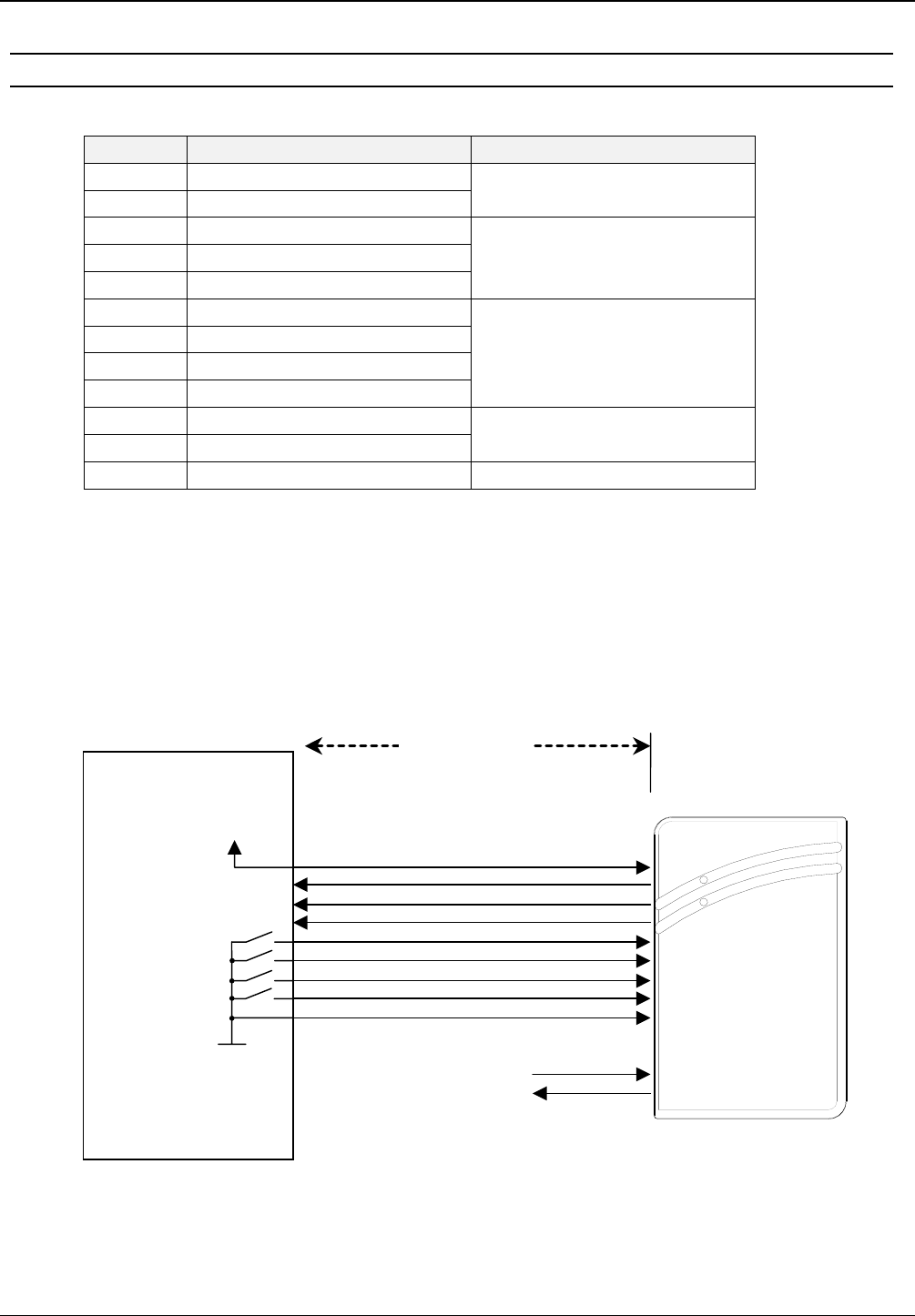
4.2 Connection
Colour Function Description
red Vcc (+9 to +15 V DC)
black GND* Power Supply
green Data / Data0
white Clock / Data1
violet CLS / Card Present
Clock/Data interface
(magnetic strip/ Wiegand)
grey LED green
brown LED rot
yellow Beeper
blue Hold
digital input**
pink RS232-TTL (Rx)
red / blue RS232-TTL (Tx) Service -Interface
grey / pink - N.C. -
*) If the power is not supplied via the controller the power supply GND must be connected
to the controller GND.
**) The digital inputs may only be wired to ground. Wiring to an external power supply may
destroy the input.
Controller
Vcc
Data / Data0
Clock / Data1
CLS
LED green
LED red
Beepe
r
Hold
GND
red
green
white
violet
grey
brown
yellow
blue
black
pink
red/blue
+9..15 V DC
max. 150 m

OBID® classic-pro Installation ID CPR.03-VP/AB-A
FEIG ELECTRONIC GmbH Page 9 of 11
4.3 Configuration
Configuration is carried out by means of a ConfigCard. An ISO 15693 transponder can be used as
ConfigCard (e.g. Infineon my-d, SFR55V10P, Philips I-CODE SLI, etc.)
The configuration data are stored in a specified read/write data block on the transponder. The
transponder is also provided with identifiers which enable recognition as the ConfigCard.
The creation and modification of a ConfigCard could be done the FEConfigCardTool which is available for
Windows operating systems.
4.3.1 Default Configuration
The factory configuration of the reader is as follows:
• Reads serial numbers (UID) of ISO 14443 Type A, ISO 14443 Type B and ISO 15693 trans-
ponders.
• Data output: Magstripe Track II, binary (80-bit) format.
4.3.2 Reloading the configuration
1. Switch on the power supply.
2. Hold the ConfigCard in the reading range during the configuration phase (8 seconds). During
this time the red and green LEDs flash alternately.
3. After the configuration is complete the reader automatically switches back to normal mode.
Signals:
The reader acknowledges a ConfigCard with the following signals:
1 x LED green + Beeper (1 s) ⇒ OK
ConfigCard has been processed, reader is operating with the new configuration
3 x LED rot + Beep ⇒ Fault
ConfigCard Identifier is not read correctly.
⇒ Repeat procedure.
⇒ Check the ConfigCard for correct programming.
Note:
ConfigCards with incorrect AFI are not recognized by the reader. No signaling is
possible

OBID® classic-pro Installation ID CPR.03-VP/AB-A
FEIG ELECTRONIC GmbH Page 10 of 11
5 Normal Operating Mode
Idle State (no Transponder detected):
In idle state the reader is searching permanent for a Transponder.
red LED = active
Transponder detected:
After a Transponder is detected by the ID CPR.03-VP/AB-A the data's are transmitted via
data-/clock interface once and the beeper sounds for a short time. At the same time the
red LED turns off for timeout time which is configured (default configuration 2 sec.).
To transmit the data's a second time the Transponder must leave the detection field of the
ID CPR.03-VP/AB-A for more then 1,5 seconds.
UID Length Error
If the Transponder UID is shorter than configured in ID CPR.03-VP/AB-A a length error is
signalized with 2 short beeps. In this case no data's are transmitted via data-/clock inter-
face.
5.1 Digital Inputs
LED red:
Activates the red LED, as long as the input is connected to GND.
LED green:
Activates the green LED and deactivates the red LED, as long as the input is connected to
GND.
Beeper:
Activates the beeper LED, as long as the input is connected to GND.
Hold:
Will not accept a transponder, as long as the input is connected to GND.

OBID® classic-pro Installation ID CPR.03-VP/AB-A
FEIG ELECTRONIC GmbH Page 11 of 11
5.2 Data-/Clock Interface
Depending on the reader configuration the hexadecimal coded UID (max. 10 byte) of the Trans-
ponder could be transmitted in different formats via data-/clock interface.
Details are described in ID CPR.03-VP/AB-A Manual (Document No: H60100-#e-ID-B)
5.3 Asynchronous Interface: RS232-TTL
The RS232-TTL Interface is designed only for firmware update. The firmware is stored in a flash
chip. The firmware is updated via the serial RS232 (TTL) reader port.
The red and green LED is active during the firmware update process.
The firmware update is described in ID CPR.03-VP/AB-A Manual (Document No: H60100-#e-ID-B)
6 System Delivery Contents
1 x housing base including sealed-in electronics
1 x housing cover
1 x accessory bag (2 screws 3,2x 25 mm)
1 x Mounting Instruction