Feig Electronic CPR5010 RFID Reader User Manual
Feig Electronic GmbH RFID Reader
UserManual.wiki
>
Feig Electronic
>
CPR5010 User Manual
User Manual
Navigation menu
Upload a User Manual
Namespaces
Wiki Guide
HTML
PDF
Info
Views
User Manual
Discussion / Help
Navigation


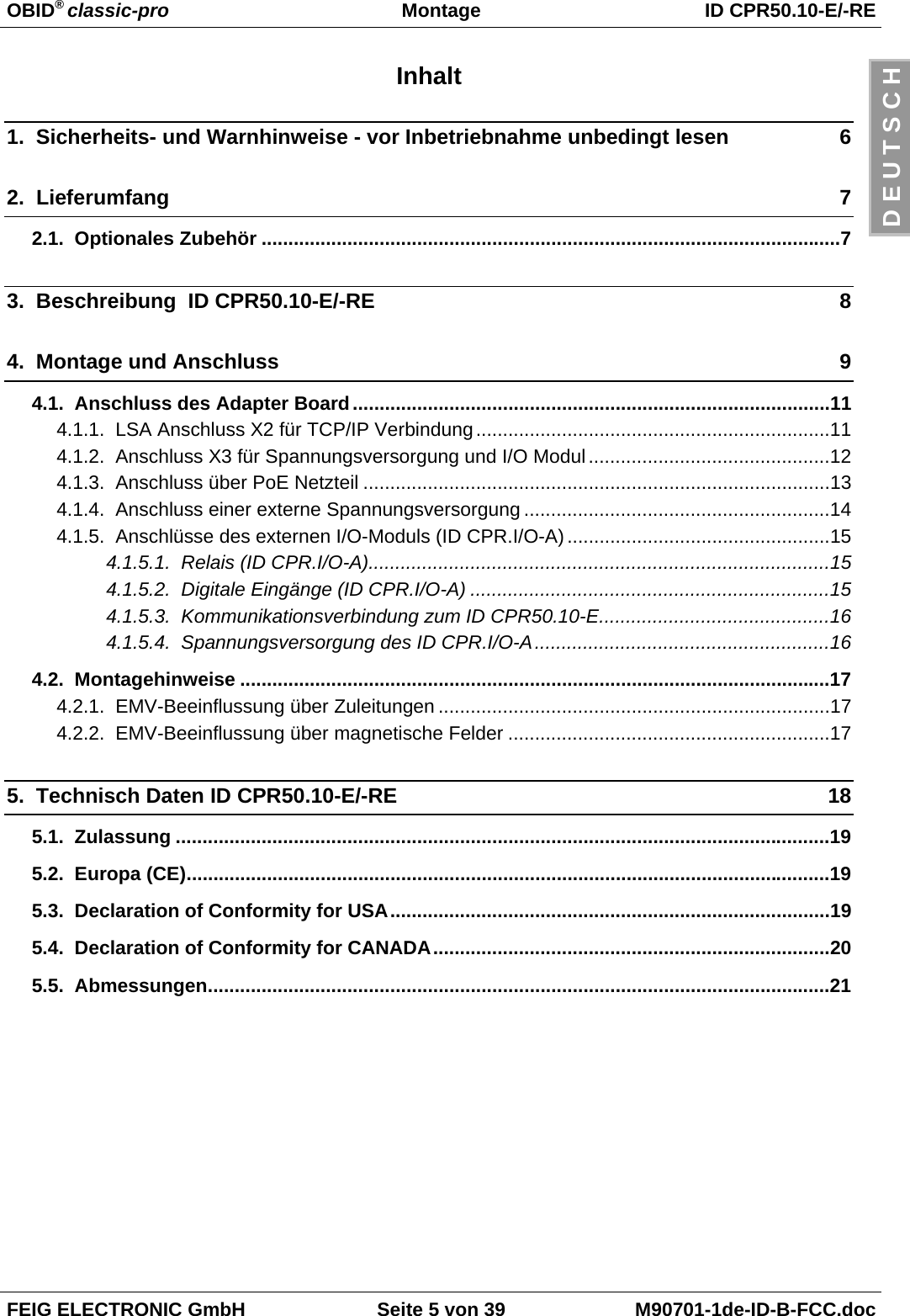
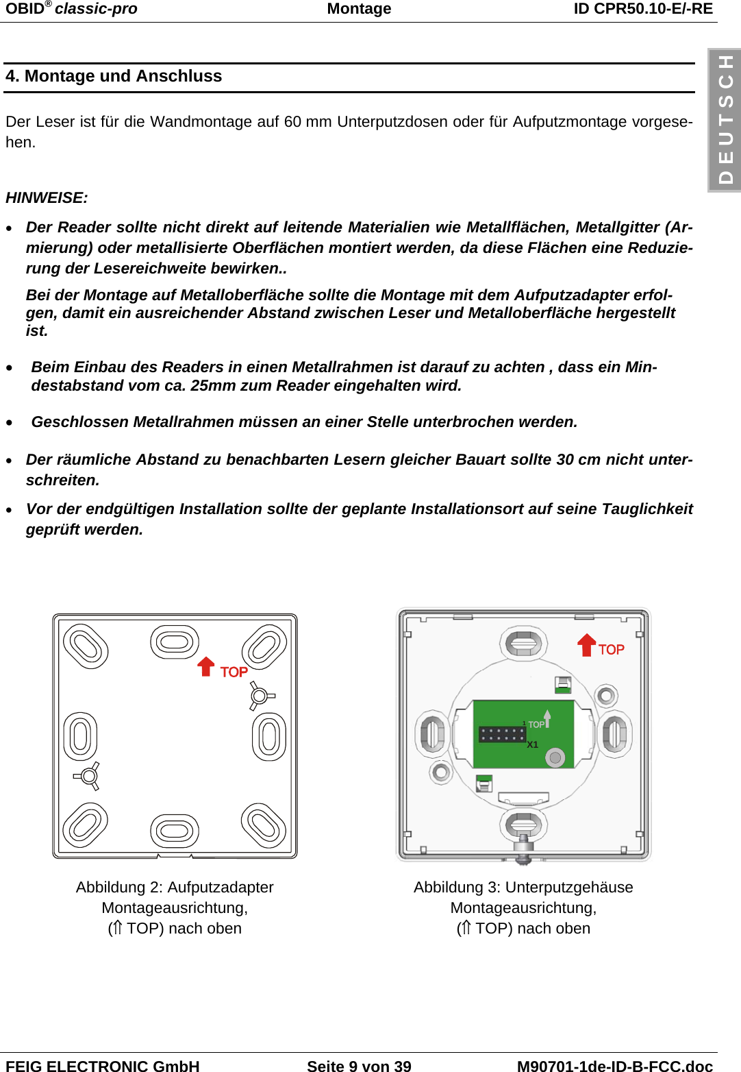
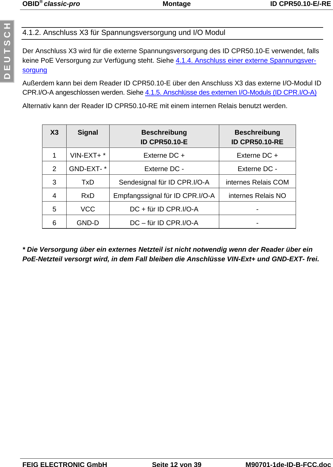
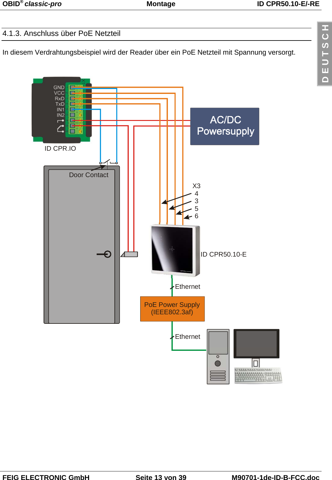
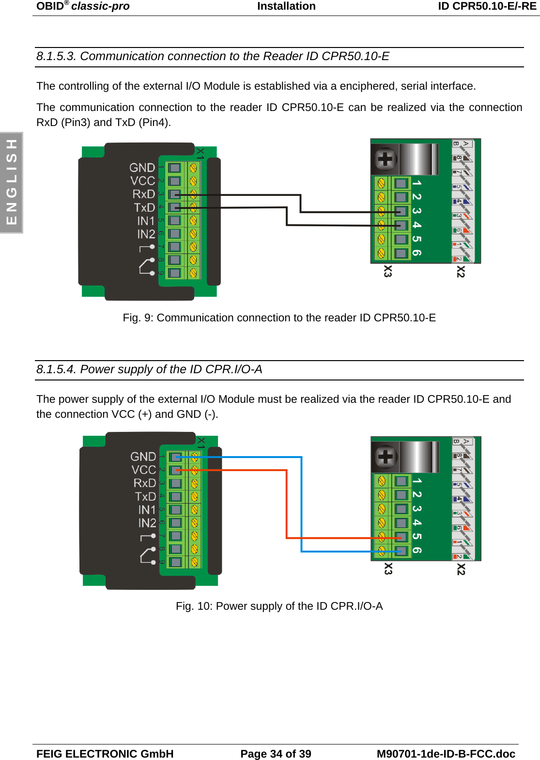
![OBID® classic-pro Montage ID CPR50.10-E/-REFEIG ELECTRONIC GmbH Seite 15 von 39 M90701-1de-ID-B-FCC.docD E U T S C H4.1.5. Anschlüsse des externen I/O-Moduls (ID CPR.I/O-A)Wenn ein Relais oder digitaler Eingang benötigt wird, kann das optionale externe Erweiterungs-modul ID CPR.I/O-A angeschlossen werden. GNDVCCRxDTxDIN1IN21 2 3 4 5 6 7 8 9X1Abbildung 8: ID CPR.I/O-AX1 Pin Kurzzeichen Beschreibung Verbunden mit Pin x on X3 CPR50.10-E1GND Ground 6 (GND-D)2VCC +5 VDC 5 (VCC)3RxD Receive Input 4 (OUT)4TxD Transmit Output 3 (IN)5 IN1 Digitaler Eingang 1 -6 IN2 Digitaler Eingang 2 -7Relais NO8Relais COM9Relais NC-4.1.5.1. Relais (ID CPR.I/O-A)Das ID CPR.I/O-A Module verfügt über ein Relais mit einem Wechselkontakt. Der Anschluss er-folgt über die Klemmen 7 [NO], 8 [COM] und 9 [NC].4.1.5.2. Digitale Eingänge (ID CPR.I/O-A)Die digitalen Eingänge [IN1] und [IN2]) dürfen nur gegen Ground, Klemme [GND] geschaltet wer-den.Eine Beschaltung mit Fremdspannung kann zur Zerstörung des Gerätes führen!](https://usermanual.wiki/Feig-Electronic/CPR5010/User-Guide-1187286-Page-15.png)
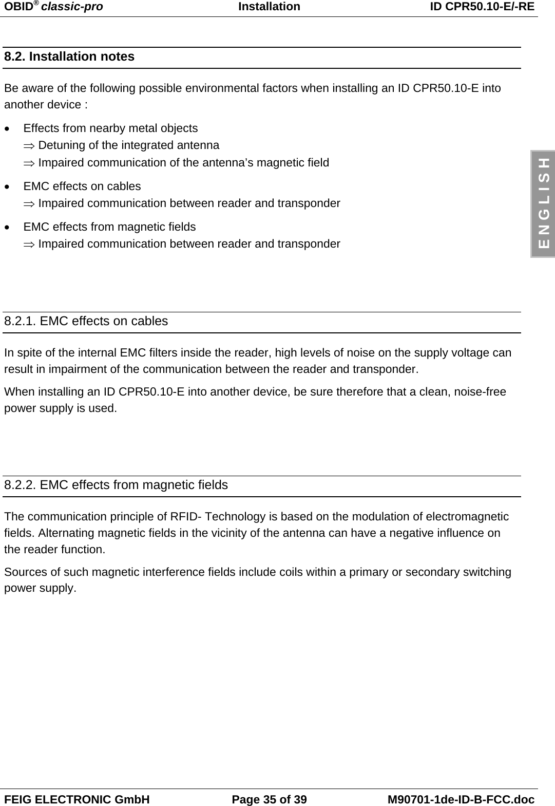
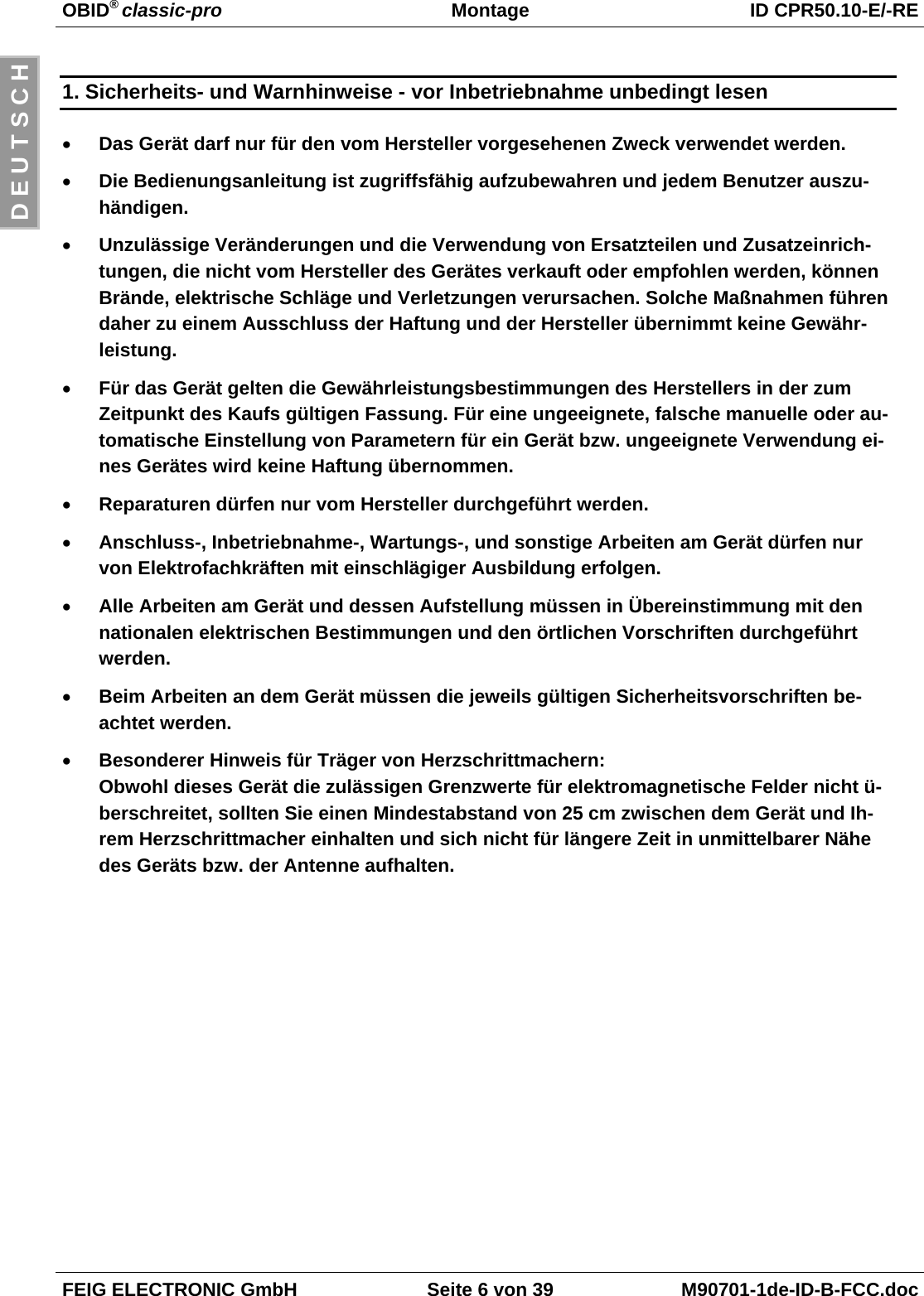
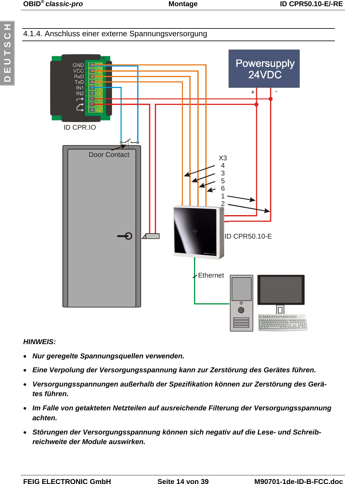
![OBID® classic-pro Installation ID CPR50.10-E/-REFEIG ELECTRONIC GmbH Page 33 of 39 M90701-1de-ID-B-FCC.docE N G L I S H8.1.5. Connections of the extension IO-Board (ID CPR.I/O-A)If a relay or digital inputs are required the optional extension board ID CPR.I/O-A can be con-nected.GNDVCCRxDTxDIN1IN21 2 3 4 5 6 7 8 9X1Fig. 8: ID CPR.I/O-AX1 Pin Symbol Description Connected with Pin x on X3 CPR50.10-E1GND Ground 6 (GND-D)2VCC +5 VDC 5 (VCC)3RxD Receive Input 4 (OUT)4TxD Transmit Output 3 (IN)5 IN1 Digital Input 1 -6 IN2 Digital Input 2 -7Relay NO8Relay COM9Relay NC-8.1.5.1. Relay (ID CPR.I/O-A)The device is equipped with an relay (change-over contact). The connection is executed via theconnectors 7 [NO], 8 [COM] and 9 [NC].8.1.5.2. Digital inputs (ID CPR.I/O-A)The digital inputs [IN1] and [IN2] can only be connected to Ground, connector [GND].Any connection to external voltage might damage the unit!](https://usermanual.wiki/Feig-Electronic/CPR5010/User-Guide-1187286-Page-33.png)