Feig Electronic CPR5010 RFID Reader User Manual
Feig Electronic GmbH RFID Reader
User Manual
MONTAGE
INSTALLATION
preliminary
public (B)
2009-10-07
M90701-1de-ID-B-FCC.doc
OBI
D
®
classic-
p
ro
ID CPR50.10-xE
(-E / -SE / -RE / -SRE)
RFID Reader for ISO/IEC14443-A & -B, NFC and ISO/IEC15693
with Ethernet Interface
(deutsch / english)

OBID® classic-pro Montage ID CPR50.10-E/-RE
FEIG ELECTRONIC GmbH Seite 2 von 39 M90701-1de-ID-B-FCC.doc
D E U T S C H


OBID® classic-pro Montage ID CPR50.10-E/-RE
FEIG ELECTRONIC GmbH Seite 4 von 39 M90701-1de-ID-B-FCC.doc
D E U T S C H
Hinweis
© Copyright 2009 by
FEIG ELECTRONIC GmbH
Lange Straße 4
D-35781 Weilburg-Waldhausen
Tel.: +49 6471 3109-0
http://www.feig.de
Alle früheren Ausgaben verlieren mit dieser Ausgabe ihre Gültigkeit.
Die Angaben in diesem Dokument können ohne vorherige Ankündigung geändert werden.
Weitergabe sowie Vervielfältigung dieses Dokuments, Verwertung und Mitteilung ihres Inhalts sind nicht
gestattet, soweit nicht ausdrücklich zugestanden. Zuwiderhandlung verpflichtet zu Schadenersatz. Alle
Rechte für den Fall der Patenterteilung oder Gebrauchsmuster-Eintragung vorbehalten.
Die Zusammenstellung der Informationen in diesem Dokument erfolgt nach bestem Wissen und Gewissen.
FEIG ELECTRONIC GmbH übernimmt keine Gewährleistung für die Richtigkeit und Vollständigkeit der An-
gaben in diesem Dokument. Insbesondere kann FEIG ELECTRONIC GmbH nicht für Folgeschäden auf
Grund fehlerhafter oder unvollständiger Angaben haftbar gemacht werden. Da sich Fehler, trotz aller Bemü-
hungen nie vollständig vermeiden lassen, sind wir für Hinweise jederzeit dankbar.
Die in diesem Dokument gemachten Installationsempfehlungen gehen von günstigsten Rahmenbedingun-
gen aus. FEIG ELECTRONIC GmbH übernimmt weder Gewähr für die einwandfreie Funktion in system-
fremden Umgebungen, noch für die Funktion eines Gesamtsystems, welches die in diesem Dokument be-
schriebenen Geräte enthält.
FEIG ELECTRONIC weist ausdrücklich darauf hin, dass die in diesem Dokument beschriebenen Geräte
nicht für den Einsatz mit oder in medizinischen Geräten oder für Geräte für lebenserhaltende Maßnahmen
konzipiert sind, bei denen ein Fehler eine Gefahr für menschliches Leben oder für die gesundheitliche Un-
versehrtheit zur Folge haben kann. Der Applikationsdesigner ist dafür verantwortlich geeignete Maßnahmen
zu ergreifen um Gefahren, Schäden oder Verletzungen zu vermeiden.
FEIG ELECTRONIC GmbH übernimmt keine Gewährleistung dafür, dass die in diesem Dokument enthal-
tenden Informationen frei von fremden Schutzrechten sind. FEIG ELECTRONIC GmbH erteilt mit diesem
Dokument keine Lizenzen auf eigene oder fremde Patente oder andere Schutzrechte.
OBID® and OBID i-scan® is a registered trademark of FEIG ELECTRONIC GmbH.
I-CODE® and mifare® is a registered trademark of NXP Electronics N.V.
my-d® is a registered trademark of Infineon Technologies AG
Tag-itTM is a registered trademark of Texas Instruments Incorporated
JewelTM is a trademark of Innovision Research & Technology plc.

OBID® classic-pro Montage ID CPR50.10-E/-RE
FEIG ELECTRONIC GmbH Seite 5 von 39 M90701-1de-ID-B-FCC.doc
D E U T S C H
Inhalt
1. Sicherheits- und Warnhinweise - vor Inbetriebnahme unbedingt lesen 6
2. Lieferumfang 7
2.1. Optionales Zubehör ............................................................................................................7
3. Beschreibung ID CPR50.10-E/-RE 8
4. Montage und Anschluss 9
4.1. Anschluss des Adapter Board.........................................................................................11
4.1.1. LSA Anschluss X2 für TCP/IP Verbindung..................................................................11
4.1.2. Anschluss X3 für Spannungsversorgung und I/O Modul.............................................12
4.1.3. Anschluss über PoE Netzteil .......................................................................................13
4.1.4. Anschluss einer externe Spannungsversorgung .........................................................14
4.1.5. Anschlüsse des externen I/O-Moduls (ID CPR.I/O-A).................................................15
4.1.5.1. Relais (ID CPR.I/O-A)......................................................................................15
4.1.5.2. Digitale Eingänge (ID CPR.I/O-A) ...................................................................15
4.1.5.3. Kommunikationsverbindung zum ID CPR50.10-E...........................................16
4.1.5.4. Spannungsversorgung des ID CPR.I/O-A.......................................................16
4.2. Montagehinweise ..............................................................................................................17
4.2.1. EMV-Beeinflussung über Zuleitungen .........................................................................17
4.2.2. EMV-Beeinflussung über magnetische Felder ............................................................17
5. Technisch Daten ID CPR50.10-E/-RE 18
5.1. Zulassung ..........................................................................................................................19
5.2. Europa (CE)........................................................................................................................19
5.3. Declaration of Conformity for USA..................................................................................19
5.4. Declaration of Conformity for CANADA..........................................................................20
5.5. Abmessungen....................................................................................................................21

OBID® classic-pro Montage ID CPR50.10-E/-RE
FEIG ELECTRONIC GmbH Seite 6 von 39 M90701-1de-ID-B-FCC.doc
D E U T S C H
1. Sicherheits- und Warnhinweise - vor Inbetriebnahme unbedingt lesen
• Das Gerät darf nur für den vom Hersteller vorgesehenen Zweck verwendet werden.
• Die Bedienungsanleitung ist zugriffsfähig aufzubewahren und jedem Benutzer auszu-
händigen.
• Unzulässige Veränderungen und die Verwendung von Ersatzteilen und Zusatzeinrich-
tungen, die nicht vom Hersteller des Gerätes verkauft oder empfohlen werden, können
Brände, elektrische Schläge und Verletzungen verursachen. Solche Maßnahmen führen
daher zu einem Ausschluss der Haftung und der Hersteller übernimmt keine Gewähr-
leistung.
• Für das Gerät gelten die Gewährleistungsbestimmungen des Herstellers in der zum
Zeitpunkt des Kaufs gültigen Fassung. Für eine ungeeignete, falsche manuelle oder au-
tomatische Einstellung von Parametern für ein Gerät bzw. ungeeignete Verwendung ei-
nes Gerätes wird keine Haftung übernommen.
• Reparaturen dürfen nur vom Hersteller durchgeführt werden.
• Anschluss-, Inbetriebnahme-, Wartungs-, und sonstige Arbeiten am Gerät dürfen nur
von Elektrofachkräften mit einschlägiger Ausbildung erfolgen.
• Alle Arbeiten am Gerät und dessen Aufstellung müssen in Übereinstimmung mit den
nationalen elektrischen Bestimmungen und den örtlichen Vorschriften durchgeführt
werden.
• Beim Arbeiten an dem Gerät müssen die jeweils gültigen Sicherheitsvorschriften be-
achtet werden.
• Besonderer Hinweis für Träger von Herzschrittmachern:
Obwohl dieses Gerät die zulässigen Grenzwerte für elektromagnetische Felder nicht ü-
berschreitet, sollten Sie einen Mindestabstand von 25 cm zwischen dem Gerät und Ih-
rem Herzschrittmacher einhalten und sich nicht für längere Zeit in unmittelbarer Nähe
des Geräts bzw. der Antenne aufhalten.

OBID® classic-pro Montage ID CPR50.10-E/-RE
FEIG ELECTRONIC GmbH Seite 7 von 39 M90701-1de-ID-B-FCC.doc
D E U T S C H
2. Lieferumfang
1 x Gehäuseunterteil (Unterputzgehäuse)
1 x Gehäuseoberteil mit Leserelektronik
1 x Aufputzadapter
1 x Anschlussplatine
1 x Linsenschraube Torx 3 x 8 mm, Torx T10 zum Verschließen des Gehäuses
2 x Schneidschraube, Senkkopf 3,2 x 15 mm zur Montage von Gehäuseunterteil
auf Aufputzadapter
2 x Schneidschraube, Senkkopf Schneidschrauben 3,2 x 25 mm zur Wandmontage
1 x Montageanleitung
2.1. Optionales Zubehör
ID CPR.I/O-A: Extension Board mit einem Relais und zwei digitalen Eingängen
OBID® classic-pro Montage ID CPR50.10-E/-RE
FEIG ELECTRONIC GmbH Seite 8 von 39 M90701-1de-ID-B-FCC.doc
D E U T S C H
3. Beschreibung ID CPR50.10-E/-RE
Der ID CPR50.10-E ist ein Mitglied der OBID® classic-pro Reader Familie und unterstützt passive
Transponder gemäß ISO/IEC 14443 Typ A und Typ B, ISO/IEC15693 und kann mit NFC Geräten
(ISO/IEC18092) kommunizieren.
Auf Grund seiner Ethernet Schnittstelle (10BASE-T / 100BASE-T) kann der Reader sehr leicht in
bestehende Netzwerkumgebungen integriert werden.
Als Spannungsversorgung kann ein „Power over Ethernet“ Netzteil gem. IEEE802.3af eingesetzt
werden, wodurch eine einfache Installation und ein Maximum an Zuverlässigkeit erreicht wird. Al-
ternativ kann der ID CPR50.10-E über ein externes 24 V/DC Netzteil versorgt werden.
Der ID CPR50.10-E kann im Polling- oder Notification-Mode betrieben werden. Der Notification-
Mode reduziert den Datenverkehr auf der Ethernet Schnittstelle auf ein Minimum. Im Notification-
Mode sendet der Reader automatisch die gelesenen Transponderdaten an den Host PC, dieser
kann dann einen weiteren Datenaustausch initiieren, fall notwendig.
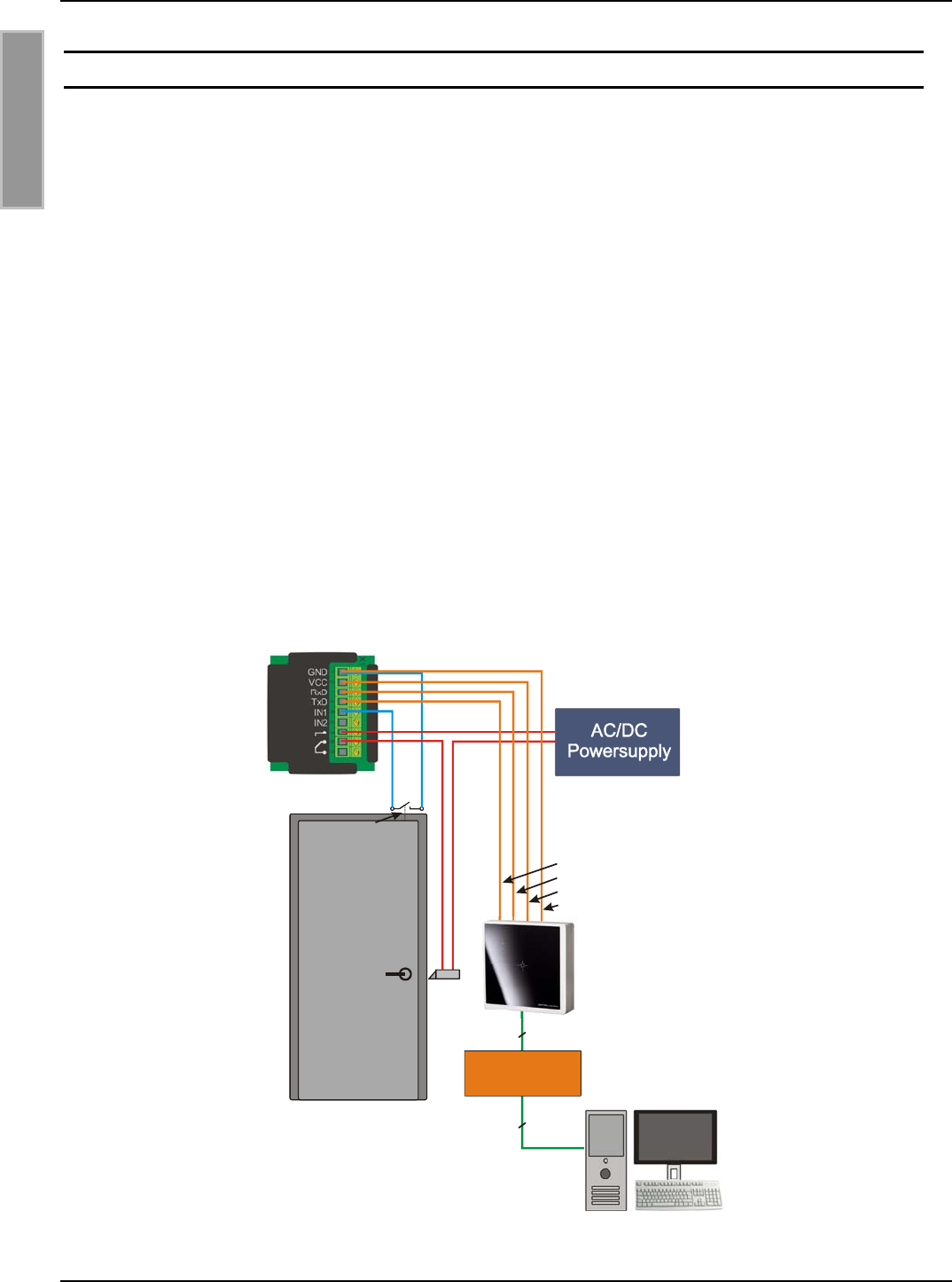
Soll der Reader ID CPR50.10-E ein Relais schalten oder digitale Eingänge überwachen, so kann
das externe I/O Modul ID CPR.I/O-A mit dem Reader verbunden werden. Die entfernte Installation
des Relais garantiert ein Maximum an Sicherheit wenn das Relais z.B. als Türöffner verwendet
wird. Dazu kann das I/O Modul in dem geschützten Innenbereich des Gebäudes installiert werden.
Alternativ kann der Reader ID CPR50.10-RE mit einem internen Relais verwendet werden.
PoE Power Supply
(IEEE802.3af)
Ethernet
Ethernet
ID CPR.IO
ID CPR50.10-E
Door Contact
X3
4
3
5
6
Abbildung 1:Installation für ID CPR50.10-E mit optionalem I/O Extension Board ID CPR.I/O-A
OBID® classic-pro Montage ID CPR50.10-E/-RE
FEIG ELECTRONIC GmbH Seite 9 von 39 M90701-1de-ID-B-FCC.doc
D E U T S C H
4. Montage und Anschluss
Der Leser ist für die Wandmontage auf 60 mm Unterputzdosen oder für Aufputzmontage vorgese-
hen.
HINWEISE:
• Der Reader sollte nicht direkt auf leitende Materialien wie Metallflächen, Metallgitter (Ar-
mierung) oder metallisierte Oberflächen montiert werden, da diese Flächen eine Reduzie-
rung der Lesereichweite bewirken..
Bei der Montage auf Metalloberfläche sollte die Montage mit dem Aufputzadapter erfol-
gen, damit ein ausreichender Abstand zwischen Leser und Metalloberfläche hergestellt
ist.
• Beim Einbau des Readers in einen Metallrahmen ist darauf zu achten , dass ein Min-
destabstand vom ca. 25mm zum Reader eingehalten wird.
• Geschlossen Metallrahmen müssen an einer Stelle unterbrochen werden.
• Der räumliche Abstand zu benachbarten Lesern gleicher Bauart sollte 30 cm nicht unter-
schreiten.
• Vor der endgültigen Installation sollte der geplante Installationsort auf seine Tauglichkeit
geprüft werden.
X1
1
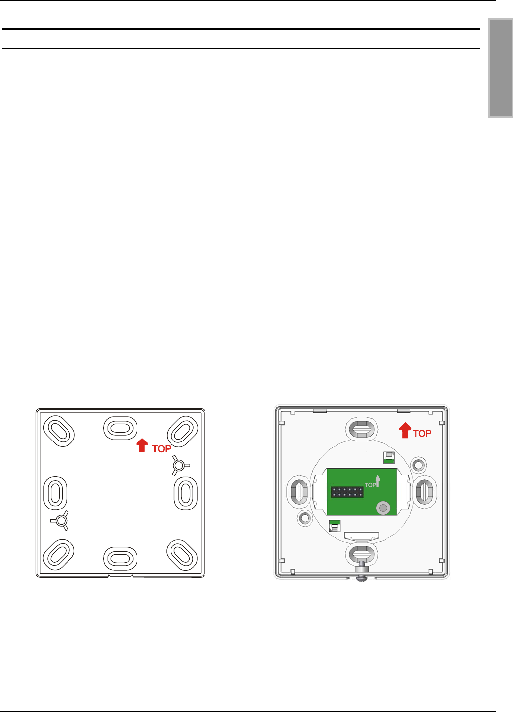
Abbildung 2: Aufputzadapter
Montageausrichtung,
(⇑ TOP) nach oben
Abbildung 3: Unterputzgehäuse
Montageausrichtung,
(⇑ TOP) nach oben
OBID® classic-pro Montage ID CPR50.10-E/-RE
FEIG ELECTRONIC GmbH Seite 10 von 39 M90701-1de-ID-B-FCC.doc
D E U T S C H
1. Montageort auswählen:
Die Montage sollte auf einem möglichst ebenen Untergrund erfolgen.
2. Anschluss:
siehe Kapitel: 4.1. Anschluss des Adapter Board
3. Wandmontage:
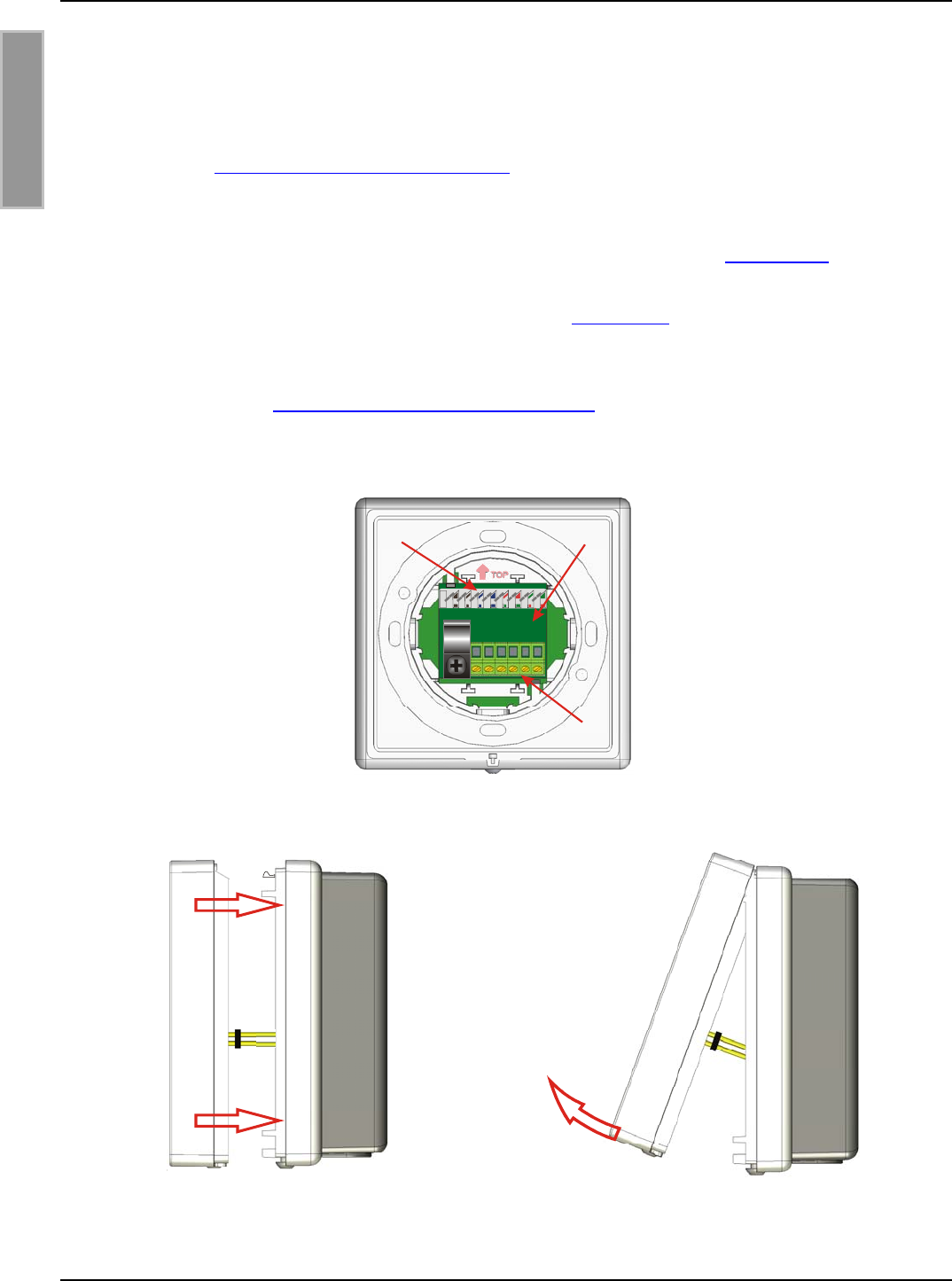
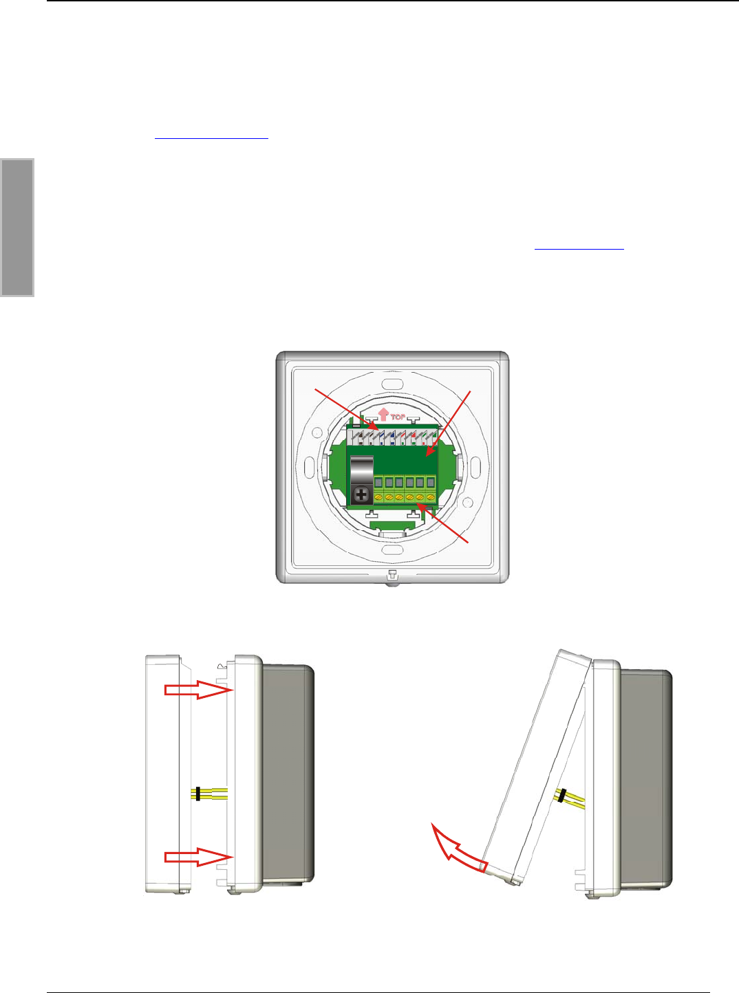
• Anschlussplatine von hinten in das Gehäuseunterteil einrasten (siehe: Abbildung 4).
• Gehäuseunterteil auf der Wand verschrauben.
Montagerichtung ⇑ TOP beachten, siehe Kapitel: 4. Montage
• Gehäuseoberteil gerade auf das Gehäuseunterteil aufstecken und einrasten.
Stiftleiste X1 der Leserelektronik sauber in Buchsenleiste X1 der Anschlussplatine (1)
einführen! Siehe Abbildung 5: Gehäusedeckel stecken
• Gehäuse von unten mit Schraube Torx 3x8 mm (Torx T10) verschließen.
• Schutzfolie von Frontscheibe entfernen.
88
B
A7
85436412
X
3
X2 (1)
Abbildung 4: Rückansicht mit eingerasteter Anschlussplatine (1)
Abbildung 5: Gehäusedeckel stecken Abbildung 6: Gehäusedeckel öffnen
OBID® classic-pro Montage ID CPR50.10-E/-RE
FEIG ELECTRONIC GmbH Seite 11 von 39 M90701-1de-ID-B-FCC.doc
D E U T S C H
4.1. Anschluss des Adapter Board
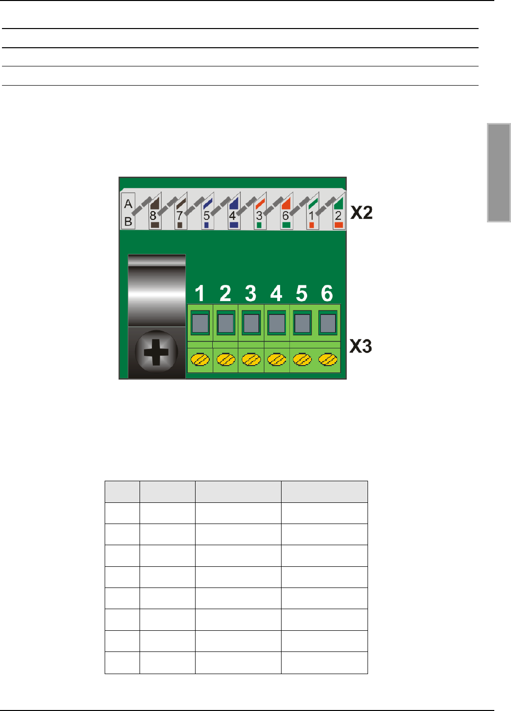
4.1.1. LSA Anschluss X2 für TCP/IP Verbindung
Der Anschluss des ID CPR50.10-E an das Ethernet und das PoE Netzteil erfolgt über den LSA
Anschluss X2 auf der Adapter Platine welche in dem Readergehäuse eingerastet wird.
Für das Auflegen der CAT5 Kabel auf der LSA Anschlussleiste ist ein entsprechendes LSA-Auflege-
werkzeug (punch down tool ) zu verwenden.
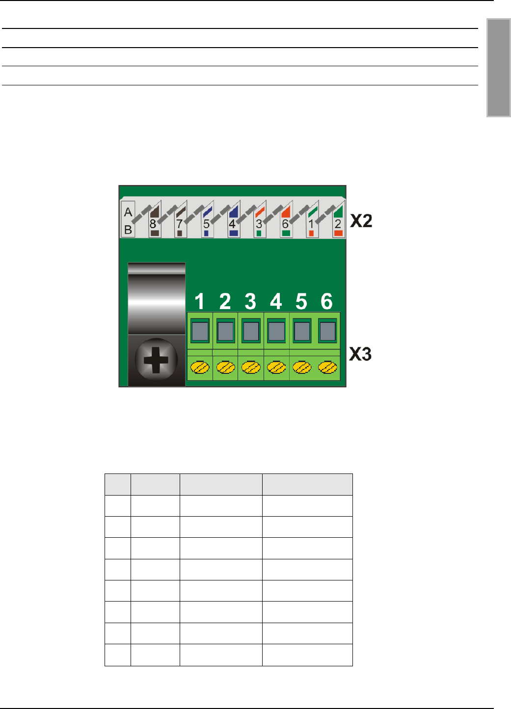
Abbildung 7: ID CPR50.10-E Adapter Platine mit LSA Anschlussleiste X2
Es gibt bei CAT5 zwei Belegungen EIA/TIA T568A und EIA/TIA T568B. Die entsprechende Farb-
codierung ist in der folgenden Tabelle dargestellt.
X2 Signal EIA/TIA T568A EIA/TIA T568B
1Tx D1+ Weiß/Grün Weiß/Orange
2Tx D1- Grün Orange
3Rx D2+ Weiß/Orange Weiß/Grün
4BI D3+ Blau Blau
5BI D3- Weiß/Blau Weiß/Blau
6Rx D2- Orange Grün
7BI D4+ Weiß/Braun Weiß/Braun
8BI D4- Braun Braun

OBID® classic-pro Montage ID CPR50.10-E/-RE
FEIG ELECTRONIC GmbH Seite 12 von 39 M90701-1de-ID-B-FCC.doc
D E U T S C H
4.1.2. Anschluss X3 für Spannungsversorgung und I/O Modul
Der Anschluss X3 wird für die externe Spannungsversorgung des ID CPR50.10-E verwendet, falls
keine PoE Versorgung zur Verfügung steht. Siehe 4.1.4. Anschluss einer externe Spannungsver-
sorgung
Außerdem kann bei dem Reader ID CPR50.10-E über den Anschluss X3 das externe I/O-Modul ID
CPR.I/O-A angeschlossen werden. Siehe 4.1.5. Anschlüsse des externen I/O-Moduls (ID CPR.I/O-A)
Alternativ kann der Reader ID CPR50.10-RE mit einem internen Relais benutzt werden.
X3 Signal Beschreibung
ID CPR50.10-E
Beschreibung
ID CPR50.10-RE
1VIN-EXT+ * Externe DC + Externe DC +
2GND-EXT- * Externe DC - Externe DC -
3TxD Sendesignal für ID CPR.I/O-A internes Relais COM
4RxD Empfangssignal für ID CPR.I/O-A internes Relais NO
5VCC DC + für ID CPR.I/O-A -
6GND-D DC – für ID CPR.I/O-A -
* Die Versorgung über ein externes Netzteil ist nicht notwendig wenn der Reader über ein
PoE-Netzteil versorgt wird, in dem Fall bleiben die Anschlüsse VIN-Ext+ und GND-EXT- frei.
OBID® classic-pro Montage ID CPR50.10-E/-RE
FEIG ELECTRONIC GmbH Seite 13 von 39 M90701-1de-ID-B-FCC.doc
D E U T S C H
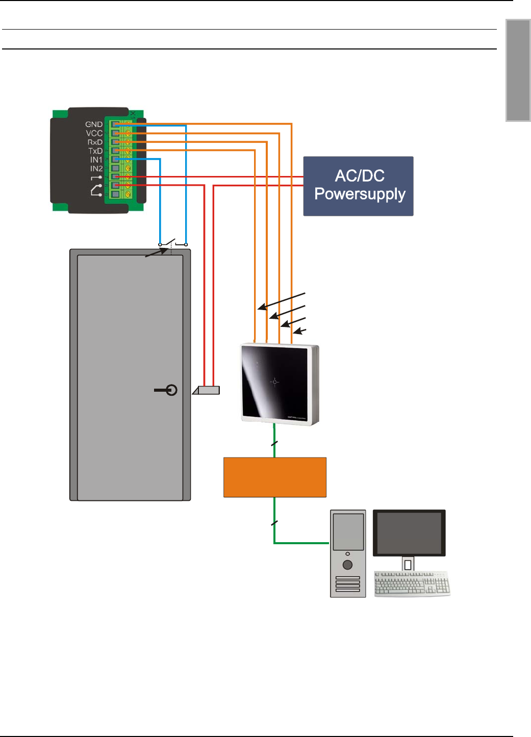
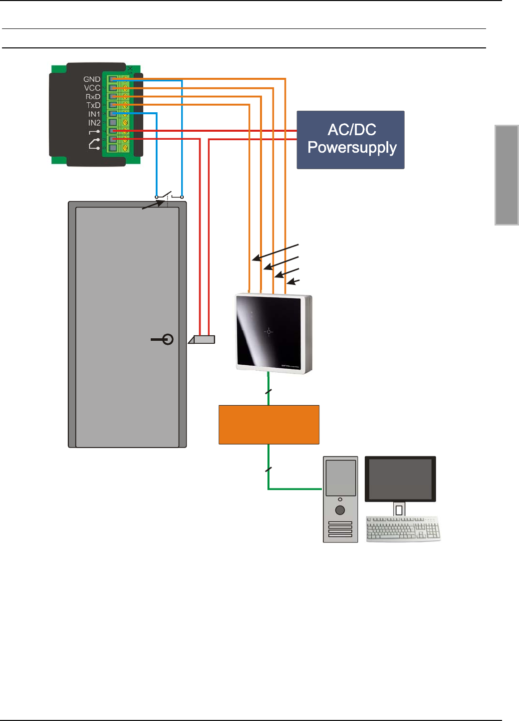
4.1.3. Anschluss über PoE Netzteil
In diesem Verdrahtungsbeispiel wird der Reader über ein PoE Netzteil mit Spannung versorgt.
PoE Power Supply
(IEEE802.3af)
Ethernet
Ethernet
ID CPR.IO
ID CPR50.10-E
Door Contact
X3
4
3
5
6
OBID® classic-pro Montage ID CPR50.10-E/-RE
FEIG ELECTRONIC GmbH Seite 14 von 39 M90701-1de-ID-B-FCC.doc
D E U T S C H
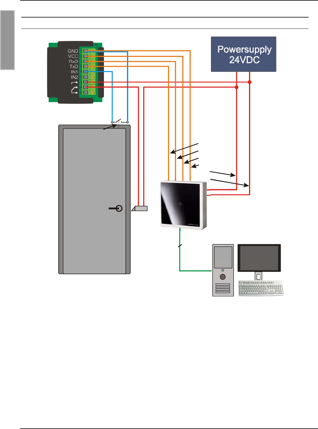
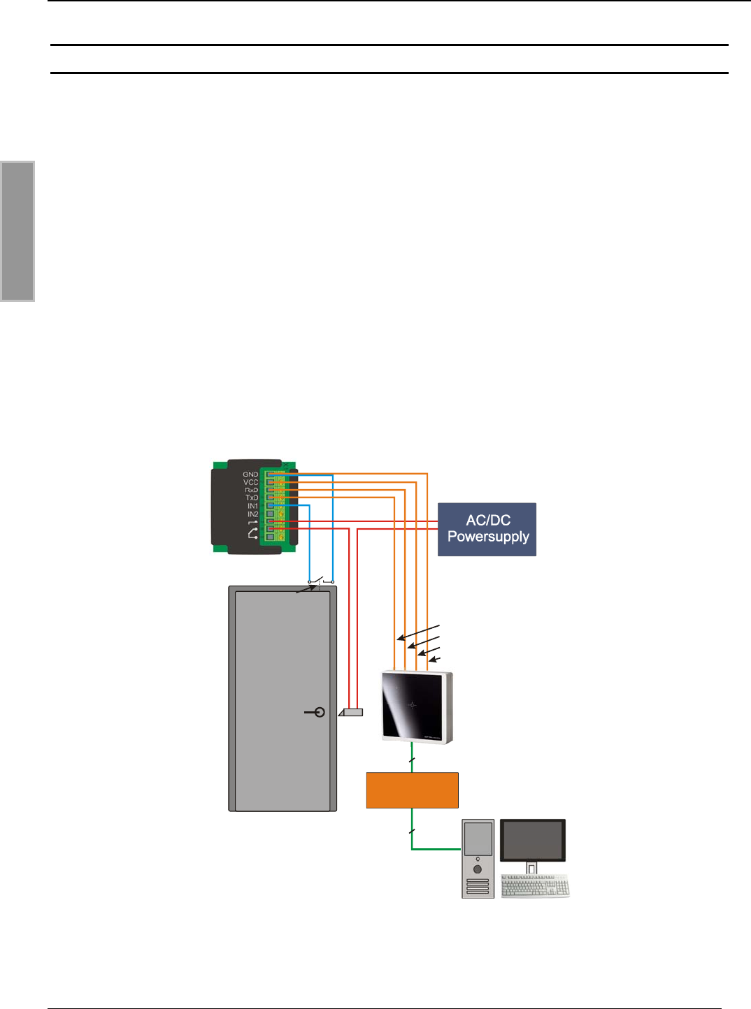
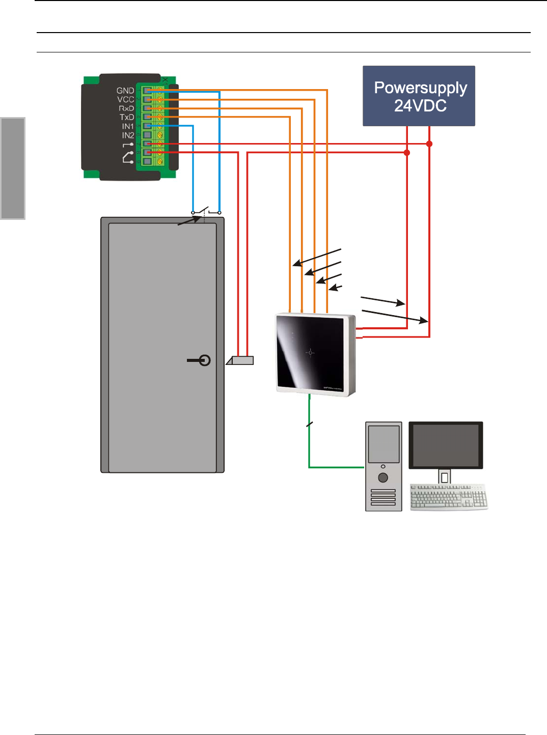
4.1.4. Anschluss einer externe Spannungsversorgung
Ethernet
ID CPR.IO
ID CPR50.10-E
Door Contact X3
4
3
5
6
1
2
+-
HINWEIS:
• Nur geregelte Spannungsquellen verwenden.
• Eine Verpolung der Versorgungsspannung kann zur Zerstörung des Gerätes führen.
• Versorgungsspannungen außerhalb der Spezifikation können zur Zerstörung des Gerä-
tes führen.
• Im Falle von getakteten Netzteilen auf ausreichende Filterung der Versorgungsspannung
achten.
• Störungen der Versorgungsspannung können sich negativ auf die Lese- und Schreib-
reichweite der Module auswirken.
OBID® classic-pro Montage ID CPR50.10-E/-RE
FEIG ELECTRONIC GmbH Seite 15 von 39 M90701-1de-ID-B-FCC.doc
D E U T S C H
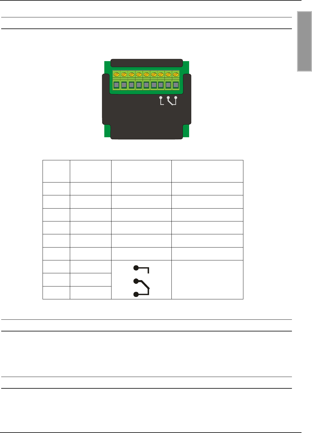
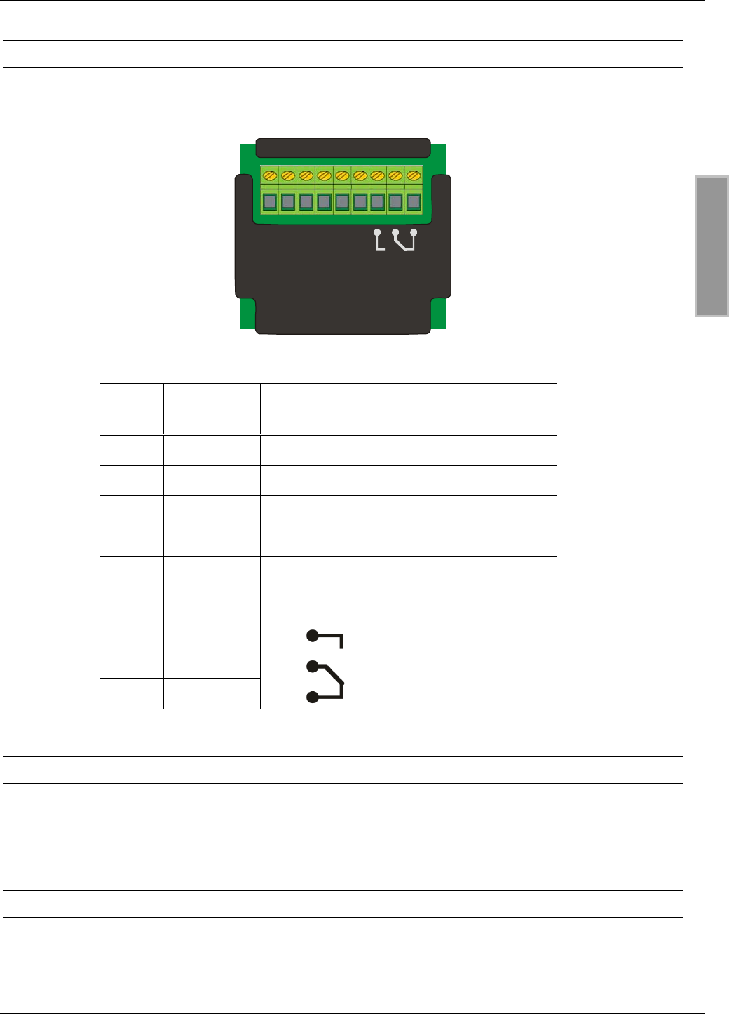
4.1.5. Anschlüsse des externen I/O-Moduls (ID CPR.I/O-A)
Wenn ein Relais oder digitaler Eingang benötigt wird, kann das optionale externe Erweiterungs-
modul ID CPR.I/O-A angeschlossen werden.
GND
VCC
RxD
TxD
IN1
IN2
1 2 3 4 5 6 7 8 9
X1
Abbildung 8: ID CPR.I/O-A
X1 Pin Kurzzeichen Beschreibung Verbunden mit Pin x
on X3 CPR50.10-E
1GND Ground 6 (GND-D)
2VCC +5 VDC 5 (VCC)
3RxD Receive Input 4 (OUT)
4TxD Transmit Output 3 (IN)
5 IN1 Digitaler Eingang 1 -
6 IN2 Digitaler Eingang 2 -
7Relais NO
8Relais COM
9Relais NC
-
4.1.5.1. Relais (ID CPR.I/O-A)
Das ID CPR.I/O-A Module verfügt über ein Relais mit einem Wechselkontakt. Der Anschluss er-
folgt über die Klemmen 7 [NO], 8 [COM] und 9 [NC].
4.1.5.2. Digitale Eingänge (ID CPR.I/O-A)
Die digitalen Eingänge [IN1] und [IN2]) dürfen nur gegen Ground, Klemme [GND] geschaltet wer-
den.
Eine Beschaltung mit Fremdspannung kann zur Zerstörung des Gerätes führen!
OBID® classic-pro Montage ID CPR50.10-E/-RE
FEIG ELECTRONIC GmbH Seite 16 von 39 M90701-1de-ID-B-FCC.doc
D E U T S C H
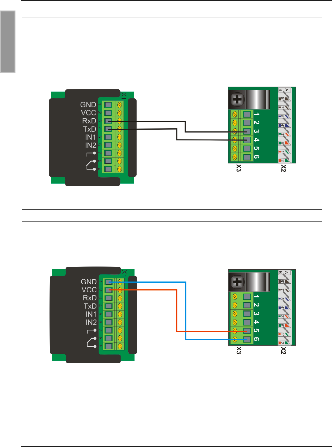
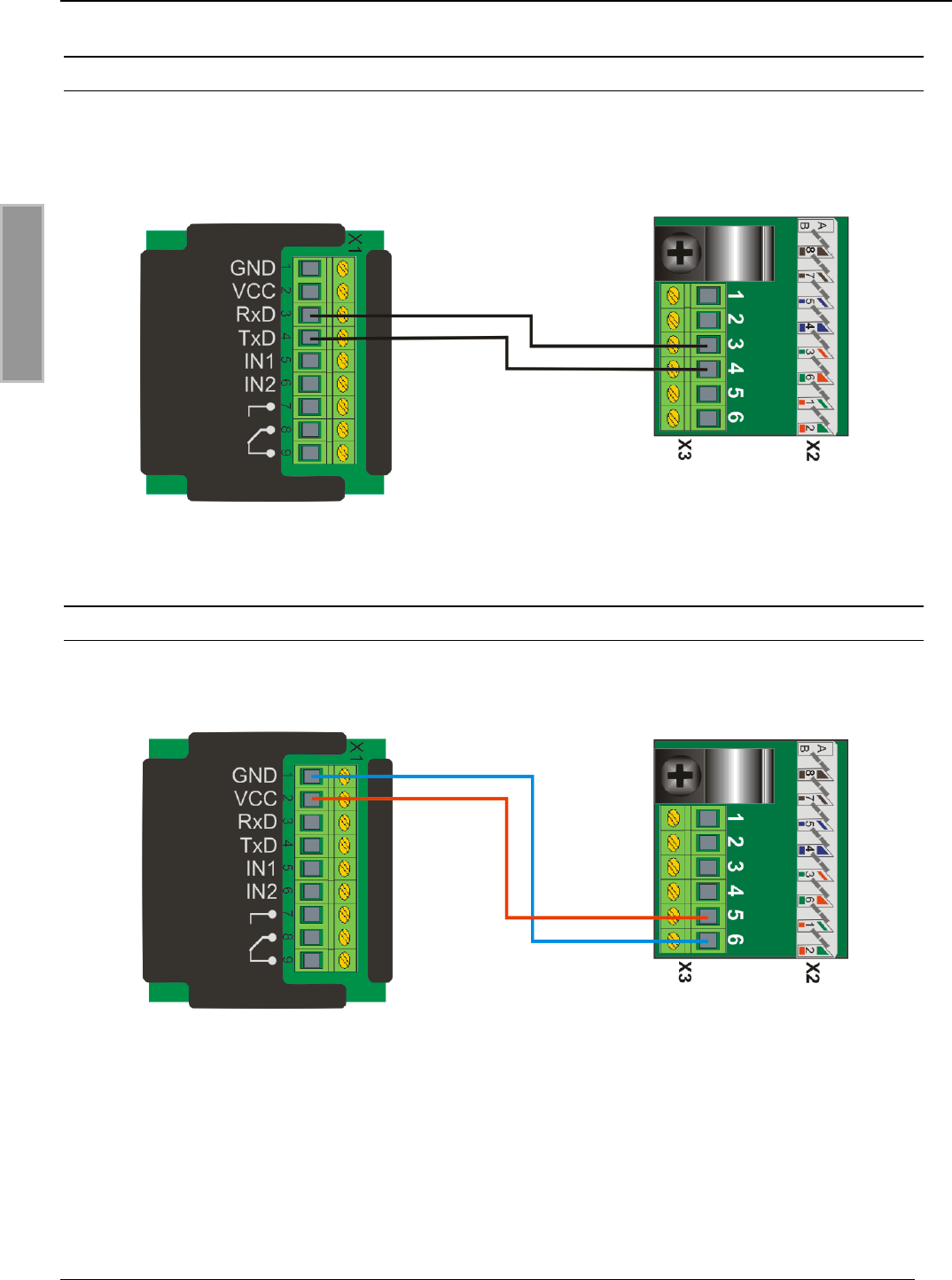
4.1.5.3. Kommunikationsverbindung zum ID CPR50.10-E
Die Ansteuerung des externen I/O Moduls erfolgt über eine verschlüsselte, serielle Schnittstelle.
Die Kommunikationsverbindung zum Reader ID CPR50.10-E wird über die Anschlüsse RxD (Pin3)
und TxD (Pin4) hergestellt.
Abbildung 9: Kommunikationsverbindung zum Reader ID CPR50.10-E
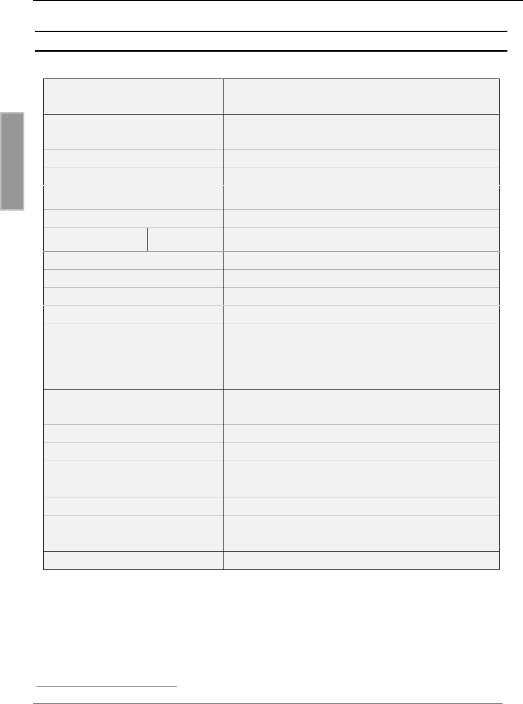
4.1.5.4. Spannungsversorgung des ID CPR.I/O-A
Die Spannungsversorgung des externen I/O Moduls erfolgt ausschließlich über den Reader
ID CPR50.10-E über die Anschlüsse VCC (+) und GND (-).
Abbildung 10: Spannungsversorgung des ID CPR.I/O-A

OBID® classic-pro Montage ID CPR50.10-E/-RE
FEIG ELECTRONIC GmbH Seite 17 von 39 M90701-1de-ID-B-FCC.doc
D E U T S C H
4.2. Montagehinweise
Folgende mögliche Beeinflussungen durch die Umgebung sollten beim Einbau eines
ID CPR50.10-E in ein anderes Gerät beachtet werden:
• Beeinflussung durch metallische Umgebung
⇒ Verstimmung der integrierten Antenne
⇒ Beeinträchtigung der Ausbreitung des magnetischen Feldes der Antenne
• EMV-Beeinflussung über Zuleitungen
⇒ Beeinträchtigung der Kommunikation zwischen Reader und Transponder
• EMV-Beeinflussungen über magnetische Felder
⇒ Beeinträchtigung der Kommunikation zwischen Reader und Transponder
4.2.1. EMV-Beeinflussung über Zuleitungen
Trotz internen EMV-Filter können starke Störungen auf der Spannungsversorgung zu Beeinträchti-
gungen der Kommunikation zwischen Reader und Transponder führen. Dabei wird vor allem der
Empfang des Transponders gestört.
Beim Einbau sollte daher auf eine möglichst saubere, störfreie Spannungsversorgung geachtet
werden.
4.2.2. EMV-Beeinflussung über magnetische Felder
Das Kommunikationsprinzip von RFID-Technik basiert auf der Modulation eines elektromagneti-
schen Feldes. Magnetische Wechselfelder in der Nähe der Antenne können sich negativ auf die
Funktion des Readers auswirken.
Zu den Quellen solcher magnetischen Störfelder gehören zum Beispiel Spulen innerhalb eines
primär oder sekundär getakteten Netzteils.

OBID® classic-pro Montage ID CPR50.10-E/-RE
FEIG ELECTRONIC GmbH Seite 18 von 39 M90701-1de-ID-B-FCC.doc
D E U T S C H
5. Technisch Daten ID CPR50.10-E/-RE
• Unterputzgehäuse
Abmessungen (L x B x H)
Farbe
84 x 84 x 22 mm
Korpus: weiß / Frontscheibe: schwarz
• Aufputzadapter
Abmessungen (L x B x H)
Farbe
77,7 x 77,7 x 18,0 mm
hellgrau
Gewicht ca. 150 g
Schutzart IP 54
Spannungsversorgung Alternativ: - Power over Ethernet (PoE) IEEE802.3af (44 V to 54 V DC)
- Externe Spannungsversorgung 24VDC ±10%
Leistungsaufnahme max. 2,6 W
Temperaturbereich Betrieb
Lagerung -20 °C bis +70 °C
-40 °C bis +85 °C
relative Luftfeuchte 95 % nicht betauend
Antenne intern ca. 70 x 70 mm
Betriebsfrequenz 13,56 MHz
Sendeleistung 250 mW ± 2 dB
RF-Interface ISO14443-A, ISO14443-B, NFC1, ISO15693
Unterstützte Transpondertypen
z.B.: mifare® classic (mini, 1k, 4k), mifare® UltraLight,
mifare® DESfire, Smart MX, my-d® proximity, SLE44R35S,
JewelTM, SLE66CL, ST19XR34, RF360, I•Code SLI, Tag-It
HFI, my-d vicintiy, STM LRI512, etc.
LED Blau (Power und TCP/IP socket Verbindung)
Grün (angesteuert vom Host)
Rod (angesteuert vom Host)
Summer integriert
Anschluss TCP/IP LSA Terminal
Relais (extern) ID CPR50.10-E 1 Relais, Anschluss über ID CPR.I/O-A
Relais (intern) ID CPR50.10-RE 1 Relais, internes Relais
Digitaler Eingang ID CPR50.10-E 2 Digitale Eingänge, Anschluss über ID CPR.I/O-A
Interface Ethernet 10BASE-T/100BASE-TX
automatik MDI/MDI-X cross over correction
TCP/IP protocol
EEPROM für Konfigurationsparameter (1 Million Schreibzyklen)
1 NFC: Type 1, Type 2 and Type 4 in read/write and NFC card emulation mode
OBID® classic-pro Montage ID CPR50.10-E/-RE
FEIG ELECTRONIC GmbH Seite 19 von 39 M90701-1de-ID-B-FCC.doc
D E U T S C H
5.1. Zulassung
Funk
- Europa
- USA EN 300 330
FCC 47 CFR Part 15
EMV EN 300 489
Sicherheit
- Niederspannung
- Human Exposure EN 60950
EN 50364
Umwelt RoHS - 2002/95/EC
WEEE - 2002/96/EC
5.2. Europa (CE)
Die Funkanlage entspricht, bei bestimmungsgemäßer Verwendung den grundlegenden Anforde-
rungen des Artikels 3 und den übrigen einschlägigen Bestimmungen der R&TTE Richtlinie
1999/5/EG vom März 99.
Equipment Classification gemäß ETSI EN 300 330: Class 2
5.3. Declaration of Conformity for USA
This device complies with Part 15 of the FCC Rules. Operation is subject to the following two conditions:
(1) This device may not cause harmful interference, and (2) this device must accept any interference re-
ceived, including interference that may cause undesired operation.
Usually this is followed by the following FCC caution:
Any changes or modifications not expressly approved by the party responsible for compliance could void the
user's authority to operate this equipment.
NOTE: This equipment has been tested and found to comply with the limits for a Class B digital device, pur-
suant to Part 15 of the FCC Rules. These limits are designed to provide reasonable protection against
harmful interference in a residential installation. This equipment generates, uses and can radiate radio fre-
quency energy and, if not installed and used in accordance with the instructions, may cause harmful interfer-
ence to radio communications. However, there is no guarantee that interference will not occur in a particular
installation. If this equipment does cause harmful interference to radio or television reception, which can be
determined by turning the equipment off and on, the user is encouraged to try to correct the interference by
one or more of the following measures:
- Reorient or relocate the receiving antenna.
- Increase the separation between the equipment and receiver.
- Connect the equipment into an outlet on a circuit different from that to which the receiver is connected.
- Consult the dealer or an experienced radio/TV technician for help.

OBID® classic-pro Montage ID CPR50.10-E/-RE
FEIG ELECTRONIC GmbH Seite 20 von 39 M90701-1de-ID-B-FCC.doc
D E U T S C H
5.4. Declaration of Conformity for CANADA
Operation is subject to the following two conditions:
(1) this device may not cause interference, and (2) this device must accept any interference, including inter-
ference that may cause undesired operation of the device.
Usually this is followed by the following RSS caution:
Any changes or modifications not expressly approved by the party responsible for compliance could void the
user's authority to operate this equipment.
OBID® classic-pro Montage ID CPR50.10-E/-RE
FEIG ELECTRONIC GmbH Seite 21 von 39 M90701-1de-ID-B-FCC.doc
D E U T S C H
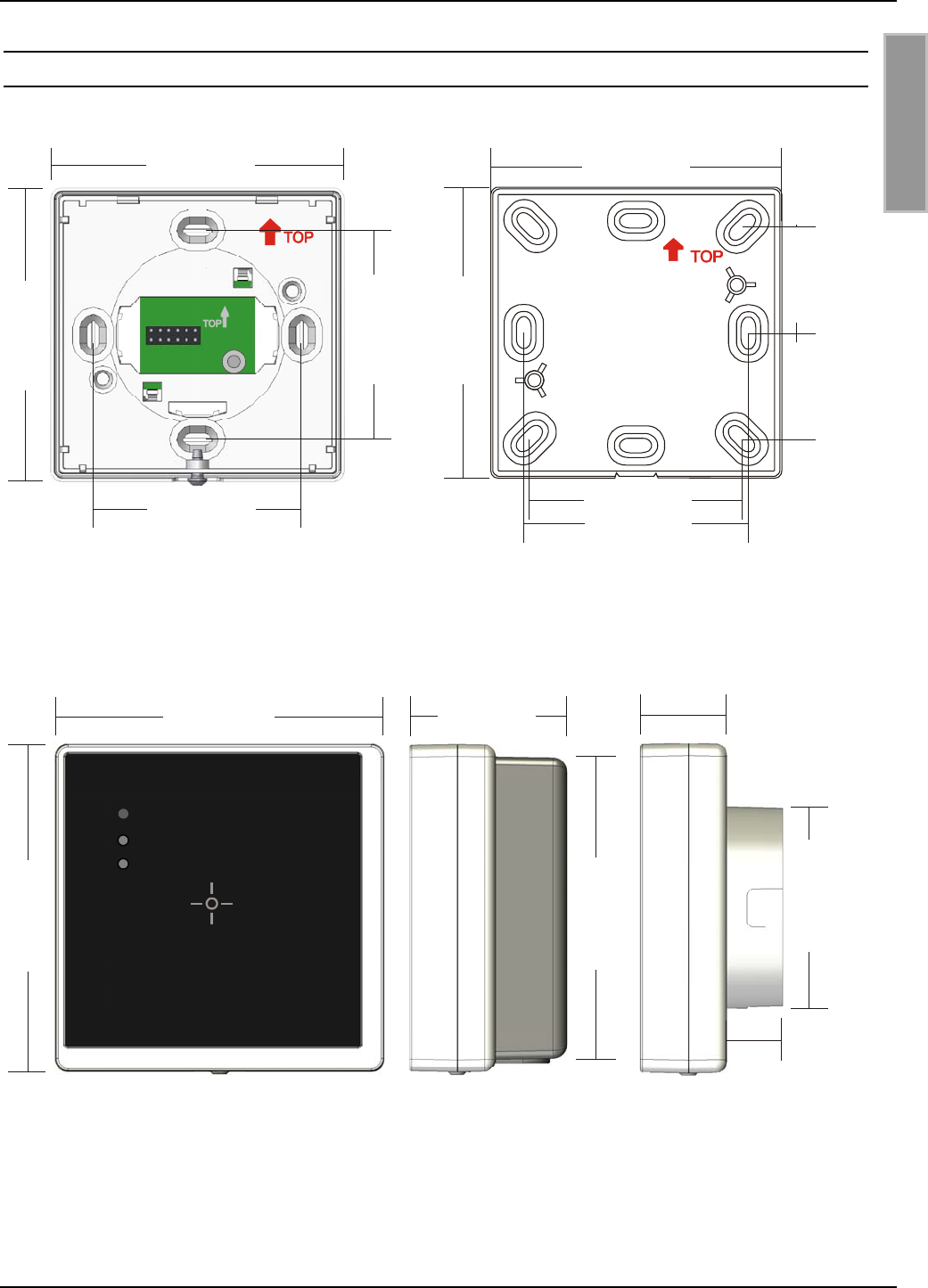
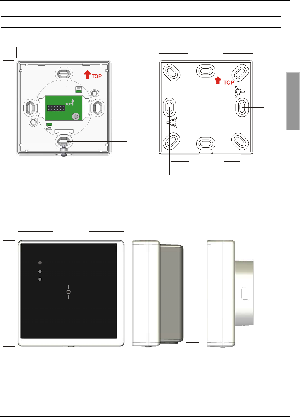
5.5. Abmessungen
X1
1
84,2 mm
84,2 mm
60,0 mm
60,0 mm
77,7 mm
56,8 mm
60,0 mm
28,4 mm 28,4 mm
77,7 mm
Abbildung 11: Unterputzgehäuse
Befestigungsmasse
Abbildung 12: Aufputzadapter
Befestigungsmasse
84,2 mm
84,2 mm
77,7 mm
40 mm
22 mm
51,5 mm
14,0 mm
Abbildung 13: Gehäuseabmessungen

OBID® classic-pro Installation ID CPR50.10-E/-RE
FEIG ELECTRONIC GmbH Page 22 of 39 M90701-1de-ID-B-FCC.doc
E N G L I S H
Note
© Copyright 2009 by
FEIG ELECTRONIC GmbH
Lange Strasse 4
D-35781 Weilburg-Waldhausen
Tel.: +49 6471 3109-0
http://www.feig.de
With the edition of this document, all previous editions become void. Indications made in this manual may be
changed without previous notice.
Copying of this document, and giving it to others and the use or communication of the contents thereof are
forbidden without express authority. Offenders are liable to the payment of damages. All rights are reserved
in the event of the grant of a patent or the registration of a utility model or design.
Composition of the information in this document has been done to the best of our knowledge. FEIG
ELECTRONIC GmbH does not guarantee the correctness and completeness of the details given in this
manual and may not be held liable for damages ensuing from incorrect or incomplete information. Since,
despite all our efforts, errors may not be completely avoided, we are always grateful for your useful tips.
The instructions given in this manual are based on advantageous boundary conditions. FEIG ELECTRONIC
GmbH does not give any guarantee promise for perfect function in cross environments and does not give
any guaranty for the functionality of the complete system which incorporates the subject of this document.
FEIG ELECTRONIC call explicit attention that devices which are subject of this document are not designed
with components and testing methods for a level of reliability suitable for use in or in connection with surgical
implants or as critical components in any life support systems whose failure to perform can reasonably be
expected to cause significant injury to a human. To avoid damage, injury, or death, the user or application
designer must take reasonably prudent steps to protect against system failures.
FEIG ELECTRONIC GmbH assumes no responsibility for the use of any information contained in this
document and makes no representation that they free of patent infringement. FEIG ELECTRONIC GmbH
does not convey any license under its patent rights nor the rights of others.
OBID® and OBID i-scan® is a registered trademark of FEIG ELECTRONIC GmbH.
I-CODE® and mifare® is a registered trademark of NXP Electronics N.V.
my-d® is a registered trademark of Infineon Technologies AG
Tag-itTM is a registered trademark of Texas Instruments Incorporated
JewelTM is a trademark of Innovision Research & Technology plc.

OBID® classic-pro Installation ID CPR50.10-E/-RE
FEIG ELECTRONIC GmbH Page 23 of 39 M90701-1de-ID-B-FCC.doc
E N G L I S H
Contents
6. Safety Instructions / Warning - Read before start-up !.....................................................24
6.1. System delivery contents.................................................................................................25
6.2. Optional Accessories........................................................................................................25
7. Characterization ID CPR50.10-E/-RE 26
8. Installation 27
8.1. Connections.......................................................................................................................29
8.1.1. LSA Connection X2 for TCP/IP Interface.....................................................................29
8.1.2. Connection X3 for Power supply and I/O Module.......................................................30
8.1.3. Connection with PoE Supply ........................................................................................31
8.1.4. Connection with External Powered Supply..................................................................32
8.1.5. Connections of the extension IO-Board (ID CPR.I/O-A)..............................................33
8.1.5.1. Relay (ID CPR.I/O-A) ......................................................................................33
8.1.5.2. Digital inputs (ID CPR.I/O-A)...........................................................................33
8.1.5.3. Communication connection to the Reader ID CPR50.10-E.............................34
8.1.5.4. Power supply of the ID CPR.I/O-A ..................................................................34
8.2. Installation notes...............................................................................................................35
8.2.1. EMC effects on cables.................................................................................................35
8.2.2. EMC effects from magnetic fields................................................................................35
9. Technical Data of the Reader Family ID CPR50.10-E/-RE 36
9.1. Approval.............................................................................................................................37
9.2. Europe (CE)........................................................................................................................37
9.3. Declaration of Conformity for USA..................................................................................37
9.4. Declaration of Conformity for CANADA..........................................................................38
9.5. Dimensions........................................................................................................................39

OBID® classic-pro Installation ID CPR50.10-E/-RE
FEIG ELECTRONIC GmbH Page 24 of 39 M90701-1de-ID-B-FCC.doc
E N G L I S H
6. Safety Instructions / Warning - Read before start-up !
• The device may only be used for the intended purpose designed by for the
manufacturer.
• The operation manual should be conveniently kept available at all times for each user.
• Unauthorised changes and the use of spare parts and additional devices which have not
been sold or recommended by the manufacturer may cause fire, electric shocks or
injuries. Such unauthorised measures shall exclude any liability by the manufacturer.
• The liability-prescriptions of the manufacturer in the issue valid at the time of purchase
are valid for the device. The manufacturer shall not be held legally responsible for
inaccuracies, errors, or omissions in the manual or automatically set parameters for a
device or for an incorrect application of a device.
• Repairs may only be executed by the manufacturer.
• Installation, operation, and maintenance procedures should only be carried out by
qualified personnel.
• Use of the device and its installation must be in accordance with national legal
requirements and local electrical codes .
• When working on devices the valid safety regulations must be observed.
• Special advice for carriers of cardiac pacemakers:
Although this device doesn't exceed the valid limits for electromagnetic fields you
should keep a minimum distance of 25 cm between the device and your cardiac pace-
maker and not stay in an immediate proximity of the device respective the antenna for
some time.

OBID® classic-pro Installation ID CPR50.10-E/-RE
FEIG ELECTRONIC GmbH Page 25 of 39 M90701-1de-ID-B-FCC.doc
E N G L I S H
6.1. System delivery contents
1 x Bottom part of housing (concealed casing)
1 x Housing upper part with Reader electronic
1 x Surface mounting adapter
1 x Connection board
1 x Screw Torx 3 x 8 mm, Torx T10 for closing the housing
2 x Thread cutting screws 3,2 x 15 mm for mounting the surface adapter
2 x Thread cutting screw 3,2 x 25 mm for wall mounting
1 x Installation instruction
6.2. Optional Accessories
ID CPR.I/O-A: Extension Board with one Relay and two digital Inputs.
OBID® classic-pro Installation ID CPR50.10-E/-RE
FEIG ELECTRONIC GmbH Page 26 of 39 M90701-1de-ID-B-FCC.doc
E N G L I S H
7. Characterization ID CPR50.10-E/-RE
The ID CPR50.10-E is a member of the OBID® classic-pro reader family and supports transponder
chips according ISO/IEC 14443 type A and type B as well as transponder chips according ISO/IEC
15693 and is able to communicate with NFC devices.
Because of it's Ethernet interface according 10BASE-T / 100BASE-T standard the ID CPR50.10-E
is well suited for easy integration in an existing LAN environment. The integrated power over
Ethernet (PoE) power supply guaranties a maximum on reliability and easy installation with stan-
dardized PoE power supply's.
The ID CPR50.10-E can work in polling mode or in notification mode which reduces the necessary
data traffic with the reader to a minimum. In notification mode the host will be informed by a notifi-
cation message if a transponder was detected by the reader and can start the further data ex-
change with this transponder if required.If the reader ID CPR50.10-E shall be used to switch a re-
lay or to monitor digital inputs the remote I/O-board (ID CPR.I/O-A) can be connected to the
reader. The remote installation of the relay guarantees a maximum on security if the relay shall
switch e.g. a door opener, because it can placed at the interior of the building.
Optionally the reader ID CPR50.10-RE with one internal relay can be used.
PoE Power Supply
(IEEE802.3af)
Ethernet
Ethernet
ID CPR.IO
ID CPR50.10-E
Door Contact
X3
4
3
5
6
Fig. 1: Installation diagram for ID CPR50.10-E with optional I/O extension board ID CPR.I/O-A

OBID® classic-pro Installation ID CPR50.10-E/-RE
FEIG ELECTRONIC GmbH Page 27 of 39 M90701-1de-ID-B-FCC.doc
E N G L I S H
8. Installation
The Reader has been designed for wall installation on 60 mm flush-mounting box. For surface in-
stallation you can use the surface adapter.
NOTES:
• The Reader must not be installed directly upon conductive materials as e.g. metal sur-
faces, metal grids (reinforcements) or metallized surfaces, as these surfaces reduce the
detection range of the Reader.
• If the reader is installed in a metal frame it must be ensured that a minimum distance of
25mm to the reader is observed.
• Closed metal frame loop must be interrupted on one position.
If an installation to a metal surface becomes necessary, the surface adapter can be em-
ployed in order to keep the minimal distance.
• The distance between two Readers of the same type should not fall below 30 cm.
• Before any installation the intended position of the Reader should be tested for its suit-
ability.
X1
1
Fig. 2 Surface adapter,
Mounting direction,
(⇑ TOP) on top position
Fig. 3 Concealed casing,
Mounting direction,
(⇑ TOP) on top position
OBID® classic-pro Installation ID CPR50.10-E/-RE
FEIG ELECTRONIC GmbH Page 28 of 39 M90701-1de-ID-B-FCC.doc
E N G L I S H
1. Select installation place:
The installation should be executed always on a surface as even as possible.
2. Connection:
see chapter 8.1. Connections
4. Wall installation:
• Snap in the connection board from the back side into the lower casing (see Fig. 4)
• Screw bottom part of casing to selected surface.
Take care about the mounting direction (⇑ TOP), see chapter: 8. Installation
• Put the casing upper part straight onto its bottom part and snap it in. (see Fig. 5)
Insert the pin board X1 of the Reader electronic carefully in the socket board X1 of the
connection board (1)!
• Screw top of casing to bottom part by using the screw Torx 3x8mm (Torx T10).
• Remove the protection foil from the front part.
88
B
A7
85436412
X
3
X2 (1)
Fig. 4 Backside view with the fitted connection board (1)
Fig. 5 Fitting of the housing cover Fig. 6 Opening of the housing cover
OBID® classic-pro Installation ID CPR50.10-E/-RE
FEIG ELECTRONIC GmbH Page 29 of 39 M90701-1de-ID-B-FCC.doc
E N G L I S H
8.1. Connections
8.1.1. LSA Connection X2 for TCP/IP Interface
The connection of the ID CPR50.10-E with the Ethernet and PoE power supply will carried out by a
LSA terminal connector X2 on a connection board which will snapped into the housing.
For applying the CAT5 cable on to the LSA connector a special LSA punch down tool must be
used.
Fig. 7: ID CPR50.10-E connection board with LSA terminal X2
There are existing two different ways for the connection of a CAT5 cable, EIA/TIA T568A and
EIA/TIA T568B. The typical color coding is shown in the table below.
X2 Signal EIA/TIA T568A EIA/TIA T568B
1Tx D1+ Green striped Orange Striped
2Tx D1- Green Orange
3Rx D2+ Orange Striped Green striped
4BI D3+ Blue Blue
5BI D3- Blue Striped Blue Striped
6Rx D2- Orange Green
7BI D4+ Brown Striped Brown Striped
8BI D4- Brown Brown

OBID® classic-pro Installation ID CPR50.10-E/-RE
FEIG ELECTRONIC GmbH Page 30 of 39 M90701-1de-ID-B-FCC.doc
E N G L I S H
8.1.2. Connection X3 for Power supply and I/O Module
If there doesn’t exist a PoE power supply the connector X3 can be used for providing the DC volt-
age at the ID CPR50.10-E. See: 8.1.4. Connection with External Powered Supply
Additionally the connector X3 on the ID CPR50.10.-E can be used for the connection of the exter-
nal I/O-Module ID CPR.I/O-A. See: 8.1.5. Connections of the extension IO-Board (ID CPR.I/O-A)
Optionally an internal relay on the ID CPR50.10.-RE can be used.
X3 Signal Description
ID CPR50.10-E
Description
ID CPR50.10-RE
1VIN-EXT+ * External DC + External DC +
2GND-EXT- * External DC - External DC -
3TxD Transmit Signal for ID CPR.I/O-A internal Relay COM
4RxD Receive Signal for ID CPR.I/O-A internal Relay NO
5VCC DC +Out put for ID CPR.I/O-A -
6GND-D DC – Output for ID CPR.I/O-A -
* The power supply via an external power supply is not necessary if the reader is powered
via PoE power supply. In that case the connection VIN-EXT+ and GND-EXT- are not used.
OBID® classic-pro Installation ID CPR50.10-E/-RE
FEIG ELECTRONIC GmbH Page 31 of 39 M90701-1de-ID-B-FCC.doc
E N G L I S H
8.1.3. Connection with PoE Supply
PoE Power Supply
(IEEE802.3af)
Ethernet
Ethernet
ID CPR.IO
ID CPR50.10-E
Door Contact
X3
4
3
5
6
OBID® classic-pro Installation ID CPR50.10-E/-RE
FEIG ELECTRONIC GmbH Page 32 of 39 M90701-1de-ID-B-FCC.doc
E N G L I S H
8.1.4. Connection with External Powered Supply
Ethernet
ID CPR.IO
ID CPR50.10-E
Door Contact X3
4
3
5
6
1
2
+-
NOTICE:
• Use only regulated power supply’s.
• Reversing the polarity of the supply voltage may destroy the device.
• Supply voltages outside the specifications may destroy the device.
• If switching power supplies are used with the module, be sure that there is adequate fil-
tering.
• Noise from the power supply can result in a reduction of the read/write range of the
module.
OBID® classic-pro Installation ID CPR50.10-E/-RE
FEIG ELECTRONIC GmbH Page 33 of 39 M90701-1de-ID-B-FCC.doc
E N G L I S H
8.1.5. Connections of the extension IO-Board (ID CPR.I/O-A)
If a relay or digital inputs are required the optional extension board ID CPR.I/O-A can be con-
nected.
GND
VCC
RxD
TxD
IN1
IN2
1 2 3 4 5 6 7 8 9
X1
Fig. 8: ID CPR.I/O-A
X1 Pin Symbol Description Connected with Pin x
on X3 CPR50.10-E
1GND Ground 6 (GND-D)
2VCC +5 VDC 5 (VCC)
3RxD Receive Input 4 (OUT)
4TxD Transmit Output 3 (IN)
5 IN1 Digital Input 1 -
6 IN2 Digital Input 2 -
7Relay NO
8Relay COM
9Relay NC
-
8.1.5.1. Relay (ID CPR.I/O-A)
The device is equipped with an relay (change-over contact). The connection is executed via the
connectors 7 [NO], 8 [COM] and 9 [NC].
8.1.5.2. Digital inputs (ID CPR.I/O-A)
The digital inputs [IN1] and [IN2] can only be connected to Ground, connector [GND].
Any connection to external voltage might damage the unit!
OBID® classic-pro Installation ID CPR50.10-E/-RE
FEIG ELECTRONIC GmbH Page 34 of 39 M90701-1de-ID-B-FCC.doc
E N G L I S H
8.1.5.3. Communication connection to the Reader ID CPR50.10-E
The controlling of the external I/O Module is established via a enciphered, serial interface.
The communication connection to the reader ID CPR50.10-E can be realized via the connection
RxD (Pin3) and TxD (Pin4).
Fig. 9: Communication connection to the reader ID CPR50.10-E
8.1.5.4. Power supply of the ID CPR.I/O-A
The power supply of the external I/O Module must be realized via the reader ID CPR50.10-E and
the connection VCC (+) and GND (-).
Fig. 10: Power supply of the ID CPR.I/O-A

OBID® classic-pro Installation ID CPR50.10-E/-RE
FEIG ELECTRONIC GmbH Page 35 of 39 M90701-1de-ID-B-FCC.doc
E N G L I S H
8.2. Installation notes
Be aware of the following possible environmental factors when installing an ID CPR50.10-E into
another device :
• Effects from nearby metal objects
⇒ Detuning of the integrated antenna
⇒ Impaired communication of the antenna’s magnetic field
• EMC effects on cables
⇒ Impaired communication between reader and transponder
• EMC effects from magnetic fields
⇒ Impaired communication between reader and transponder
8.2.1. EMC effects on cables
In spite of the internal EMC filters inside the reader, high levels of noise on the supply voltage can
result in impairment of the communication between the reader and transponder.
When installing an ID CPR50.10-E into another device, be sure therefore that a clean, noise-free
power supply is used.
8.2.2. EMC effects from magnetic fields
The communication principle of RFID- Technology is based on the modulation of electromagnetic
fields. Alternating magnetic fields in the vicinity of the antenna can have a negative influence on
the reader function.
Sources of such magnetic interference fields include coils within a primary or secondary switching
power supply.
OBID® classic-pro Installation ID CPR50.10-E/-RE
FEIG ELECTRONIC GmbH Page 36 of 39 M90701-1de-ID-B-FCC.doc
E N G L I S H
9. Technical Data of the Reader Family ID CPR50.10-E/-RE
Housing for flush-mounting box
Dimensions (W x H x D)
Color
84 x 84 x 22 mm
Corpus: white / Face plate: black
Surface Adapter
Dimensions (W x H x D)
Color
77,7 x 77,7 x 18,0 mm
light grey
Weight approx. 150 g
Protection class IP 54
Supply Voltage alternative: - Power over Ethernet (PoE) IEEE802.3af (44 V to 54 V DC)
- external power supply 24VDC ±10%
Power consumption max. 3,0 W
Temperature range Operation
storage -20 °C to +70 °C
-40 °C to +85 °C
Relative air humidity 95 % (non-condensing)
Antenna internal (approx. 70 x 70 mm)
Operating frequency 13,56 MHz
RF Transmitting Power 250 mW ± 2 dB
RF-Interface ISO14443-A, ISO14443-B, NFC2, ISO15693
Supported Transponder
e.g.: mifare® classic (mini, 1k, 4k), mifare® UltraLight,
mifare® DESfire, Smart MX, my-d® proximity, SLE44R35S,
JewelTM, SLE66CL, ST19XR34, RF360, I•Code SLI, Tag-It
HFI, my-d vicintiy, STM LRI512, etc.
LED blue (power and TCP/IP socket connection)
green (controlled by host)
red (controlled by host)
Buzzer integrated
Connector LSA terminal
Relay (extern) ID CPR50.10-E 1 relay, connection via ID CPR.I/O-A
Relay (intern) ID CPR50.10-RE 1 relay, internal relay
Digital inputs ID CPR50.10-E 2 digital inputs, connection via ID CPR.I/O-A
Interface Ethernet 10BASE-T/100BASE-TX
automatic MDI/MDI-X cross over correction
TCP/IP protocol
EEPROM for configuration parameter (1 million write cycles)
2 NFC: Type 1, Type 2 and Type 4 in read/write and NFC card emulation mode
OBID® classic-pro Installation ID CPR50.10-E/-RE
FEIG ELECTRONIC GmbH Page 37 of 39 M90701-1de-ID-B-FCC.doc
E N G L I S H
9.1. Approval
Radio
- Europa
- USA EN 300 330
FCC 47 CFR Part 15
EMC EN 300 489
Safety
- Low-Voltage
- Human Exposure EN 60950
EN 50364
Waste and Hazardous
Substances RoHS - 2002/95/EC
WEEE - 2002/96/EC
9.2. Europe (CE)
When used according to regulation, this radio equipment conforms with the basic requirements of
Article 3 and the other relevant provisions of the R&TTE Guideline 1999/EC dated March 99.
Equipment Classification according ETSI EN 300 330: Class 2
9.3. Declaration of Conformity for USA
This device complies with Part 15 of the FCC Rules. Operation is subject to the following two conditions:
(1) This device may not cause harmful interference, and (2) this device must accept any interference re-
ceived, including interference that may cause undesired operation.
Usually this is followed by the following FCC caution:
Any changes or modifications not expressly approved by the party responsible for compliance could void the
user's authority to operate this equipment.
NOTE: This equipment has been tested and found to comply with the limits for a Class B digital device, pur-
suant to Part 15 of the FCC Rules. These limits are designed to provide reasonable protection against
harmful interference in a residential installation. This equipment generates, uses and can radiate radio fre-
quency energy and, if not installed and used in accordance with the instructions, may cause harmful interfer-
ence to radio communications. However, there is no guarantee that interference will not occur in a particular
installation. If this equipment does cause harmful interference to radio or television reception, which can be
determined by turning the equipment off and on, the user is encouraged to try to correct the interference by
one or more of the following measures:
- Reorient or relocate the receiving antenna.
- Increase the separation between the equipment and receiver.
- Connect the equipment into an outlet on a circuit different from that to which the receiver is connected.
- Consult the dealer or an experienced radio/TV technician for help.

OBID® classic-pro Installation ID CPR50.10-E/-RE
FEIG ELECTRONIC GmbH Page 38 of 39 M90701-1de-ID-B-FCC.doc
E N G L I S H
9.4. Declaration of Conformity for CANADA
Operation is subject to the following two conditions:
(1) this device may not cause interference, and (2) this device must accept any interference, including inter-
ference that may cause undesired operation of the device.
Usually this is followed by the following RSS caution:
Any changes or modifications not expressly approved by the party responsible for compliance could void the
user's authority to operate this equipment.
OBID® classic-pro Installation ID CPR50.10-E/-RE
FEIG ELECTRONIC GmbH Page 39 of 39 M90701-1de-ID-B-FCC.doc
E N G L I S H
9.5. Dimensions
X1
1
84,2 mm
84,2 mm
60,0 mm
60,0 mm
77,7 mm
56,8 mm
60,0 mm
28,4 mm 28,4 mm
77,7 mm
Fig. 11 Concealed casing
Fixing dimensions
Fig. 12 Surface adapter
dimensions
84,2 mm
84,2 mm
77,7 mm
40 mm
22 mm
51,5 mm
14,0 mm
Fig. 13 Housing dimensions