Feig Electronic ISCM02 Inductive Tag Reader User Manual
Feig Electronic GmbH Inductive Tag Reader Users Manual
Users Manual
MONTAGE
INSTALLATION
final
public (B)
2003-02-11
M20301-0de-ID-B.doc
OBID i-scan
®
ID ISC.M02
(deutsch / english)

OBID® i-scan Montage ID ISC.M02
FEIG ELECTRONIC GmbH Seite 2 von 42 M20301-0de-ID-B.doc
D E U T S C H


OBID® i-scan Montage ID ISC.M02
FEIG ELECTRONIC GmbH Seite 4 von 42 M20301-0de-ID-B.doc
D E U T S C H
Hinweis
Copyright 2002 by
FEIG ELECTRONIC GmbH
Lange Straße 4
D-35781 Weilburg-Waldhausen
Tel.: +49 6471 3109-0
http://www.feig.de
Ausgabe: er/03/02/11 - m20301-0de-id-b.doc
Alle früheren Ausgaben verlieren mit dieser Ausgabe ihre Gültigkeit.
Die Angaben in diesem Handbuch können ohne vorherige Ankündigung geändert werden.
Weitergabe sowie Vervielfältigung dieses Dokuments, Verwertung und Mitteilung ihres Inhalts sind nicht
gestattet, soweit nicht ausdrücklich zugestanden. Zuwiderhandlung verpflichtet zu Schadenersatz. Alle
Rechte für den Fall der Patenterteilung oder Gebrauchsmuster-Eintragung vorbehalten.
Die Zusammenstellung der Informationen in diesem Dokument erfolgt nach bestem Wissen und Gewissen.
FEIG ELECTRONIC GmbH übernimmt keine Gewährleistung für die Richtigkeit und Vollständigkeit der An-
gaben in diesem Dokument. Insbesondere kann FEIG ELECTRONIC GmbH nicht für Folgeschäden auf
Grund fehlerhafter oder unvollständiger Angaben haftbar gemacht werden. Da sich Fehler, trotz aller Bemü-
hungen nie vollständig vermeiden lassen, sind wir für Hinweise jederzeit dankbar.
Die in diesem Dokument gemachten Installationsempfehlungen gehen von günstigsten Rahmenbedingun-
gen aus. FEIG ELECTRONIC GmbH übernimmt keine Gewähr für die einwandfreie Funktion in systemfrem-
den Umgebungen.
FEIG ELECTRONIC GmbH übernimmt keine Gewährleistung dafür, dass die in diesem Dokument enthal-
tenden Informationen frei von fremden Schutzrechten sind. FEIG ELECTRONIC GmbH erteilt mit diesem
Dokument keine Lizenzen auf eigene oder fremde Patente oder andere Schutzrechte.
OBID® ist ein eingetragenes Warenzeichen der FEIG ELECTRONIC GmbH

OBID® i-scan Montage ID ISC.M02
FEIG ELECTRONIC GmbH Seite 5 von 42 M20301-0de-ID-B.doc
D E U T S C H
Inhalt
1. Sicherheits- und Warnhinweise - vor Inbetriebnahme unbedingt lesen 6
2. Leistungsmerkmale des Readermoduls ID ISC.M02 7
2.1. Leistungsmerkmale.......................................................................................................... 7
2.2. Verfügbare Modultypen.................................................................................................... 7
2.3. Lieferumfang..................................................................................................................... 7
3. Montage und Anschluss 8
3.1. Abmessungen................................................................................................................... 8
3.2. Anschluss ......................................................................................................................... 9
3.2.1. Spannungsversorgung .............................................................................................. 10
3.2.2. RS232-Schnittstelle................................................................................................... 11
3.2.3. Daten-/Taktschnittstelle............................................................................................. 12
3.2.4. Optionales Security-Modul ID SAM.M02 ................................................................... 13
3.3. Anzeigeelemente ............................................................................................................ 14
3.4. Bedienelemente.............................................................................................................. 15
3.4.1. Betriebs-/Programmier-Mode: Jumper J1.................................................................. 15
3.4.2. Interne/Externe Antenne: Stiftleiste X2, Jumper J2 und J3........................................ 16
3.4.3. Nachgleich der internen Antenne: Trimmkondensator C65 ....................................... 17
3.5. Montagehinweise............................................................................................................ 19
3.5.1. Metallische Umgebung.............................................................................................. 19
3.5.2. EMV-Beeinflussung über Zuleitungen ....................................................................... 19
3.5.3. EMV-Beeinflussung über magnetische Felder........................................................... 20
4. Funkzulassungen 21
4.1. Europa (CE)..................................................................................................................... 21
4.2. USA (FCC) ....................................................................................................................... 21
5. Technische Daten 22

OBID® i-scan Montage ID ISC.M02
FEIG ELECTRONIC GmbH Seite 6 von 42 M20301-0de-ID-B.doc
D E U T S C H
1. Sicherheits- und Warnhinweise - vor Inbetriebnahme unbedingt lesen
• Das Gerät darf nur für den vom Hersteller vorgesehenen Zweck verwendet werden.
• Die Bedienungsanleitung ist zugriffsfähig aufzubewahren und jedem Benutzer auszuhändigen.
• Unzulässige Veränderungen und die Verwendung von Ersatzteilen und Zusatzeinrichtungen,
die nicht vom Hersteller des Gerätes verkauft oder empfohlen werden, können Brände, elektri-
sche Schläge und Verletzungen verursachen. Solche Maßnahmen führen daher zu einem
Ausschluss der Haftung und der Hersteller übernimmt keine Gewährleistung.
• Für das Gerät gelten die Gewährleistungsbestimmungen des Herstellers in der zum Zeitpunkt
des Kaufs gültigen Fassung. Für eine ungeeignete, falsche manuelle oder automatische Ein-
stellung von Parametern für ein Gerät bzw. ungeeignete Verwendung eines Gerätes wird kei-
ne Haftung übernommen.
• Reparaturen dürfen nur vom Hersteller durchgeführt werden.
• Anschluss-, Inbetriebnahme-, Wartungs-, und sonstige Arbeiten am Gerät dürfen nur von Elekt-
rofachkräften mit entsprechender Ausbildung erfolgen.
• Vor dem Öffnen des Gerätes ist stets die Versorgungsspannung abzuschalten und durch
Nachmessen sicherzustellen, dass das Gerät spannungslos ist. Das Verlöschen einer Be-
triebsanzeige ist kein Indikator dafür, dass das Gerät vom Netz getrennt und spannungslos ist.
• Alle Arbeiten am Gerät und dessen Aufstellung müssen in Übereinstimmung mit den nationa-
len elektrischen Bestimmungen und den örtlichen Vorschriften durchgeführt werden.
• Beim Arbeiten an dem Gerät müssen die jeweils gültigen Sicherheitsvorschriften beachtet
werden.

OBID® i-scan Montage ID ISC.M02
FEIG ELECTRONIC GmbH Seite 7 von 42 M20301-0de-ID-B.doc
D E U T S C H
2. Leistungsmerkmale des Readermoduls ID ISC.M02
2.1. Leistungsmerkmale
Das Readermodul ID ISC.M02 ist für das Lesen und Schreiben von passiven Transpondern, soge-
nannten "Smart Labels", mit einer Betriebsfrequenz von 13,56 MHz entwickelt worden. Es eignet
sich für alle Anwendungen, bei denen geringe Lesereichweiten bei kleinen Abmessungen des Re-
aders benötigt werden.
Das Modul besitzt eine integrierte Antenne, wodurch keine weiteren externen Antennenkompo-
nenten erforderlich sind.
Je nach Anforderung kann optional auh eine externe 50Ω-Antenne angeschlossen werden.
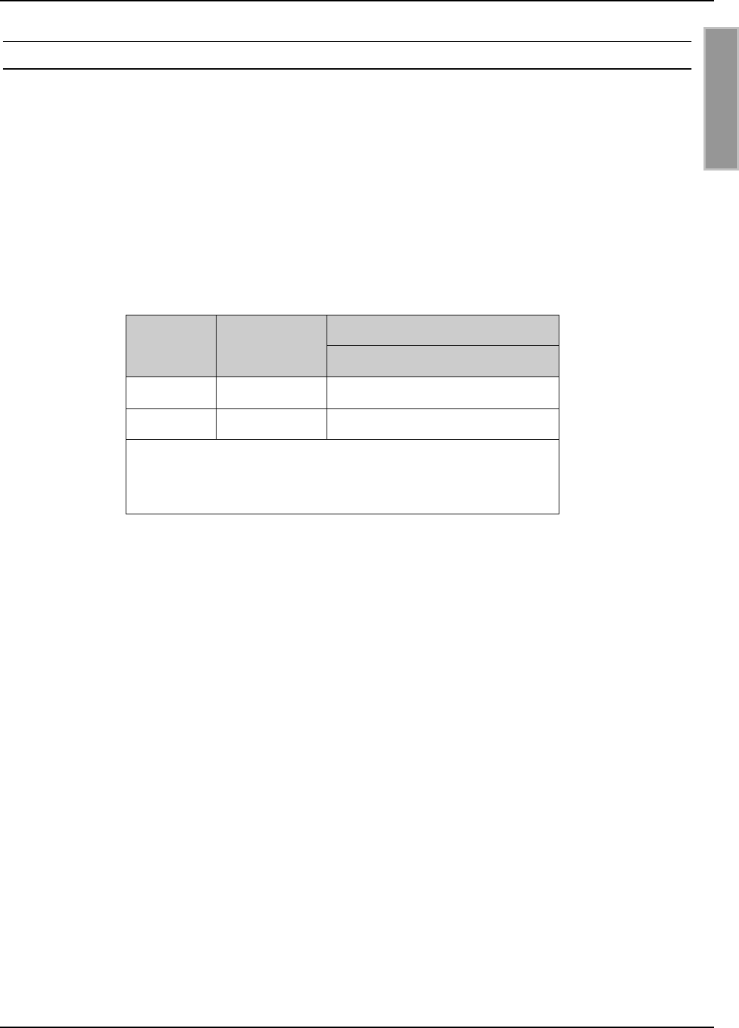
2.2. Verfügbare Modultypen
Folgende Modultypen sind z.Z. verfügbar:
Modultyp Beschreibung
ID ISC.M02-B Readermodul mit integrierter Antenne, RS232-C- und Daten-/Takt-
Schnittstelle, für eine Versorgungsspannung von 5 V DC
2.3. Lieferumfang
Folgende Komponenten sind im Lieferumfang enthalten:
Modultyp Lieferumfang
ID ISC.M02-B 1 x Readermodul ID ISC.M02-B
OBID® i-scan Montage ID ISC.M02
FEIG ELECTRONIC GmbH Seite 8 von 42 M20301-0de-ID-B.doc
D E U T S C H
3. Montage und Anschluss
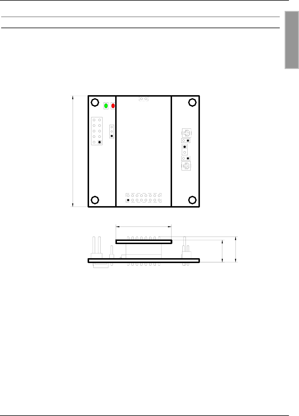
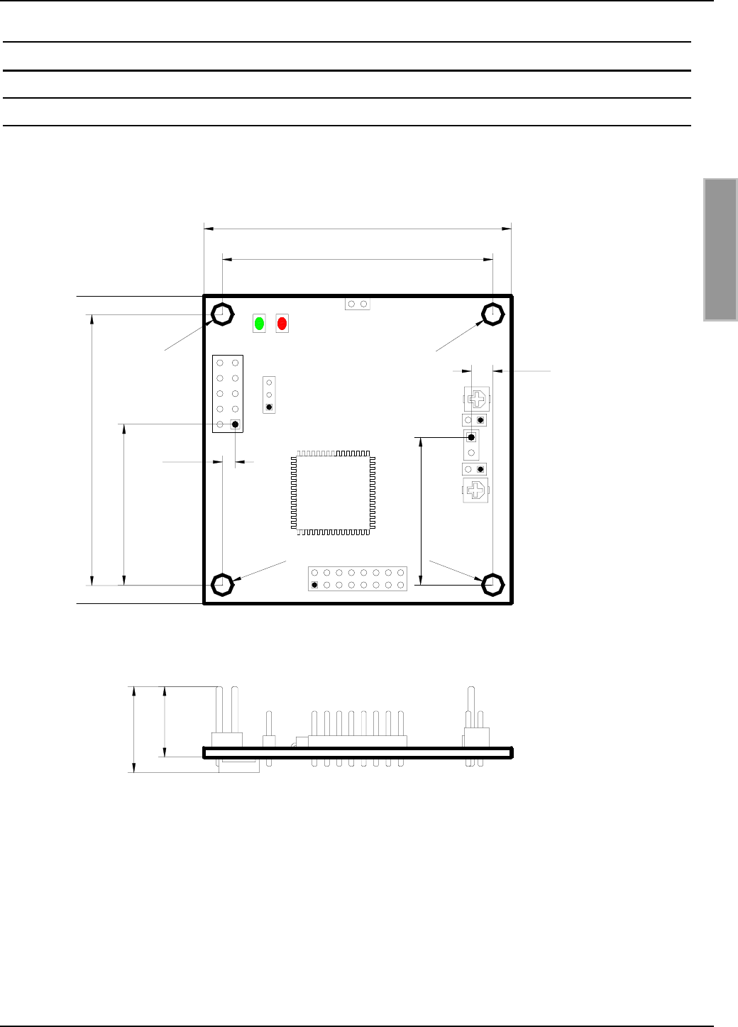
3.1. Abmessungen
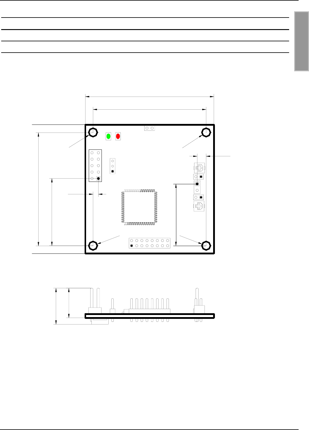
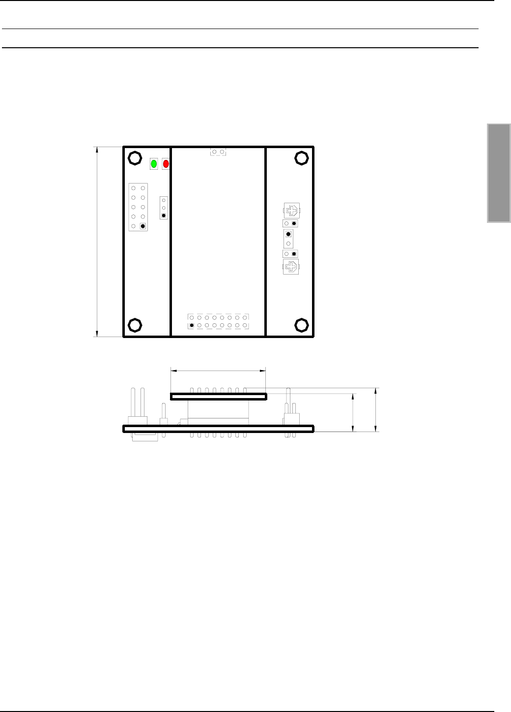
Bild 3.1-1 zeigt die Maßzeichnung des Readermoduls ID ISC.M02.
Bild 3.1-1: Maßzeichnung des Readermoduls ID ISC.M02
26,1
2,1
Ø3,3
Ø3,3
Ø3,3
Ø3,3
14,0
11,5
J2
J3
X2
X3
X4
44
,
0
24,0
3,5
X1
J1
V2V1
C65
44,0
50,0
C73
OBID® i-scan Montage ID ISC.M02
FEIG ELECTRONIC GmbH Seite 9 von 42 M20301-0de-ID-B.doc
D E U T S C H
3.2. Anschluss
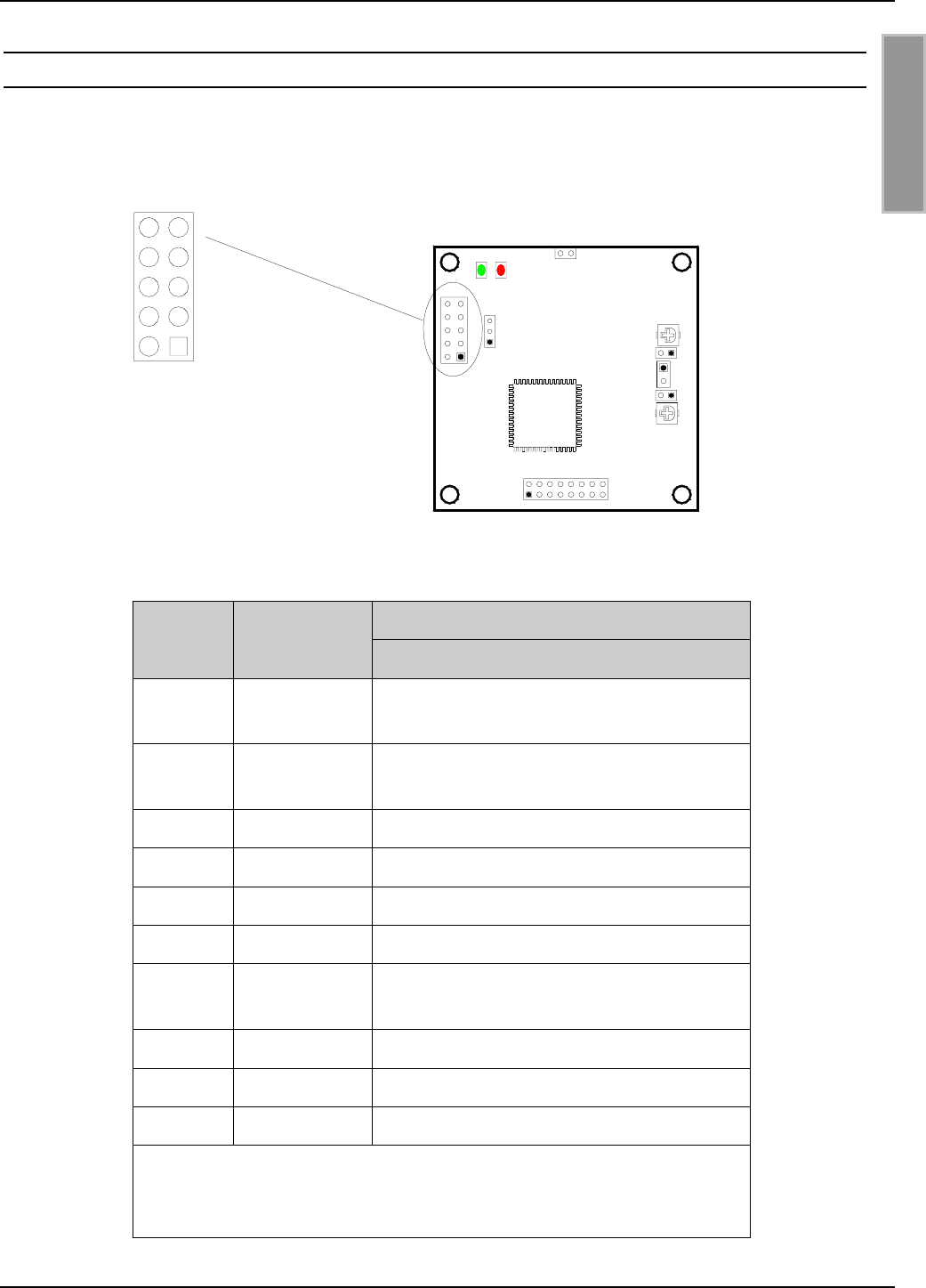
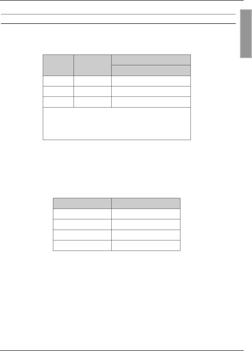
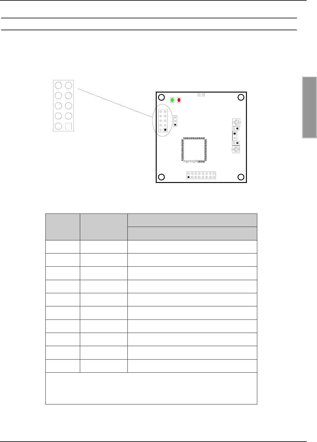
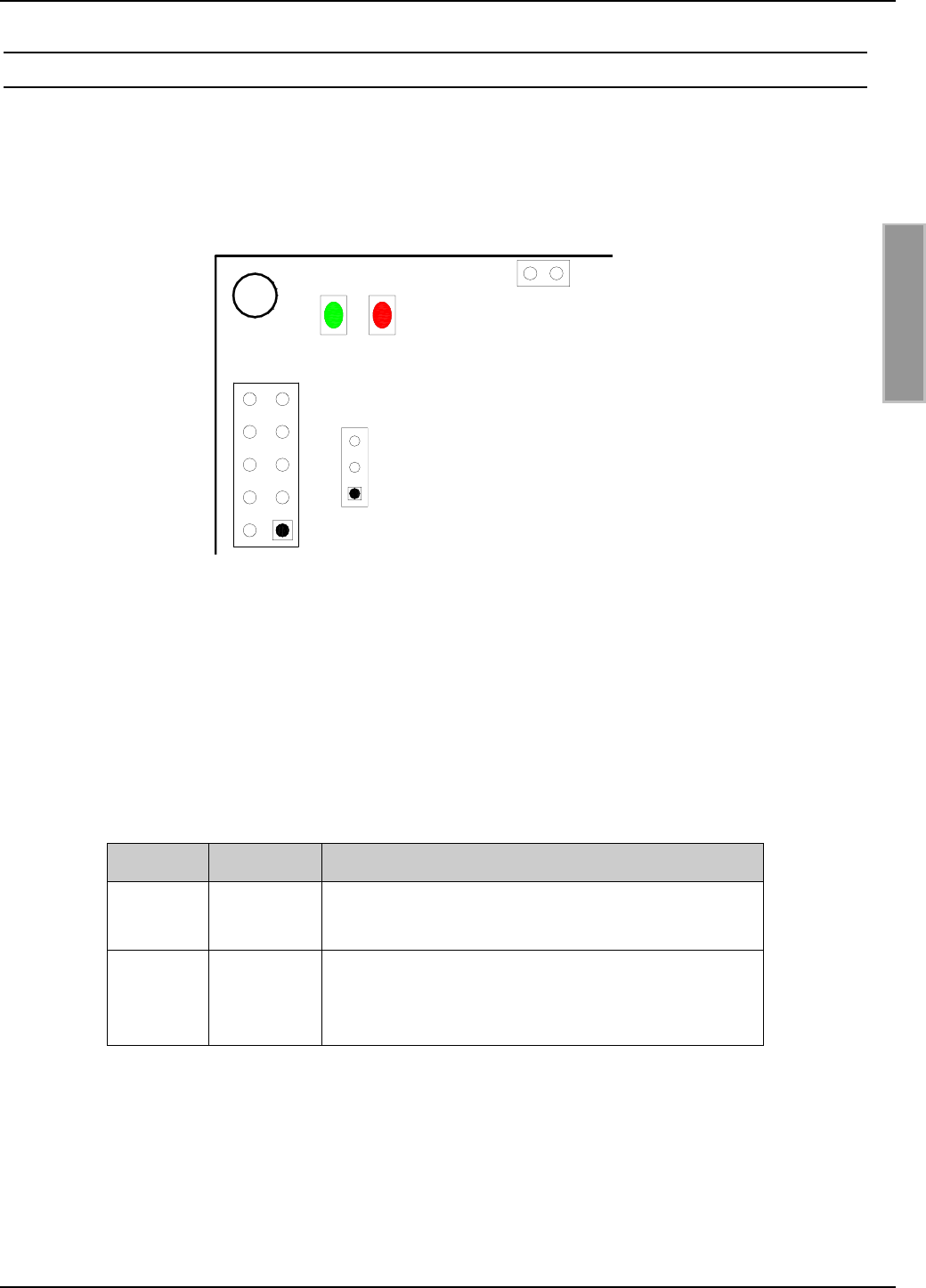
Bild 3.2-1 und Tabelle 3.2-1 zeigen die Belegung der Anschlussstiftleiste X1. Die Stiftleiste ist für
Flachbandkabelanschluss mittels IDC-Federleiste mit Rastermaß 2,54 mm ausgelegt.
Bild 3.2-1: Belegung der Anschlussstiftleiste X1
Beschreibung
X1
Pin-Nr. Kurzzeichen ID ISC.M02-B
1DAT Datenleitung der
Daten-/Taktschnittstelle
2CLK Taktleitung der
Daten-/Taktschnittstelle
3 TxD RS232-TTL – Transmit Data
4 GND ** GND
5 RxD RS232-TTL – Receive Data
6 --- Nicht angeschlossen
7CLS CLS-Leitung der
Daten-/Taktschnittstelle
8 VCC + 5 V DC *
9 GND ** GND
10 --- Nicht angeschlossen
* Nur geregelte DC-Spannungen verwenden !
** Die GND-Pins 4 und 9 sind auf dem Readermodul direkt
miteinander verbunden
Tabelle 3.2-1: Belegung der Anschlussstiftleiste X1
X1
J1
V2V1
C65
X1
12
43
5
7
9
6
8
10
J2
J3
X2
X3
X4
C73
OBID® i-scan Montage ID ISC.M02
FEIG ELECTRONIC GmbH Seite 10 von 42 M20301-0de-ID-B.doc
D E U T S C H
3.2.1. Spannungsversorgung
Für die Spannungsversorgung des ID ISC.M02-A/B dürfen nur geregelte DC-Spannungen ver-
wendet werden.
Im Falle von getakteten Netzteilen zur Versorgung des Moduls ist auf eine ausreichende Filterung
der Versorgungsspannung zu achten.
Störungen der Versorgungsspannung können sich in einer Reduzierung der Lese- und Schreib-
reichweite des Modules auswirken.
Die Länge des Zuleitungskabels der Spannungsversorgung sollte möglichst kurz sein. Sie darf 3 m
nicht überschreiten.
Beschreibung
X1
Pin-Nr. Kurzzeichen ID ISC.M02-B
8 VCC * + 5 V DC ± 5%
9, 4 GND ** GND
* Nur geregelte DC-Spannungen verwenden !
** Die GND-Pins 4 und 9 sind auf dem Readermodul
direkt miteinander verbunden
Tabelle 3.2.1-1: Pinbelegung der Spannungsversorgung an X1
HINWEIS:
• Eine Verpolung der Versorgungsspannung kann zur Zerstörung des Gerätes führen.
• Versorgungsspannungen außerhalb der Spezifikation können zur Zerstörung des Gerä-
tes führen.
OBID® i-scan Montage ID ISC.M02
FEIG ELECTRONIC GmbH Seite 11 von 42 M20301-0de-ID-B.doc
D E U T S C H
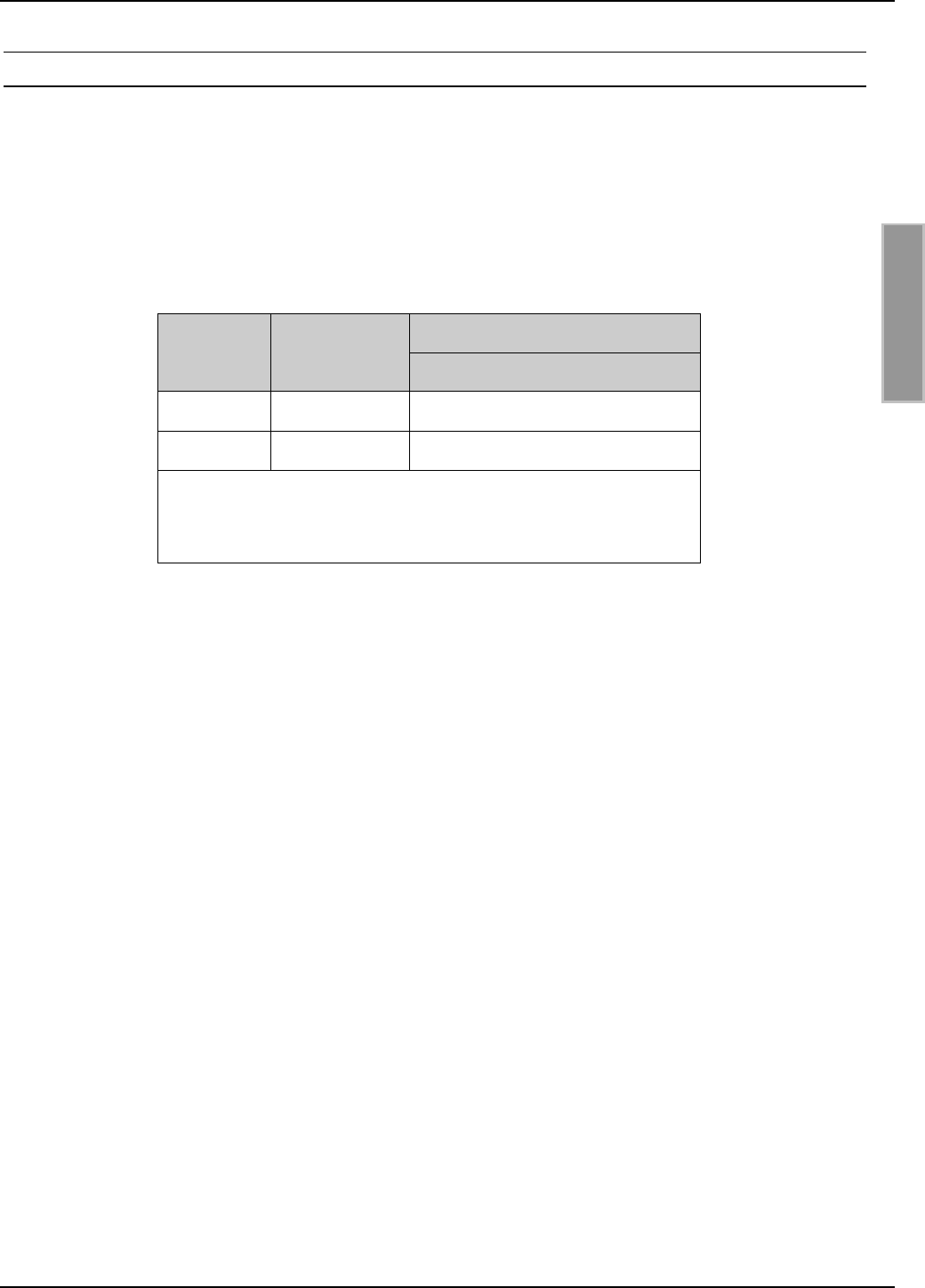
3.2.2. RS232-Schnittstelle
Die Länge des Zuleitungskabels der RS232-Schnittstelle sollte möglichst kurz sein. Sie darf 3 m
nicht überschreiten.
Beschreibung
X1
Pin-Nr. Kurzzeichen ID ISC.M02-B
3 TxD * RS232-TTL - Transmit Data
4, 9 GND ** GND
5 RxD * RS232-TTL - Receive Data
* Bezeichnungen der Signale aus Sichtweise des
Readermoduls.
** Die GND-Pins 4 und 9 sind auf dem Readermodul
direkt miteinander verbunden
Tabelle 3.2.2-1: Pinbelegung der RS232-Schnittstelle an X1
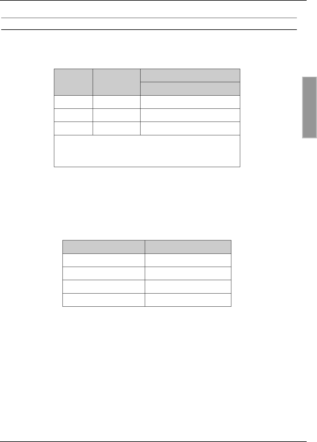
Die Übertragungsparameter der Schnittstelle können per Softwareprotokoll konfiguriert werden.
Tabelle 3.2.2-2 zeigt die Standardparameter der RS232-Schnittstelle.
Parameter Standardeinstellung
Baudrate 38400
Anzahl der Datenbits 8
Parität Even
Anzahl der Stoppbits 1
Tabelle 3.2.2-2: Standardparameter der RS232-Schnittstelle.
OBID® i-scan Montage ID ISC.M02
FEIG ELECTRONIC GmbH Seite 12 von 42 M20301-0de-ID-B.doc
D E U T S C H
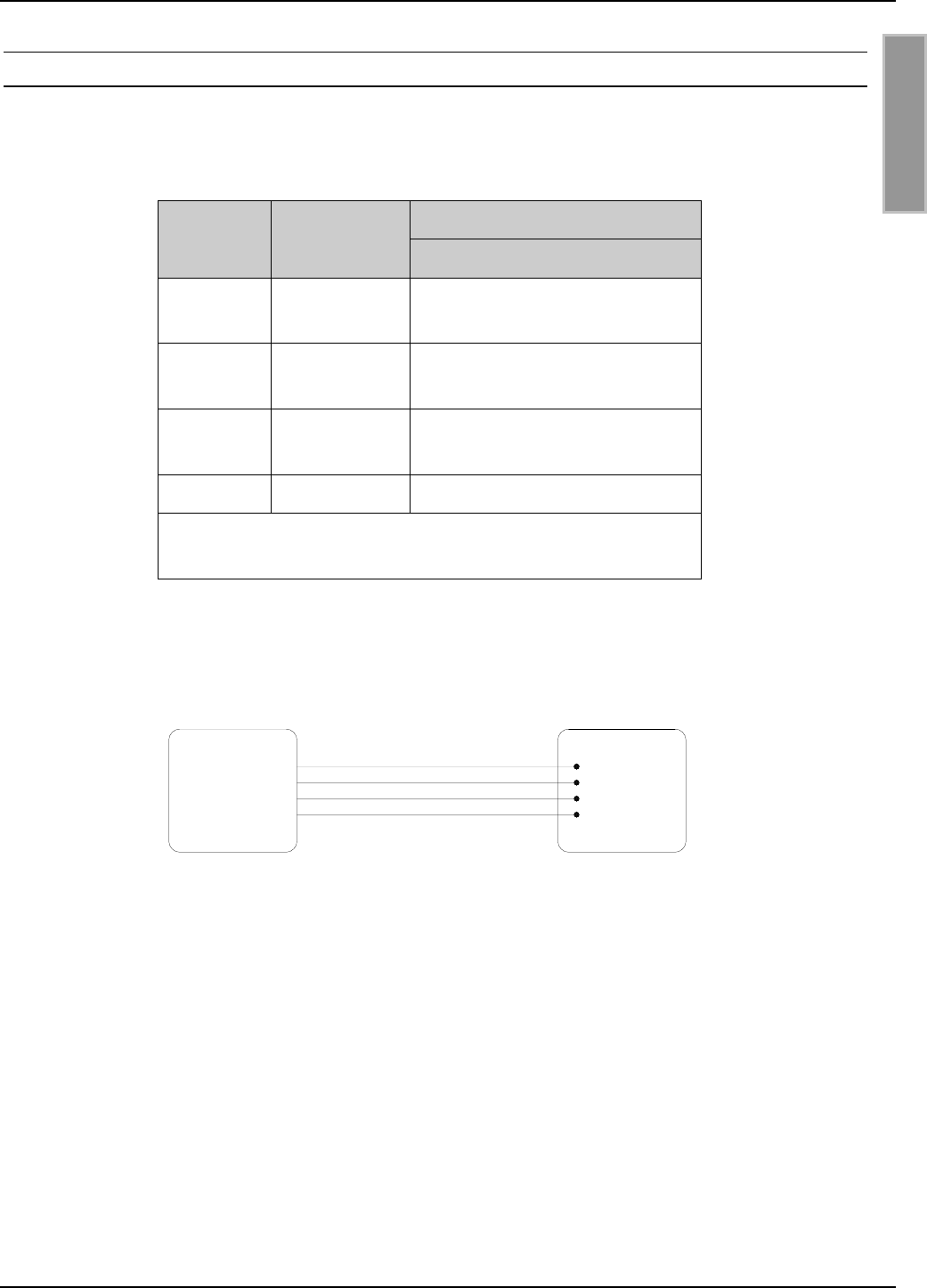
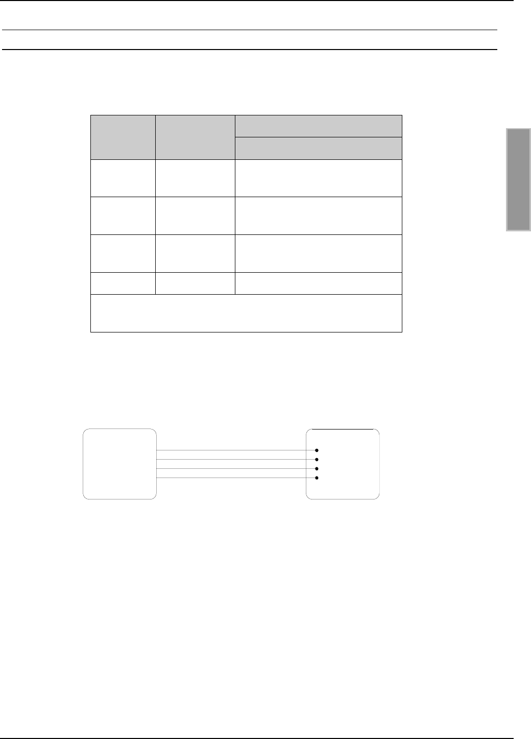
3.2.3. Daten-/Taktschnittstelle
Die Länge des Zuleitungskabels der Daten-/Taktschnittstelle sollte möglichst kurz sein. Sie darf
3 m nicht überschreiten.
Beschreibung
X1
Pin-Nr. Kurzzeichen ID ISC.M02-B
1DAT
Datenleitung der
Daten-/Taktschnittstelle
2CLK
Taktleitung der
Daten-/Taktschnittstelle
7CLS
CLS-Leitung der
Daten-/Taktschnittstelle
4, 9 GND * GND
* Die GND-Pins 4 und 9 sind auf dem Readermodul
direkt miteinander verbunden
Tabelle 3.2.3-1: Pinbelegung der RS232-Schnittstelle an X1
Bild 3.2.3-1: Anschluss der Daten-/Taktschnittstelle
Host
Data
Clock
CLS
GND
DAT
GND
CLK
CLS ID ISC.M02
OBID® i-scan Montage ID ISC.M02
FEIG ELECTRONIC GmbH Seite 13 von 42 M20301-0de-ID-B.doc
D E U T S C H
3.2.4. Optionales Security-Modul ID SAM.M02
Bei Bedarf kann optional auf die Stiftleisten X3 und X4 ein Security-Modul vom Typ ID SAM.M02
aufgesteckt werden.
Das Security-Modul ID SAM.M02 bietet zusätzliche Sicherheit durch kryptographische Datenüber-
tragung zwischen Reader und Transponder.
Bild 3.2.4-1: Maßzeichnung ID ISC.M02 mit ID SAM.M02
25,0
10,0
11,5
V2V1
50,0
X1
X2
X3
X4
OBID® i-scan Montage ID ISC.M02
FEIG ELECTRONIC GmbH Seite 14 von 42 M20301-0de-ID-B.doc
D E U T S C H
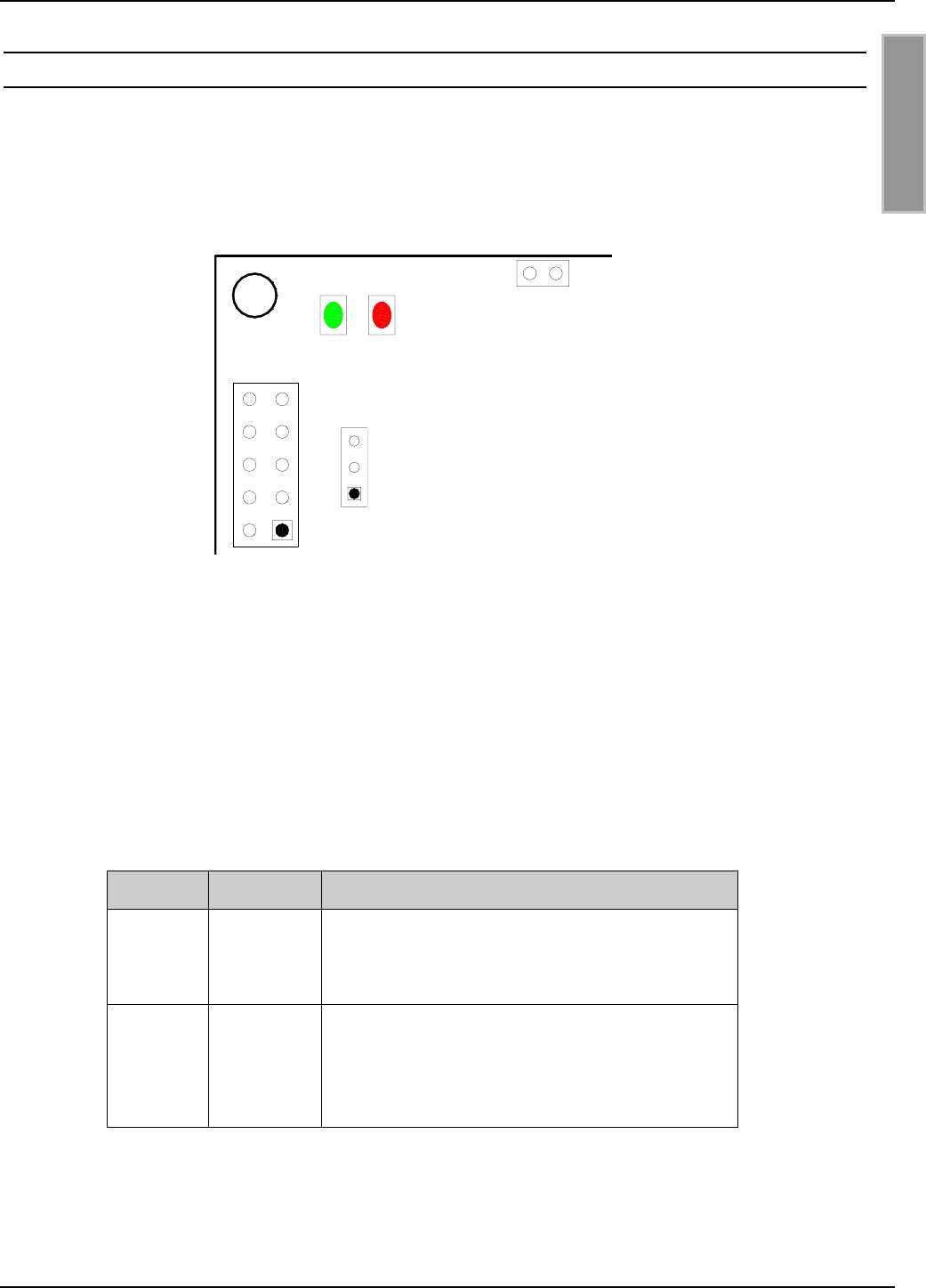
3.3. Anzeigeelemente
Das Readermodul ID ISC.M02 besitzt eine grüne LED (V1) und eine rote LED (V2) als Anzeige-
elemente (siehe Bild 3.3-1).
Bild 3.3-1: Position der LED´s V1 und V2
Die Funktionen der beiden LED´s können per Softwareprotokoll konfiguriert werden. Ergänzend
dazu besteht auch die Möglichkeit beide LED´s direkt durch ein weiteres Softwareprotokoll anzu-
steuern.
Tabelle 3.3-1 zeigt die Standardeinstellung von V1 und V2.
LED Farbe Standardeinstellung
V1 Grün
• Blinkt nach einem Reset vier mal.
• Blinkt kontinuierich mit einer Frequenz von
2 Hz.
V2 Rot
• Blinkt nach einem Reset vier mal.
• Leuchtet nach einer erfolgreichen
Kommunikation mit einem Transponder für
1 Sekunde.
Tabelle 3.3-1: Standardeinstellung der LED´s
X1
J1
V2
V1 X4
OBID® i-scan Montage ID ISC.M02
FEIG ELECTRONIC GmbH Seite 15 von 42 M20301-0de-ID-B.doc
D E U T S C H
3.4. Bedienelemente
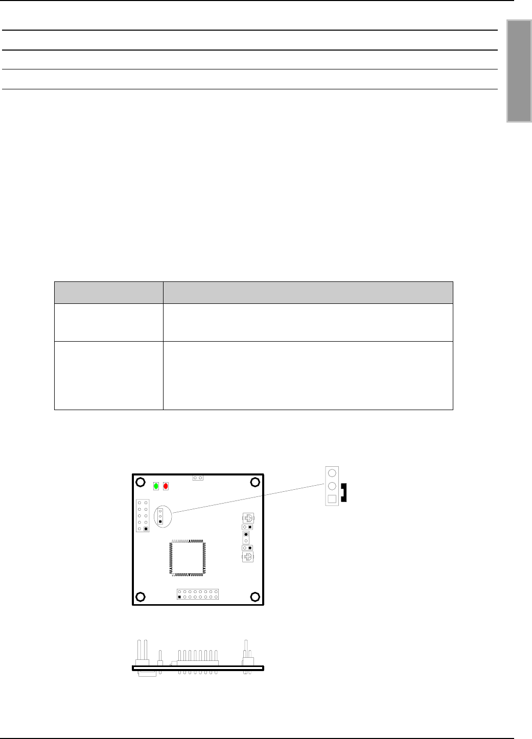
3.4.1. Betriebs-/Programmier-Mode: Jumper J1
Der Jumper J1 dient zur Konfiguration des Betriebs- bzw. Programmier-Mode des ID ISC.M02.
Im Standardbetrieb ist der Jumper auf die Position 1-2 gesteckt (siehe Bild 3.4.1-1). Der Reader
befindet sich dann im normalen Betriebsmode.
Wird der Jumper auf die Position 2-3 gesteckt, so startet nach einem Reset der integrierte
Hardware Bootloader. Da die Firmware des Readers jedoch auch über einen Software Bootloader
verfügt, sollte die Option des Hardware Bootloaders nur für die Installation des Software Boot-
loaders gewählt werden.
Näheres zum Programmieren des Readers kann in der entsprechenden Application Note
"Firmware Update" nachgelesen werden.
Jumperposition Mode
1 - 2 Standardeinstellung :
Der Reader befindet sich im normalen Betriebsmode.
2 - 3
Aktivierung des Hardware-Bootloaders :
Nach einem Reset startet die CPU des Readers
seinen Hardware Bootloader und kann über diesen
neu programmiert werden.
Tabelle 3.4.1-1: Jumper J1
Bild 3.4.1-1: Jumper J1
J1
1
2
3
J2
J3
X2
X3
X4 Standard-
einstellung
X1
J1
V2V1
C65
C73
OBID® i-scan Montage ID ISC.M02
FEIG ELECTRONIC GmbH Seite 16 von 42 M20301-0de-ID-B.doc
D E U T S C H
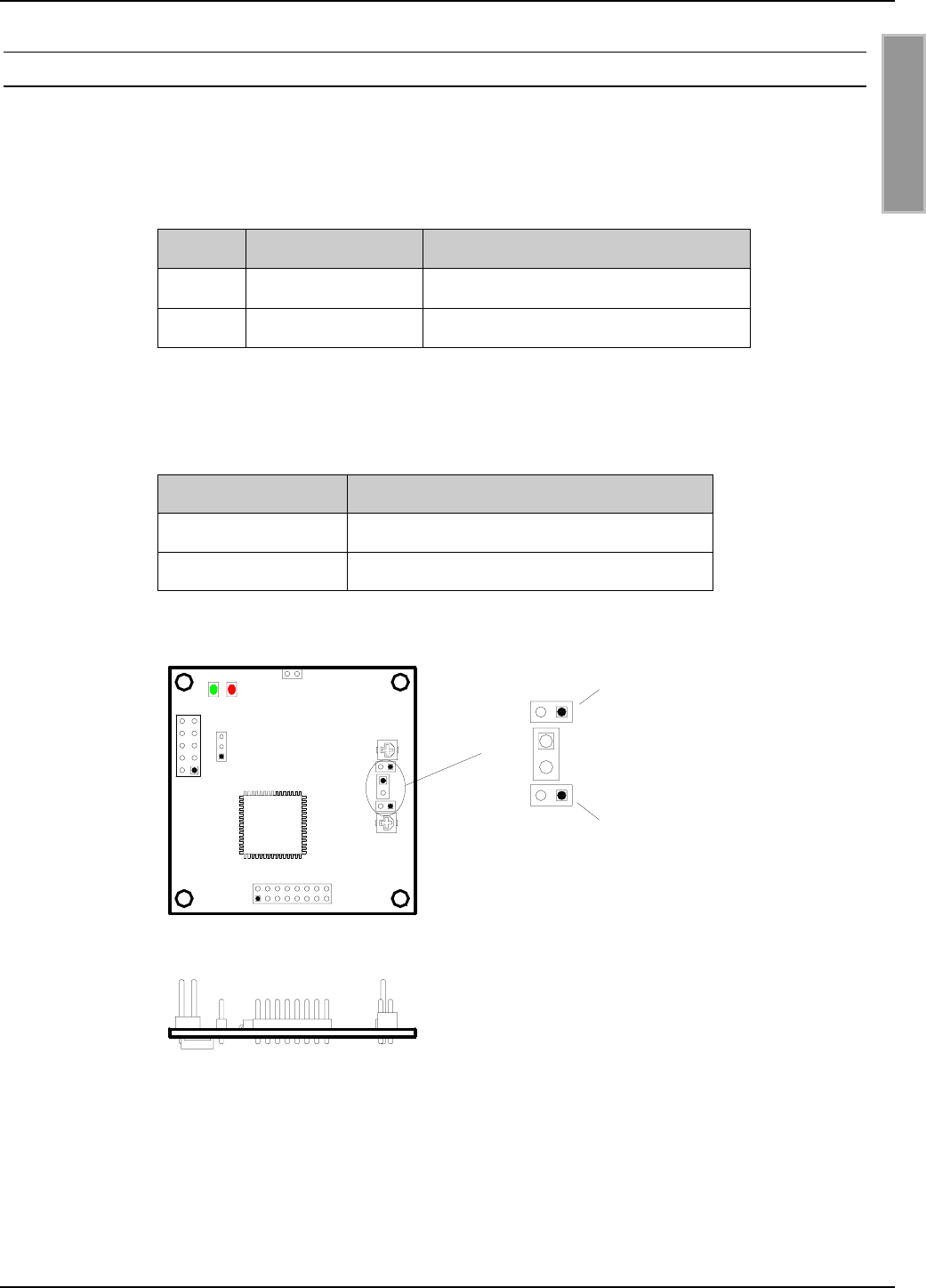
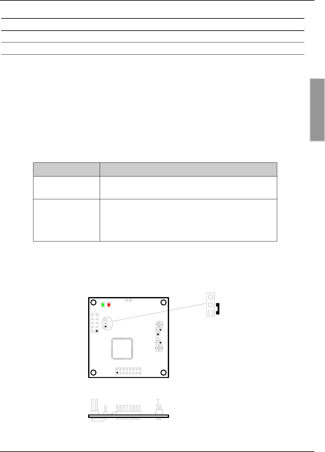
3.4.2. Interne/Externe Antenne: Stiftleiste X2, Jumper J2 und J3
Die Stiftleiste X2 dient zum Anschluss einer externen 50Ω-Antenne an den ID ISC.M02. Hierbei
handelt es sich um eine Standardstiftleiste mit dem Rastermaß 2,54 mm. Tabelle 3.4.2-1 zeigt die
Anschlussbelegung der Stiftleiste X2.
Pin-Nr. Kurzzeichen Beschreibung
1 Signal 50Ω-Signalausgang
2 GND GND-Anschluss
Tabelle 3.4.2-1: Anschlussbelegung der Stiftleiste X2
Die Jumper J2 und J3 verbinden die interne Antenne mit der Treiberschaltung des Readers. Für
den Anschluss einer externen Antenne müssen die beiden Jumper J2 und J3 daher geöffnet
werden.
Jumper J2 und J3 Beschreibung
geschlossen Anschluss der internen Antenne
offen Anschluss einer externen Antenne
Tabelle 3.4.2-2: Konfiguration der Jumper J2 und J3
Bild 3.4.2-1: Anschluss und Konfiguration interne/externe Antenne
HINWEIS:
• Werden die beiden Jumper J2 und J3 nach dem Anschluss einer externen Antenne nicht
geöffnet, so wird der Sender des Readers durch beide Antennen belastet. Dies kann zu
dessen Zerstörung führen!
J2
J3
X2
X3
X4
J2
X2
J3
Signal
GND }Anschluß
ext. Antenne
Geschlossen: int. Antenne
Offen: ext. Antenne
Geschlossen: int. Antenne
Offen: ext. Antenne
1
2
X1
J1
V2
V1
C65
C73
OBID® i-scan Montage ID ISC.M02
FEIG ELECTRONIC GmbH Seite 17 von 42 M20301-0de-ID-B.doc
D E U T S C H
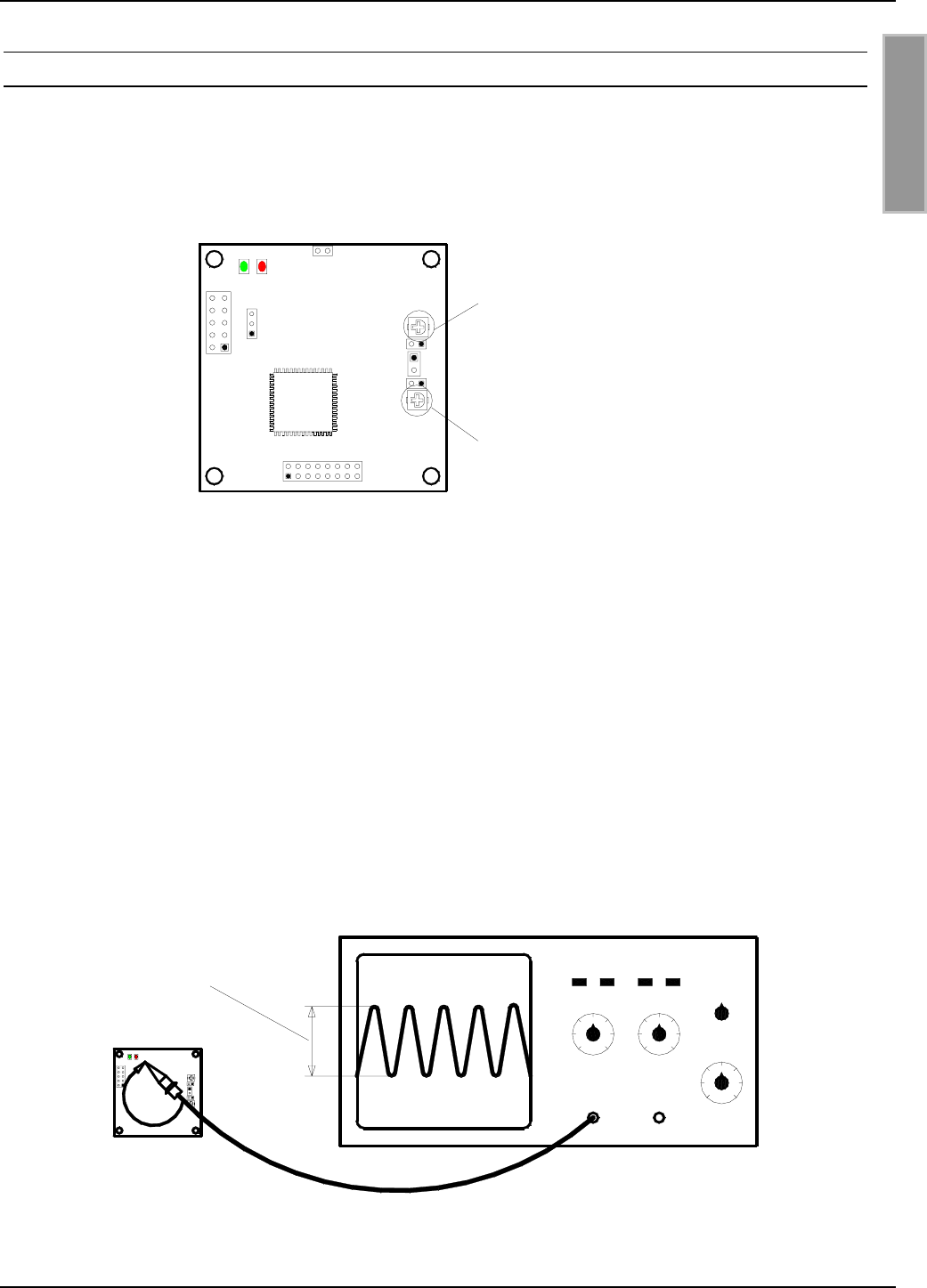
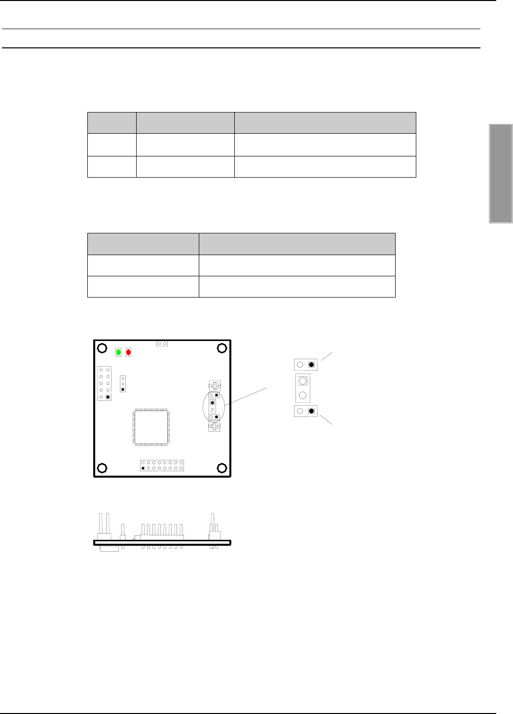
3.4.3. Nachgleich der internen Antenne: Trimmkondensator C65
Die Antenne des ID ISC.M02 kann durch verschiedene Umgebungseinflüsse wie zum Beispiel
Metalle verstimmt werden (siehe Kapitel 3.5). Diese Verstimmungen können in einem gewissen
Rahmen durch den Trimmkondensator C65 ausgeglichen werden.
Bild 3.4.3-1: Trimmkondensator zum Nachgleich der Antenne
Der Nachgleich der integrierten Antenne kann mit Hilfe eines Oszilloskopes (Bandbreite ≥ 20 MHz)
durchgeführt werden. Dazu wird der GND-Anschluss des Oszilloskoptastkopfes mit der Tastkopf-
spitze kurzgeschlossen und anschließend über die Leiterplatte des ID ISC.M02 gehalten. Der
Tastkopf bildet so eine Meßschleife für das abgestrahlte magnetische Feld des ID ISC.M02. Der
Abstand zwischen Oszilloskoptastkopf und ID ISC.M02 sollte im Bereich 0 bis 3 cm liegen.
Nun muss mit Hilfe des Software-Kommandos "RF-ON" (0x6A) das HF-Feld des ID ISC.M02
eingeschaltet werden. Auf dem Bildschirm des Oszilloskopes sollte anschließend ein 13,56 MHz-
Signal zu sehen sein.
Für den Abgleich der internen Antenne muss nun die Signalamplitude des 13,56 MHz-Signals mit
Hilfe des Trimmkondensators C65 auf Maximum abgeglichen werden.
Bild 3.4.3-2: Messaufbau zum Abgleich der internen Antenne
ID ISC.M02
Mit C65 Signalamplitude auf
Maximum drehen
V1 V2
X1
C65
C73
Trimmkondensator C65:
Nachgleich der
internen Antenne
Trimmkondensator C73:
NICHT VERÄNDERN !!!
J2
J3
X2
X3
X4
X1
J1
V2V1
C65

OBID® i-scan Montage ID ISC.M02
FEIG ELECTRONIC GmbH Seite 18 von 42 M20301-0de-ID-B.doc
D E U T S C H
Wird der maximale Wert der Signalamplitude bei der Minimum- oder Maximumposition des Trimm-
kondensators erreicht (Bild 3.4.3-3), so ist Vorsicht geboten. In diesem Fall ist meist die Verstim-
mung der Antenne durch die Umgebung zu groß und kann durch den Trimmkondensator nicht
vollständig ausgeglichen werden.
Beschriftung
Minimale
Kapazität
Maximale
Kapazität
Bild 3.4.3-3: Minimal- und Maximalposition des Trimmkondensators C65
Im Anschluss an den Abgleichvorgang sollte die Antenne noch einmal auf ihre maximale Reich-
weite und eventuelle Kommunikationslöcher untersucht werden.
HINWEIS:
• Trotz der hier beschriebenen Möglichkeit des Antennennachgleichs sollte der Abstand
zwischen Reader und den umgebenden Metallflächen mindestens 3 cm betragen. Dabei
sollte bedacht werden, dass sich auch andere Leiterplatten, je nach Kupferauflage, wie
Metallflächen verhalten.

OBID® i-scan Montage ID ISC.M02
FEIG ELECTRONIC GmbH Seite 19 von 42 M20301-0de-ID-B.doc
D E U T S C H
3.5. Montagehinweise
Folgende mögliche Beeinflussungen durch die Umgebung sollten beim Einbau eines ID ISC.M02
in ein anderes Gerät beachtet werden :
• Beeinflussung durch eine metallische Umgebung
⇒ Verstimmung der integrierten Antenne
⇒ Beeinträchtigung der Ausbreitung des magnetischen Feldes der Antenne
• EMV-Beeinflussung über Zuleitungen
⇒ Beeinträchtigung der Kommunikation zwischen Reader und Label
• EMV-Beeinflussungen über magnetische Felder
⇒ Beeinträchtigung der Kommunikation zwischen Reader und Label
3.5.1. Metallische Umgebung
Beim Einbau eines ID ISC.M02 in ein anderes Gerät ist darauf zu achten, dass sich möglichst kei-
ne Metallflächen bzw. Metallteile in der direkten Umgebung des Readers befinden. Diese können
die Antenne verstimmen und so das magnetische Feld der integrierten Antenne reduzieren. Dies
wirkt sich dann in einer reduzierten Lesereichweite des Readers aus.
Der Abstand zwischen Reader und Metallfläche sollte mindestens 3 cm betragen. Dabei
sollte bedacht werden, dass sich auch andere Leiterplatten, je nach Kupferauflage, wie Me-
tallflächen verhalten.
Ist eine metallische Umgebung nicht zu vermeiden, so sollten die Abstände im Interesse der sta-
bilen Funktion jedoch so groß wie nur irgend möglich gewählt werden.
Auch der Bereich zwischen Antenne und Label, sowie der Bereich auf der anderen Seite des Label
sollte frei von Metallteilen sein.
Da jede Veränderung der metallischen Umgebung zu einer Verstimmung der integrierten Antenne
und dadurch einer Beeinträchtigung der Funktion führt, sollten sich keine beweglichen Metallteile,
wie z.B. metallische Lüfter, in der Nähe des Readers befinden.
3.5.2. EMV-Beeinflussung über Zuleitungen
Trotz der internen EMV-Filter des Readers kann es durch starke Störungen auf der Spannungs-
versorgung zu Beeinträchtigungen der Kommunikation zwischen Reader und Transponder kom-
men.
Beim Einbau eines ID ISC.M02 in ein anderes Gerät sollte daher auf eine möglichst saubere, stör-
freie Spannungsversorgung geachtet werden.

OBID® i-scan Montage ID ISC.M02
FEIG ELECTRONIC GmbH Seite 20 von 42 M20301-0de-ID-B.doc
D E U T S C H
3.5.3. EMV-Beeinflussung über magnetische Felder
Da im vorliegenden Fall der RF-ID-Technik die Kommunikation zwischen Reader und Transponder
mittels der Modulation eines magnetischen Feldes abläuft, können sich magnetische Wechselfel-
der in der Nähe der Antenne negativ auf dessen Funktion auswirken.
Zu den Quellen solcher magnetischen Störfelder gehören zum Beispiel Spulen innerhalb eines
primär oder sekundär getakteten Netzteils.
Bei der Festlegung der Position von Reader und Antenne in einem Gerät sollte dieses auf eventu-
elle Störquellen in der oben angegebenen Form untersucht werden. Notfalls sind Abschirmmaß-
nahmen zur Unterdrückung einer solchen Störquelle anzuwenden.

OBID® i-scan Montage ID ISC.M02
FEIG ELECTRONIC GmbH Seite 21 von 42 M20301-0de-ID-B.doc
D E U T S C H
4. Funkzulassungen
4.1. Europa (CE)
Die Funkanlage entspricht, bei bestimmungsgemäßer Verwendung den grundlegenden Anforde-
rungen des Artikels 3 und den übrigen einschlägigen Bestimmungen der R&TTE Richtlinie
1999/5/E6 vom März 99.
4.2. USA (FCC)
FCC ID: PJMISCM02
This device complies with Part 15 of the FCC Rules. Operation is subject to the following
two conditions:
(1) this device may not cause harmful interference, and
(2) this device must accept any interference received, including interference that may
cause undesired operation.
Unauthorized modifications may void the authority granted under Federal communica-
tions Commission Rules permitting the operation of this device.
This device is labeled with an FCC ID number.
If this label is not visible when installed in an end device, the outside of the device MUST
also display a label referring to the enclosed module.
Wording on the label similar to the following shall be used:
This device contains transmitter module FCC ID PJMISCM02
At the time of this printing, the antennas listed below were the only antennas approved for
use with the ID ISC.M02 module. Use of other antennas must be approved by
FEIG ELECTRONIC GmbH.
Antennas approved: ID ISC.ANT100100; ID ISC.ANT4030

OBID® i-scan Montage ID ISC.M02
FEIG ELECTRONIC GmbH Seite 22 von 42 M20301-0de-ID-B.doc
D E U T S C H
5. Technische Daten
Mechanische Daten
• Abmessungen ( B x H x T ) 50mm x 50mm x 14 mm
• Anschlussstecker 10 polige Stiftleiste mit Rastermaß 2,54mm
Elektrische Daten
• Spannungsversorgung
Version –B 5 V DC ± 5%
• Leistungsaufnahme max. 1 W
• Betriebsfrequenz 13.56 MHz
• Sendeleistung 90 mW ± 2 dB
• Antenne Interne Antenne, 48mm x 48mm;
Anschluß einer externen 50Ω-Antenne möglich
• Schnittstellen
Version –B RS232 - TTL-Level, Daten-/Taktschnittstelle
Funktionelle Eigenschaften
• EEPROM (für Parameter) 1 kB
(10,000 Schreibzyklen)
• FLASH 64 kB
(Softwareupdate über Schnittstelle möglich)
• Unterstützte Transponder • ISO15693 (I•Code SLI, Tag-It HFI, my-d vicinity,
STM LRI512), I•Code 1
• Optional:
SAM (Security Access Module),
z.B. für my-d vicinity
• Optische Anzeigen 2 LED´s
Umgebungsbedingungen
• Temperaturbereich
– Betrieb
– Lagerung
-20°C bis +70°C
-40°C bis +85°C
Angewendete Normen
• Zulassung Funk
– Europa
– USA
EN 300 330
FCC 47 CFR Part 15
• EMV EN 301 489
• Sicherheit EN 60950

OBID® i-scan Montage ID ISC.M02
FEIG ELECTRONIC GmbH Seite 23 von 42 M20301-0de-ID-B.doc
D E U T S C H

OBID®Installation ID ISC.M02
FEIG ELECTRONIC GmbH Page 24 of 42 M20301-0de-ID-B.doc
E N G L I S H
Note
Copyright 2002 by
FEIG ELECTRONIC GmbH
Lange Strasse 4
D-35781 Weilburg-Waldhausen
Tel.: +49 6471 3109-0
http://www.feig.de
Edition: er/03/02/11 - m20301-0de-id-b.doc
With the edition of this manual, all previous editions become void. Indications made in this manual may be
changed without previous notice.
Copying of this document, and giving it to others and the use or communication of the contents thereof are
forbidden without express authority. Offenders are liable to the payment of damages. All rights are reserved
in the event of the grant of a patent or the registration of a utility model or design.
Composition of the information in this manual has been done to the best of our knowledge. FEIG
ELECTRONIC GmbH does not guarantee the correctness and completeness of the details given in this
manual and may not be held liable for damages ensuing from incorrect or incomplete information. Since,
despite all our efforts, errors may not be completely avoided, we are always grateful for your useful tips.
The installation instructions given in this manual are based on advantageous boundary conditions. FEIG
ELECTRONIC GmbH does not give any guarantee promise for perfect function in cross environments.
FEIG ELECTRONIC GmbH assumes no responsibility for the use of any information contained in this
manual and makes no representation that they free of patent infringement. FEIG ELECTRONIC GmbH does
not convey any license under its patent rights nor the rights of others.
OBID® is registered trademark of FEIG ELECTRONIC GmbH.

OBID®Installation ID ISC.M02
FEIG ELECTRONIC GmbH Page 25 of 42 M20301-0de-ID-B.doc
E N G L I S H
Contents
6. Safety Instructions / Warning - Read before start-up ! 26
7. Performance Characteristics of the ID ISC.M02 Reader Module 27
7.1. Performance Characteristics......................................................................................... 27
7.2. Available module types.................................................................................................. 27
7.3. Scope of delivery............................................................................................................ 27
8. Installation and wiring 28
8.1. Dimensions..................................................................................................................... 28
8.2. Wiring.............................................................................................................................. 29
8.2.1. Supply voltage ..........................................................................................................30
8.2.2. RS232 interface ........................................................................................................ 31
8.2.3. Data/Clock interface.................................................................................................. 32
8.2.4. Optional Security Module ID SAM.M02 ..................................................................... 33
8.3. Display elements ............................................................................................................ 34
8.4. Operating elements ........................................................................................................35
8.4.1. Operating/Programming Mode: Jumper J1................................................................ 35
8.4.2. Internal/External antenna: Terminal X2, Jumpers J2 and J3 ..................................... 36
8.4.3. Retuning the internal antenna: Trim capacitor C65 ................................................... 37
8.5. Installation notes............................................................................................................ 39
8.5.1. Metallic surroundings ................................................................................................ 39
8.5.2. EMC effects on cables .............................................................................................. 39
8.5.3. EMC effects from magnetic fields.............................................................................. 40
9. Radio Approvals 41
9.1. Europe (CE)..................................................................................................................... 41
9.2. USA (FCC) ....................................................................................................................... 41
10. Technical Data 42

OBID®Installation ID ISC.M02
FEIG ELECTRONIC GmbH Page 26 of 42 M20301-0de-ID-B.doc
E N G L I S H
6. Safety Instructions / Warning - Read before start-up !
• The device has to be used only for the purpose designed by the manufacturer.
• The operation manual has to be stored available at any time and has to be handed over to
each user.
• Unauthorized changes and the use of spare parts and additional devices which have not been
sold or recommended by the manufacturer may cause fire, electric shocks or injuries. Such
measures will lead to exclusion of any liability by the manufacturer.
• The liability-prescriptions of the manufacturer in the issue valid at the time of purchase are valid
for the device. The manufacturer is not legally responsible for incorrect, unsuitable manual or
automatical setting of parameters for a device or the incorrect application of a device.
• Repairs can only be executed by the manufacturer.
• Installation-, operation- and maintenance procedures should only be carried out by qualified
personnel.
• Before opening the device, the power supply must always be interrupted. Make sure that the
device is without voltage by measuring. CAUTION! The fading of an operation control (LED) is
no indicator for an interrupted power supply or the device being without voltage!
• Works at the device and its installation have to be executed according to the national legal
requirements and local prescriptions.
• When working on devices the valid safety regulations must be observed.

OBID®Installation ID ISC.M02
FEIG ELECTRONIC GmbH Page 27 of 42 M20301-0de-ID-B.doc
E N G L I S H
7. Performance Characteristics of the ID ISC.M02 Reader Module
7.1. Performance Characteristics
The ID ISC.M02 Reader Module is designed for reading and writing passive transponders, so-
called “Smart Labels”, with an operating frequency of 13.56 MHz. It is suitable for any application in
which short read ranges and small reader dimensions are required.
The module has an integrated antenna which eliminates the need for additional external antenna
components.
Depending on the requirements, an external 50Ω antenna may also be optionally connected.
7.2. Available module types
The following module types are currently available:
Module type Description
ID ISC.M02-B Reader Module with integrated antenna, RS232-C and data/clock in-
terface, for a supply voltage of 5 V DC
7.3. Scope of delivery
The following components are included:
Module type Included
ID ISC.M02-B 1 x Reader Module ID ISC.M02-B
OBID®Installation ID ISC.M02
FEIG ELECTRONIC GmbH Page 28 of 42 M20301-0de-ID-B.doc
E N G L I S H
8. Installation and wiring
8.1. Dimensions
Fig. 3.1-1 shows the dimensions of the ID ISC.M02 Reader Module
Fig. 3.1-1: Dimensions of the ID ISC.M02 Reader Module
26,1
2,1
Ø3,3
Ø3,3
Ø3,3
Ø3,3
14,0
11,5
J2
J3
X2
X3
X4
44
,
0
24,0
3,5
X1
J1
V2V1
C65
44,0
50,0
C73
OBID®Installation ID ISC.M02
FEIG ELECTRONIC GmbH Page 29 of 42 M20301-0de-ID-B.doc
E N G L I S H
8.2. Wiring
Fig. 3.2-1 and Table 3.2-1 show the pin assignments for Terminal X1. The pin connector is de-
signed for flat cable connection using an IDC multipoint socket connector with 2.54 mm pin spac-
ing.
Fig. 3.2-1: Pin assignments for Terminal X1
Description
X1
Pin no. Function ID ISC.M02-B
1 DAT Data line for the data/clock interface
2 CLK Clock line for the data/clock interface
3 TxD RS232-TTL – Transmit Data
4 GND ** GND
5 RxD RS232-TTL – Receive Data
6 --- not connected
7 CLS CLS line for the data/clock interface
8 VCC + 5 V DC *
9 GND ** GND
10 --- not connected
* Use only regulated DC power supplies !
** GND-Pins 4 and 9 are to be connected directly to each other
on the Reader Module
Table 3.2-1: Pin assignments for Terminal X1
X1
J1
V2V1
C65
X1
12
43
5
7
9
6
8
10
J2
J3
X2
X3
X4
C73
OBID®Installation ID ISC.M02
FEIG ELECTRONIC GmbH Page 30 of 42 M20301-0de-ID-B.doc
E N G L I S H
8.2.1. Supply voltage
The ID ISC.M02-A/B must be supplied only by a regulated power supply.
If switching power supplies are used with the module, be sure that there is adequate filtering.
Noise from the power supply can result in a reduction of the read/write range of the module.
The cable length from the power supply should be as short as possible, and should in any case not
exceed 3 m.
Description
X1
Pin no. Function ID ISC.M02-B
8 VCC * + 5 V DC ± 5%
9, 4 GND ** GND
* Use only regulated power supplies !
** GND-Pins 4 and 9 are to be connected directly to each
other on the Reader Module
Table 3.2.1-1: Pin assignments for X1
NOTE:
• Reversing the polarity of the supply voltage may destroy the device.
• Supply voltages outside the specifications may destroy the device.
OBID®Installation ID ISC.M02
FEIG ELECTRONIC GmbH Page 31 of 42 M20301-0de-ID-B.doc
E N G L I S H
8.2.2. RS232 interface
The length of the cable to the RS232 interface should be kept as short as possible, and must in
any case not exceed 3 m.
Description
X1
Pin no. Function ID ISC.M02-B
3 TxD * RS232-TTL - Transmit Data
4, 9 GND ** GND
5 RxD * RS232-TTL - Receive Data
* Signal names as seen by the Reader Module.
** GND-Pins 4 and 9 are to be connected directly to each
other on the Reader Module
Table 3.2.2-1: Pin assignments for the RS232 interface on X1
The transmission parameters for the interface can be software-configured. Table 3.2.2-2 shows the
standard parameters for the RS232 interface.
Parameter Standard setting
Baud rate 38400
No. of data bits 8
Parity Even
No. of stop bits 1
Table 3.2.2-2: Standard parameters of the RS232 interface.
OBID®Installation ID ISC.M02
FEIG ELECTRONIC GmbH Page 32 of 42 M20301-0de-ID-B.doc
E N G L I S H
8.2.3. Data/Clock interface
The length of the cable to the data/clock interface should be kept as short as possible. It must not
exceed 3 m.
Description
X1
Pin no. Function ID ISC.M02-B
1DAT
Data line for the data/clock in-
terface
2CLK
Clock line for the data/clock
interface
7CLS
CLS line for the data/clock in-
terface
4, 9 GND * GND
* GND-Pins 4 and 9 are to be connected directly to each
other on the Reader Module
Table 3.2.3-1: Pin configuration for the RS232 interface on Terminal X1
Fig. 3.2.3-1: Connecting the data/clock-interface
Host
Data
Clock
CLS
GND
DAT
GND
CLK
CLS ID ISC.M02
OBID®Installation ID ISC.M02
FEIG ELECTRONIC GmbH Page 33 of 42 M20301-0de-ID-B.doc
E N G L I S H
8.2.4. Optional Security Module ID SAM.M02
If needed, the optional ID SAM.M02 Security Module can be connected to terminals X3 and X4.
The ID SAM.M02 Security Module provided additional security by using cryptographic data trans-
mission between the reader and transponder.
Fig. 3.2.4-1: Dimensions of ID ISC.M02 with ID SAM.M02
25,0
10,0
11,5
V2V1
50,0
X1
X2
X3
X4
OBID®Installation ID ISC.M02
FEIG ELECTRONIC GmbH Page 34 of 42 M20301-0de-ID-B.doc
E N G L I S H
8.3. Display elements
The ID ISC.M02 Reader Module has a green LED (V1) and a red LED (V2) which are used as dis-
play elements (Fig. 3.3-1).
Fig. 3.3-1: Position of LEDs V1 and V2
The functions of both LEDs can be configured using software protocol. It is also possible to control
both LEDs directly using an additional software protocol.
Table 3.3-1 shows the standard setting for V1 and V2.
LED Color Standard setting
V1 Green • Flashes 4x after a reset.
• Flashes continuously at a frequency of 2 Hz.
V2 Red
• Flashes 4x after a reset.
• Comes on for 1 second after successful
communication with a transponder.
Table 3.3-1: Standard setting for the LEDs
X1
J1
V2
V1 X4
OBID®Installation ID ISC.M02
FEIG ELECTRONIC GmbH Page 35 of 42 M20301-0de-ID-B.doc
E N G L I S H
8.4. Operating elements
8.4.1. Operating/Programming Mode: Jumper J1
Jumper J1 is used to configure the operating and programming mode of the ID ISC.M02.
In standard operation the jumper is set to Position 1-2 (see Fig. 4.3.1-1). The reader is then in
normal operating mode.
If the jumper is set to Position 2-3, the integrated hardware bootloader starts after a reset. Since
the reader’s firmware however also has a software bootloader, the hardware bootloader option
should be used only for installing the software bootloader.
For additional information about programming the reader, see the corresponding Application Note
„Firmware Update“.
Jumper position Mode
1 - 2 Standard setting :
The reader is in normal operating mode.
2 - 3
Activation of the hardware bootloader:
After a reset the reader’s CPU starts its hardware
bootloader, which can then be used for new pro-
gramming.
Table 3.4.1-1: Jumper J1
Bild 3.4.1-1: Jumper J1 J1
1
2
3
J2
J3
X2
X3
X4 Standard-
setting
X1
J1
V2
V1
C65
C73
OBID®Installation ID ISC.M02
FEIG ELECTRONIC GmbH Page 36 of 42 M20301-0de-ID-B.doc
E N G L I S H
8.4.2. Internal/External antenna: Terminal X2, Jumpers J2 and J3
Terminal X2 is used to connect an external 50Ω antenna to the ID ISC.M02. This is a standard pin
connector with 2.54 mm spacing. Table 3.4.2-1 shows the pin assignments for Terminal X2.
Pin no. Function Description
1 Signal 50Ω signal output
2 GND GND connection
Table 3.4.2-1: Pin assignments of Terminal X2
Jumpers J2 and J3 connect the internal antenna to the driver circuit of the reader. To connect an
external antenna, both jumpers J2 and J3 must therefore be removed.
Jumpers J2 and J3 Description
in Internal antenna connected
out External antenna connected
Table 3.4.2-2: Configuration of Jumper J2 und J3
Fig. 3.4.2-1: Connecting and configuring internal/external antenna
NOTE:
• If both jumpers J2 and J3 are not removed after connecting an external antenna, the
reader’s transmitter will be loaded by both antennas. This could result in permanent
damage to the transmitter!
J2
J3
X
2
X3
X4
J2
X2
J3
}
1
2
X1
J1
V
2
V
1
C65
C73
In: int. antenna
Out: ext. antenna
Connector
ext. antenna
In: int. antenna
Out: ext. antenna
Signal
GND
OBID®Installation ID ISC.M02
FEIG ELECTRONIC GmbH Page 37 of 42 M20301-0de-ID-B.doc
E N G L I S H
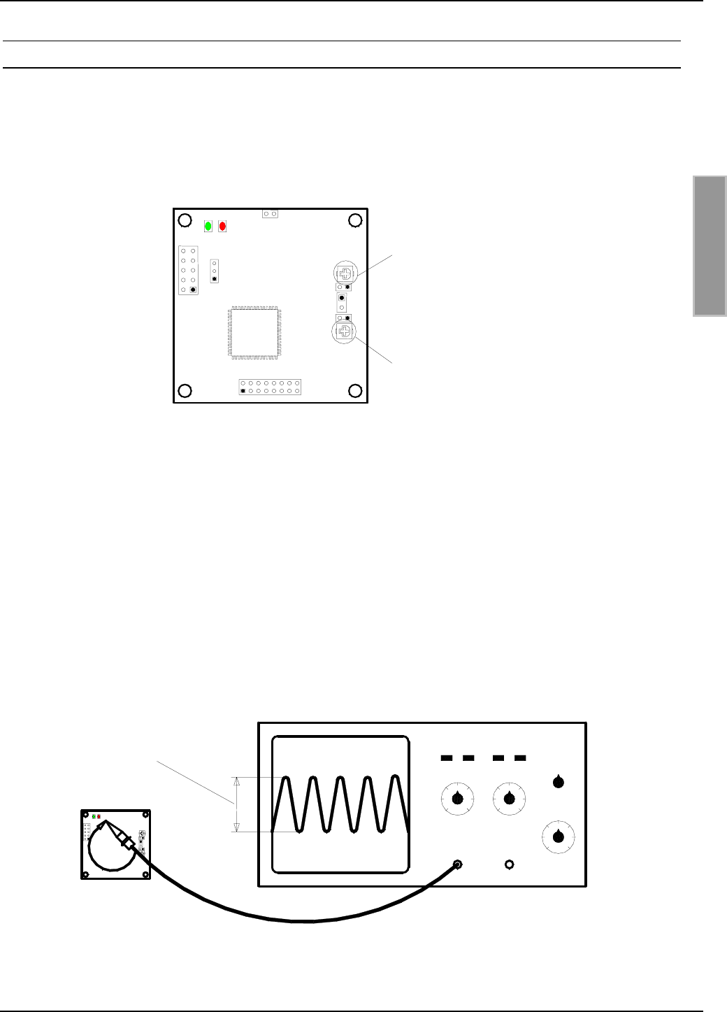
8.4.3. Retuning the internal antenna: Trim capacitor C65
The antenna of the ID ISC.M02 can be detuned as a result of various ambient conditions such as
nearby metal objects (see Section 8.5). This detuning can be compensated to some degree using
the trim capacitor C65.
Fig.: 3.4.3-1: Trim capacitor for retuning the antenna
The integrated antenna can be retuned with the aid of an oscilloscope (bandwidth ≥ 20 MHz). To
do this, short the GND terminal of the oscilloscope probe with the probe point and hold it over the
circuit board of the ID ISC.M02. The probe then forms a measuring loop for the radiated magnetic
field of the ID ISC.M02. The distance between the oscilloscope probe and the ID ISC.M02 should
be between 0 and 3 cm.
Use the software command „RF-ON“ (0x6A) to turn on the HF field of the ID ISC.M02. A 13.56
MHz signal should be visible on the oscilloscope screen.
To tune the internal antenna, now set the signal amplitude of the 13.56 MHz signal to maximum
using trim capacitor C65.
Bild 3.4.3-2: Configuration for tuning the internal antenna
C73
J2
J3
X2
X3
X4
X1
J1
V2
V1
C65
Trim capacitor C73:
DO NOT CHANGE !!!
Trim capacitor C65:
Retuning the
internal antenna
ID ISC.M02
Turn C65 to set amplitude
to maximum

OBID®Installation ID ISC.M02
FEIG ELECTRONIC GmbH Page 38 of 42 M20301-0de-ID-B.doc
E N G L I S H
Use caution when the maximum value of the signal amplitude is reached at the minimum or maxi-
mum position of the trim capacitor (Fig. 3.4.3-3). This usually means the antenna is too severely
detuned by the surroundings and can no longer be fully compensated by the trim capacitor.
Beschriftung
Minimale
Kapazität
Maximale
Kapazität
Fig. 3.4.3-3: Minimum and maximum position of the trim capacitor C65
After the antenna has bee tuned, check it again for maximum range and any communication gaps.
NOTE:
• Notwithstanding the possibility of retuning the antenna as described here, the distance
between the reader and the surrounding metal surfaces must be at least 3 cm. Note that
even other circuit boards may act like metal objects depending on how much copper
they contain.
Labeling
Minimum
capacitance
Maximum
capacitance

OBID®Installation ID ISC.M02
FEIG ELECTRONIC GmbH Page 39 of 42 M20301-0de-ID-B.doc
E N G L I S H
8.5. Installation notes
Be aware of the following possible environmental factors when installing an ID ISC.M02 into an-
other device :
• Effects from nearby metal objects
⇒ Detuning of the integrated antenna
⇒ Impaired propagation of the antenna’s magnetic field
• EMC effects on cables
⇒ Impaired communication between reader and transponder
• EMC effects from magnetic fields
⇒ Impaired communication between reader and transponder
8.5.1. Metallic surroundings
When installing an ID ISC.M02 into another device, be sure that there are no metal surfaces or
objects in the direct vicinity of the reader if possible. These can detune the antenna and thus re-
duce the magnetic field of the integrated antenna. This will in turn result in reduced read distances
for the reader.
The distance between the reader and a metal surface should be at least 3 cm. Note that
even other circuit boards may act line metal objects depending on how much copper they
contain.
If a metallic surrounding cannot be avoided, stable function should at least be ensured by keeping
the distance as great as possible.
The area between the antenna and transponder as well as the area on the other side of the trans-
ponder should also be kept clear of metal parts.
Since any change in the metallic environment will result in detuning of the integrated antenna and
therefore to impaired function, no moving metal parts, such as metallic fans, should be allowed in
the vicinity of the reader.
8.5.2. EMC effects on cables
In spite of the internal EMC filters inside the reader, high levels of noise on the supply voltage can
result in impairment of the communication between the reader and transponder.
When installing an ID ISC.M02 into another device, be sure therefore that a clean, noise-free
power supply is used.

OBID®Installation ID ISC.M02
FEIG ELECTRONIC GmbH Page 40 of 42 M20301-0de-ID-B.doc
E N G L I S H
8.5.3. EMC effects from magnetic fields
Since in this type of RF-ID-Technology the communication between the reader and transponder
takes place by modulation of a magnetic field, alternating magnetic fields in the vicinity of the an-
tenna can have a negative impact on its function.
Sources of such magnetic interference fields include coils within a primary or secondary switching
power supply.
When determining the position of the reader and antenna within a device, check the device for any
possible sources of interference as described above. If necessary, use shielding to suppress such
interference.

OBID®Installation ID ISC.M02
FEIG ELECTRONIC GmbH Page 41 of 42 M20301-0de-ID-B.doc
E N G L I S H
9. Radio Approvals
9.1. Europe (CE)
When used according to regulation, this radio equipment conforms with the basic requirements of
Article 3 and the other relevant provisions of the R&TTE Guideline 1999/E6 dated March 99.
9.2. USA (FCC)
FCC ID: PJMISCM02
This device complies with Part 15 of the FCC Rules. Operation is subject to the following
two conditions:
(1) this device may not cause harmful interference, and
(2) this device must accept any interference received, including interference that may
cause undesired operation.
Unauthorized modifications may void the authority granted under Federal communica-
tions Commission Rules permitting the operation of this device.
This device is labeled with an FCC ID number.
If this label is not visible when installed in an end device, the outside of the device MUST
also display a label referring to the enclosed module.
Wording on the label similar to the following shall be used:
This device contains transmitter module FCC ID PJMISCM02
At the time of this printing, the antennas listed below were the only antennas approved for
use with the ID ISC.M02 module. Use of other antennas must be approved by
FEIG ELECTRONIC GmbH.
Antennas approved: ID ISC.ANT100100; ID ISC.ANT4030

OBID®Installation ID ISC.M02
FEIG ELECTRONIC GmbH Page 42 of 42 M20301-0de-ID-B.doc
E N G L I S H
10. Technical Data
Mechanical Data
• Dimensions ( W x H x D ) 50mm x 50mm x 14 mm
• Connector 10 pol. Pin-Connector
Electrical Data
Supply voltage
Version –B 5 V DC ± 5%
• Power Consumption max. 1 W
• Operating Frequency 13.56 MHz
• RF Transmitting Power 90 mW ± 2 dB
• Antenna Internal Antenna, 48mm x 48mm
Optional: external Antenna
• Interfaces
Version –B RS232 – Level TTL, Data /Clock-Interface
Functional Characteristics
• EEPROM (for parameters) 1 kB
(10.000 write cycles)
• FLASH 64 kB
(software update on interface possible)
• Supported Transponders • ISO15693 (I•Code SLI, Tag-It HFI, my-d vicinity,
STM LRI512), I•Code 1
• Optional:
SAM (Security Access Module),
e.g. for my-d vicinity
• Optical Indicators 2 LED´s
Ambient
• Temperature Range
– Operating
– Storage
-20°C to +70°C
-40°C to +85°C
Applicable Norms
• Radio Approval
– Europe
– USA
EN 300 330
FCC 47 CFR Part 15
• EMC EN 301 489
• Safety EN 60950