Feig Electronic LRM200A Tag Reader System for industrial applications User Manual
Feig Electronic GmbH Tag Reader System for industrial applications Users Manual
Manual
M00602-1e-ID-B.DOC
OBID
i
-scan
Installation Instructions
ID ISC.LRM200-A/B

Identification System OBID
i-scan
Page 2 of 20 FEIG ELECTRONIC GmbH
Copyright 2000 by FEIG ELECTRONIC GmbH
Lange Straße 4
D-35781 Weilburg-Waldhausen
Germany
http://www.feig.de
Edition: er/01/01/04 - m00602-1e-id-b.doc
With the edition of this manual, all previous editions become void. Indications made in this manual may be changed
without previous notice.
The reproduction of this document as well as the utilization and communication of its contents are strictly forbidden, as
far as not expressly conceded. Any contravention will lead to a liability for damages. All rights reserved for the case of
patent grant respectively the registration of a utility or design.
Composition of the information in this manual has been done to the best of our knowledge. FEIG ELECTRONIC GmbH
does not guarantee the correctness and completeness of the details given in this manual and may not be held liable for
damages ensuing from incorrect or incomplete information. Since, despite all our efforts, errors may not be completely
avoided, we are always grateful for your useful tips.
The installation instructions given in this manual are based on advantageous boundary conditions. FEIG ELECTRONIC
GmbH does not give any guarantee promise for perfect function of an OBID®-system in cross surroundings.
FEIG ELECTRONIC GmbH assumes no responsibility for the use of any information contained in this manual and
makes no representation that they free of patent infringement. FEIG ELECTRONIC GmbH does not convey any license
under its patent rights nor the rights of others.
OBID® and i-
scan
® are registered trademarks of FEIG ELECTRONIC GmbH.

Installation Instructions ID ISC.LRM200-A/B
FEIG ELECTRONIC GmbH Page 3 of 20
Contents:
1. Safety Instructions / Warning ......................................................................................4
2. Features of the ID ISC.LRM200-A/B Reader Module ..................................................5
2.1. Features .............................................................................................................................5
2.2. Available modules .............................................................................................................5
3. Installation and wiring ..................................................................................................6
3.1. Terminals, sockets and switches.....................................................................................7
3.2. Antenna connection ..........................................................................................................8
3.3. Supply voltage ...................................................................................................................9
3.4. X7: Inputs (optocoupler isolated)...................................................................................10
3.5. X6: Output (optocoupler isolated)..................................................................................11
3.6. X11: Relay ........................................................................................................................12
3.7. X9: RS485 interface .........................................................................................................13
3.8. X10: RS232 interface .......................................................................................................14
4. Control and display elements ....................................................................................15
4.1. LED´s................................................................................................................................15
4.2. Buttons / switches...........................................................................................................16
5. Startup .........................................................................................................................17
5.1. Interface configuration using jumpers...........................................................................17
5.2. Setting addresses for bus operation..............................................................................18
6. Technical Data for ID ISC.LRM200-A/B .....................................................................19

Identification System OBID
i-scan
Page 4 of 20 FEIG ELECTRONIC GmbH
1. Safety Instructions / Warning
Read before startup !
• The device may be used only for the purpose intended by the manufacturer.
• The Installation Instruction should be kept in an accessible location and handed out to every
user and maintenance person.
• Non-approved modifications and the use of replacement parts and accessories which have not
been purchased or recommended by the manufacturer of the device may cause fires, electrical
shocks and injury. This will furthermore result in exclusion of liability and loss of warranty on
the part of the manufacturer.
• The warranty conditions in effect at the time of purchase shall be considered valid. No liability
is assumed for inappropriate, improper manual or automatic setting of parameters for a device
or for improper use of a device.
• Repairs are to be performed only by the manufacturer.
• Hookup, startup, maintenance, measuring and calibration work on the device must be per-
formed only by electrical specialists who have received the relevant accident prevention train-
ing.
• When operating devices with probably live wires, respect the valid security regulations.
• Before opening the device always turn off the supply voltage and use a test instrument to verify
that the device is unpowered.
• The fact that the indicator lamp is off does not necessarily mean that the device has been dis-
connected from the power supply or that it is without power.
• All work on the device including installation must be in conformance with national electrical
regulations as well as with local code.
• The device must be installed and electrically connected in accordance with the recognized
technical regulations in the country where it is being installed and according to other regional
codes..
• The base plate and the attached heat dissipater may become quite hot during operation.

Installation Instructions ID ISC.LRM200-A/B
FEIG ELECTRONIC GmbH Page 5 of 20
2. Features of the ID ISC.LRM200-A/B Reader Module
2.1. Features
The ID ISC.LRM200-A/B Reader Module has been developed for reading passive data tags, so-
called „Smart Labels“, at an operating frequency of 13.56 MHz. It is suitable for all applications in
which long reading distances are required. Depending on the specific Reader Module used, a ba-
sic antenna (ID ISC.LRM200-A) or a basic antenna plus complementary antenna (ID ISC.LRM200-
B) may be connected to the Reader.
An anti-collision function allows reading of up to 30 transponders at a time.
The Reader Module electronics is mounted on a rigid, 6 mm thick aluminum base plate. The mod-
ule has two digital inputs, two digital outputs, a relay output and an asynchronous interface which
can be configured as RS232 or RS485.
The configurability of the interfaces also allows the module to be operated on an RS485 data bus.
The address can be assigned either through software or hardware (3 DIP switches).
2.2. Available modules
The following models are available:
Model Description
ID ISC.LRM200-A For use with a basic antenna
ID ISC.LRM200-B For use with a basic/complementary antenna combination
Identification System OBID
i-scan
Page 6 of 20 FEIG ELECTRONIC GmbH
3. Installation and wiring
The Reader Module is designed for installation on a heat sink. Mounting is accomplished using the
∅ 4.5 mm holes located in each corner of the base plate (see Fig. 3-1).
To fully exploit the performance of the Reader Module, the heat sink should have a thermal resis-
tance RThK of max. 0.8 K/W. When attaching the Reader Module to the heat sink you should strive
for a little heat transfer resistance between the base plate and the heat sink as possible. The use
of heat sink compound is recommended.
If the antenna is properly tuned and there is sufficient air convection along the mounting plate, the
ID ISC.LRM200 can be operated without an additional heat sink at up to 4W of power. Note here
however that detuning of the antenna can result in additional heating of the Reader. In such cases
the Reader regulates its output power down until the upper temperature limit of its final stage is
reached again.
Fig. 3-1: Dimensional drawing of the ID ISC.LRM200-A/B Reader
150, 00 mm
160, 00 mm
100 mm
110 mm
120 mm
6 mm
43 mm
69 mm
ø 4, 5 mmø 4, 5 mm
ø 4, 5 mmø 4, 5 mm
Installation Instructions ID ISC.LRM200-A/B
FEIG ELECTRONIC GmbH Page 7 of 20
3.1. Terminals, sockets and switches
Fig. 3.1-1: Top view: Upper and lower circuit board
X7 X9 X10X6
J405
J407 J403
J400
J8 J1
X19
J350
X20
J402
J401
S1
X16
X15
J3
J2
X13
X14
J51 J6J50
X21
J5
J4
X18
X11
S2
ON
OFF
1 2 3 4
X3 X1
X2
Lower circuit board
Upper circuit board
V1
V2
V3
V4
V5

Identification System OBID
i-scan
Page 8 of 20 FEIG ELECTRONIC GmbH
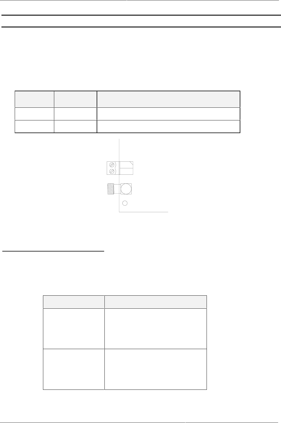
3.2. Antenna connection
Two SMA sockets are provided on the lower circuit board for connecting the basic antenna or, in
the case of ID ISC.LRM200-B, the basic/complementary antenna combination. The maximum
tightening torque for the SMA socket is 0.45 Nm.
Terminal Description
X1 For connecting the complementary antenna
(only ID ISC.LRM200-B)
X2 For connecting the basic antenna
(Input impedance 50Ω)
Notes:
• The input impedance of the basic antenna should be calibrated to a value of 50 Ω ± (3 Ω
∠ 3°).
• To achieve optimum read distances the length of the antenna lead-in cables should be
3.6 m ±0.1 m.
• When connecting an antenna, ensure that it does not exceed the limit values allowed by
the national regulations for radio emissions.
Installation Instructions ID ISC.LRM200-A/B
FEIG ELECTRONIC GmbH Page 9 of 20
3.3. Supply voltage
The supply voltage of 24 VDC is connected on Terminal X3 on the lower circuit board.
The cable length between the power supply and the Reader Module must not exceed 3 m.
Note:
• Reversing the power supply wires may destroy the device.
Terminal Name Description
X3 / Pin 1 +24V + 24 V DC supply voltage
X3 / Pin 2 GND Supply voltage ground
X3
X1
1
2+24 V DC
GND
!
Fig. 3.3-1 : Connecting the supply voltage
Power supply recommendations :
To exploit the full performance of the Reader Module, you should select a sufficiently regulated
and noise-filtered power supply (ripple = max. 20 mV). When using switching power supplies be
sure that the internal switching frequency is below 300 kHz.
Model Manufacturer
DRP-60-I LAMBDA Electronics GmbH
Josef-Hund-Str. 1
D-77855 Achern
Tel.: +49 (0) 7841 50 00
SilverLine SL 2.5 PULS GmbH
Arabellastraße 15
D-81925 München
Tel.: +49 (0) 89 9278 0
Identification System OBID
i-scan
Page 10 of 20 FEIG ELECTRONIC GmbH
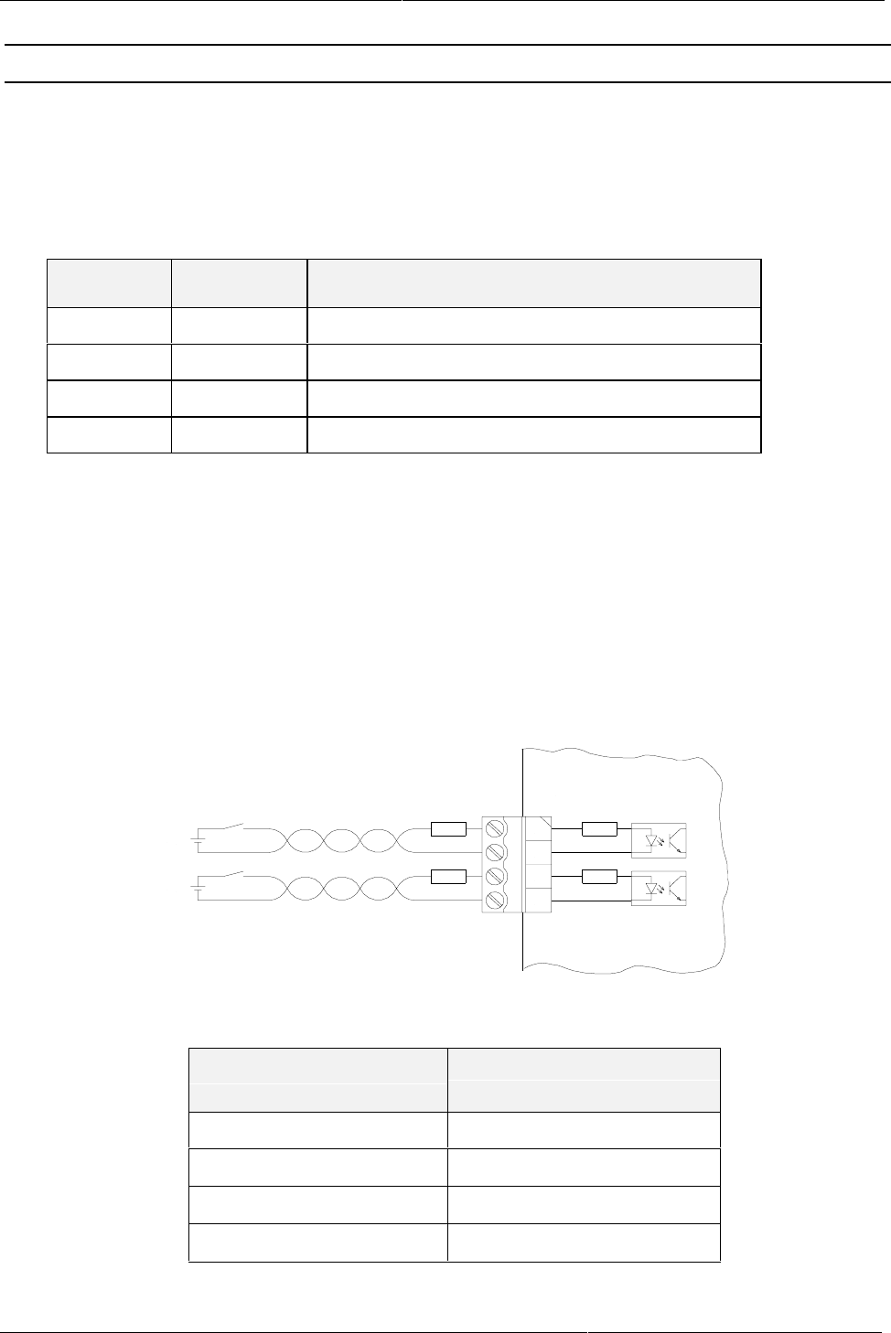
3.4. X7: Inputs (optocoupler isolated)
The optocoupler inputs on Terminal X7 are galvanically isolated from the Reader electronics and
must therefore be powered by a separate external DC supply. The input LED’s on the optocou-
plers have an internal input series resistor of 500 Ω. For supply voltages above 10V the input cur-
rent must be limited to max. 20 mA by an additional external dropping resistor (see Table 3.4-1).
Terminal Name Description
1 IN1+ + Input 1
2 IN1- - Input 1
3 IN2+ + Input 2
4 IN2- - Input 2
For cable lengths greater than 3 m use shielded cable.
Notes:
• The inputs are designed for a maximum input voltage of 24 V DC and an input current of
maximum 20 mA
• Reversing the polarity or overloading the inputs will destroy the unit
• The supply voltage of the Reader may not be used for driving the inputs, since the
added noise may result in reduced effective reading distances.
Fig. 3.4-1: Internal and possible external wiring of the optocoupler inputs
External voltage Uext Required external dropping
resistor Rext
5 V ... 10 V ---
11 V ... 15 V 270 Ω
16 V ... 20 V 560 Ω
21 V ... 24 V 820 Ω
Table 3.4-1: Required external dropping resistor Rext
X7
2
3
4
IN1 +
IN1 -
IN2 +
IN2 -
R
1
int
R
int
R
ext
R
ext
ID ISC.LRM200
U
ext.
U
ext.

Installation Instructions ID ISC.LRM200-A/B
FEIG ELECTRONIC GmbH Page 11 of 20
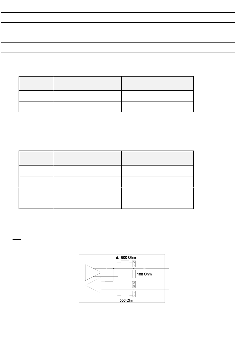
3.5. X6: Output (optocoupler isolated)
The transistor connections, collector and emitter, of the two optocoupler outputs are galvanically
isolated from the Reader electronics and brought out on Terminal X8 without any additional cir-
cuitry. The outputs must therefore be supplied externally.
Terminal Name Description
1O1-CCollector – Output 1
2 O1-E Emitter – Output 1
3 O2-C Collector – Output 2
4 O2-E Emitter – Output 2
For cable lengths greater than 3 m use shielded cable.
Notes:
• The outputs are configured for max. 24 V DC / 30 mA.
• Reversing the polarity or overloading the outputs will destroy the unit.
• The outputs are designed to switch resistive loads only.
Fig. 3.5-1: Internal wiring of the optocoupler outputs
X6
1
2
3
4
O1-C
O1-E
O2-C
O2-E
ID ISC.LR200

Identification System OBID
i-scan
Page 12 of 20 FEIG ELECTRONIC GmbH
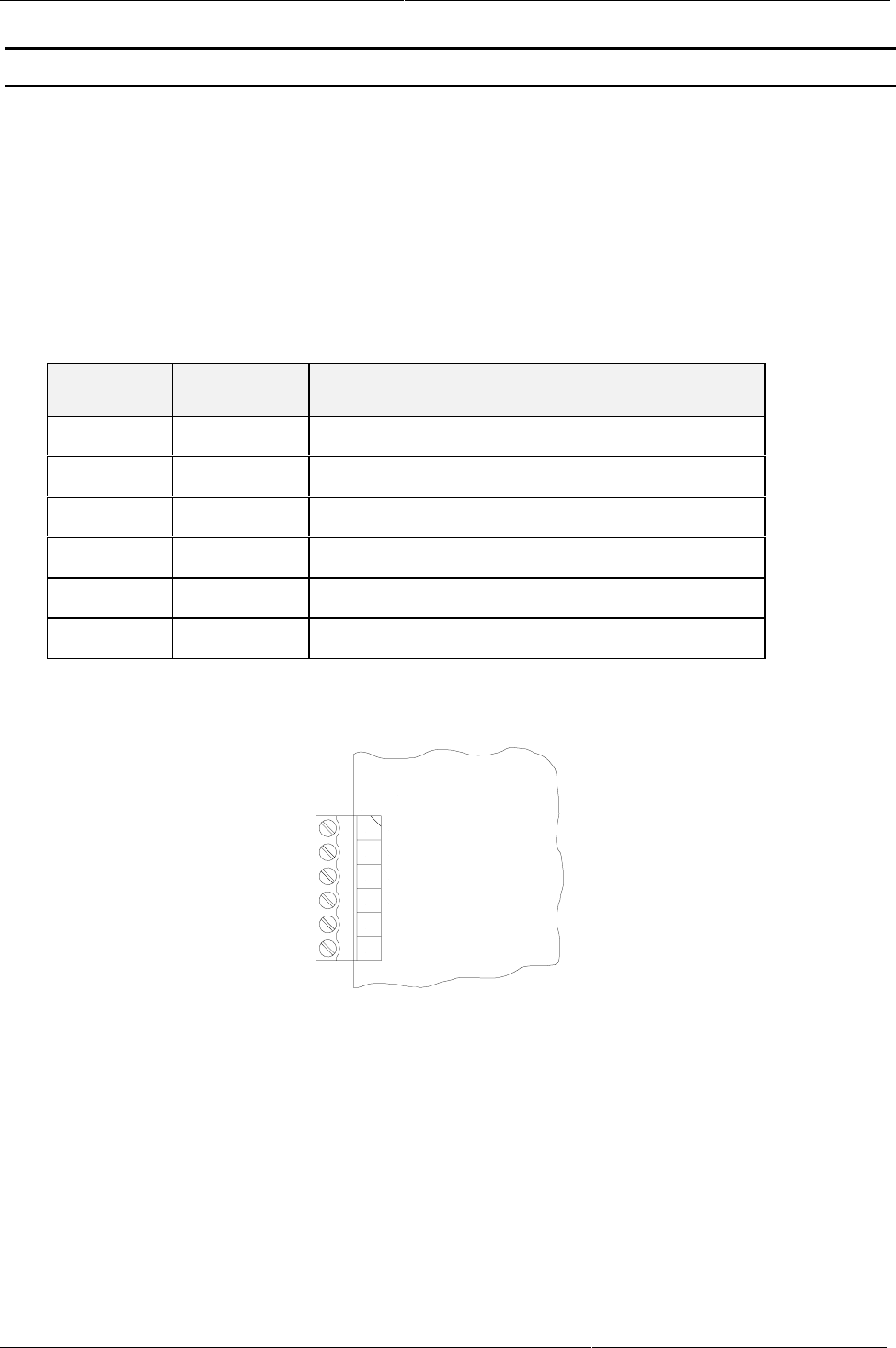
3.6. X11: Relay
The relay output is a change-over contact.
Terminal Name Description
1 COM Working contact
2 NC Normally closed contact
3 NO Normally open contact
Notes:
• The relay outputs are configured for max. 24 V DC / 60 W.
• The relay outputs are designed to switch resistive loads only. If using an inductive load,
the relay contacts must be protected by means of an external protection circuit.
Installation Instructions ID ISC.LRM200-A/B
FEIG ELECTRONIC GmbH Page 13 of 20
3.7. X9: RS485 interface
The asynchronous interface can be configured for RS485 or RS232 (see Section 5.1: Interface
configuration using jumpers).
The RS485 interface is configured on X9.
The transmission parameters can be software configured.
Configuration for X9 (RS485 interface):
Terminal Name Description
1 4xxB RS485 – (B +)
2 4xxA RS485 - (A -)
3 4xxG RS485 – GND
4 422Y n.c.
5 422Z n.c.
6 422G n.c.
Fig. 3.7-1 : Configuring the RS485 interface
X9
1
2
3
4
ID ISC.LR200
5
6n.c.
n.c.
n.c.
RS485 - GND
RS485 - (A-)
RS485 - (B+)
Identification System OBID
i-scan
Page 14 of 20 FEIG ELECTRONIC GmbH
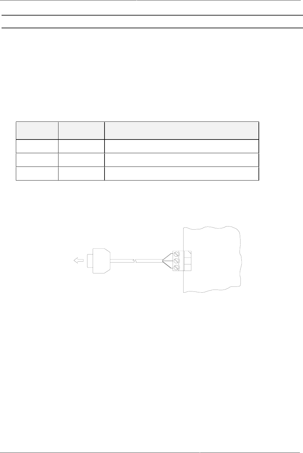
3.8. X10: RS232 interface
The asynchronous interface can be configured for RS485 or RS232 (see Section 5.1: Interface
configuration using jumpers).
The RS232 interface is configured on X10.
The transmission parameters can be software configured.
Configuration for X10 (RS232 interface):
Terminal Name Description
1GNDRS232 – GND
2 RxD RS232 - RxD
3 TxD RS232 - TxD
X10
1
2
3
GND
RxD
TxD
ID ISC.LR200
9-pin sub-D female
Pin 5 X10 / 1
Pin 3 X10 / 2
Pin 2 X10 / 3
<−>
<−>
<−>
PC
Fig. 3.8-1 : Wiring example for connecting the RS232 interface

Installation Instructions ID ISC.LRM200-A/B
FEIG ELECTRONIC GmbH Page 15 of 20
4. Control and display elements
4.1. LED´s
Table 4.1-1 shows the configuration of the LED´s.
Name Description
LED V1 (green) "RUN-LED"
- Indicates proper running of the internal Reader software
- Flashing rate ca. 1 Hz
LED V2 (red) Diagnostic 1: RF communication / EEPROM status
- Short flashing indicates error-free communication with a trans-
ponder on the RF interface
- Flashes alternating with V1 after Reset following a software
update
- Flashes alternating with V1 in case a data error while reading
the parameters occurred following a Reset
LED V3 (red) Diagnostic 2: Host communication
- Short flashing indicates a protocol is being sent to the host on
the RS232/RS485 interface
LED V4 (red) Diagnostic 3: Reserved
LED V5 (red) Diagnostic 4: Reader initialization / RF error
- Comes on during Reader initialization after power-up or after a
reset.
- Comes on to indicate an error in the RF section of the Reader.
The error type can be read out via software on the
RS232/RS485 interface
Table 4.1-1: LED configuration

Identification System OBID
i-scan
Page 16 of 20 FEIG ELECTRONIC GmbH
4.2. Buttons / switches
Name Description
S1 Reset button
S2 1 - 3: Setting data bus addresses (0 ... 7)
4: not used
Note :
To set the bus address using S2, the Reader must be set to software address „0“ (factory
setting).
Installation Instructions ID ISC.LRM200-A/B
FEIG ELECTRONIC GmbH Page 17 of 20
5. Startup
5.1. Interface configuration using jumpers
Jumpers J400 – J401 are used to configure the asynchronous interface for RS232 or RS485.
Jumper RS232 RS485
400 1 - 2 2 - 3
401 1 - 2 2 - 3
Jumpers J403, J405 and J407 can be used to insert the termination resistors which may be re-
quired for the RS485 interface.
Jumper In Out
405 Pull-Up on RS485 - B No Pull-Up on RS485 - B
407 Pull-Down on RS485 - A No Pull-Down on RS485 - A
403 Termination resistor
RS485 - A ⇔ RS485 - B
No termination resistor
RS485 - A ⇔ RS485 - B
Note:
It is not possible to operate both RS232 and RS485 at the same time.
J405
J403
J407
RS485 - B+
RS485 - A-
Jumpers for RS485 interface

Identification System OBID
i-scan
Page 18 of 20 FEIG ELECTRONIC GmbH
5.2. Setting addresses for bus operation
For bus operation the Reader allows you to set the required bus address either using DIP switch
S2 or through the software.
a) Setting the bus address on S2 :
Addresses „0“ to „7“ can be set on S2.
To set the bus address using S2, the Reader must be set to software address „0“ (factory set-
ting).
Address Switch 1 Switch 2 Switch 3
0 OFF OFF OFF
1OFFOFF
ON
2OFF
ON OFF
3OFF
ON ON
4ON OFF OFF
5ON OFF ON
6ON ON OFF
7ON ON ON
b) Setting the bus address through software
Addresses are assigned through the host computer. The software is used to assign addresses “0”
to “253” to the Reader.
Note:
Since all Readers are factory set to Address 0, they must be connected and configured one
after the other.

Installation Instructions ID ISC.LRM200-A/B
FEIG ELECTRONIC GmbH Page 19 of 20
6. Technical Data for ID ISC.LRM200-A/B
Mechanical Data
• Dimensions ( W x H x D ) 120 x 160 x 69 mm
• Weight 650 g
Electrical Data
• Supply voltage 24 V DC +5%/-1%
Ripple : max. 20 mV
• Power consumption max. 60 W
• Operating frequency 13.56 MHz
• Transmitting power 0.5 to 10 W*
(software settable in 0.25W steps)
• Modulation 8% - 100%
(software settable)
• Antenna connection
- Basic antenna
- Complementary antenna (Model -
B)
1 x SMA socket (50Ω)
1 x SMA socket (50Ω)
• Outputs:
- 2 optocoupler
- 1 relay ( 1 x change-over)
24 V DC / 30 mA (galvanically isolated)
24 V DC / 60 W
• Inputs
– 2 optocoupler max. 24 V DC/ 20 mA
• Interfaces RS232 and RS485 (internally selectable)
* Depending on the output power an additional heat sink may be necessary

Identification System OBID
i-scan
Page 20 of 20 FEIG ELECTRONIC GmbH
Functional characteristics
• EEPROM (for parameters) 1 kB
(10,000 write cycles)
• RAM 256 kB
• FLASH 512 kB
(software update on interface possible)
• Supported transponders I•Code, Tag-it
(ISO transponder requires software update)
• Address setting for interface Optional :
- 3-position DIP switch (up to 8 addresses)
- Software (up to 254 addresses)
• Optical indicators 5 LED´s for status diagnostics
• Multi-Reader mode Protocol synchronization through use of the ex-
isting in- and outputs
Ambient
• Temperature range
- Operating
- Storage
-20°C to +65°C
-25°C to +70°C
• Vibration EN60068-2-6
10 Hz to 150 Hz :0.075 mm / 1 g
• Shock EN60068-2-27
Acceleration : 30 g
Applicable norms
• Radio approval
- Europe
- USA
EN 300 330
FCC 47 CFR Part 15
• EMC EN 300 683
• Safety
- Europe
- USA
EN 60950
UL 1950