Feig Electronic LRU2000 RFID Reader User Manual M60801 0de ID B
Feig Electronic GmbH RFID Reader M60801 0de ID B
UserManual.wiki
>
Feig Electronic
>
LRU2000 User Manual
User Manual
Navigation menu
Upload a User Manual
Namespaces
Wiki Guide
HTML
PDF
Info
Views
User Manual
Discussion / Help
Navigation
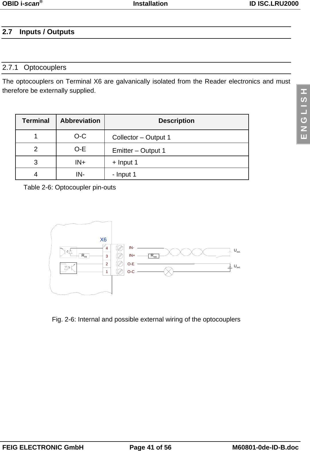
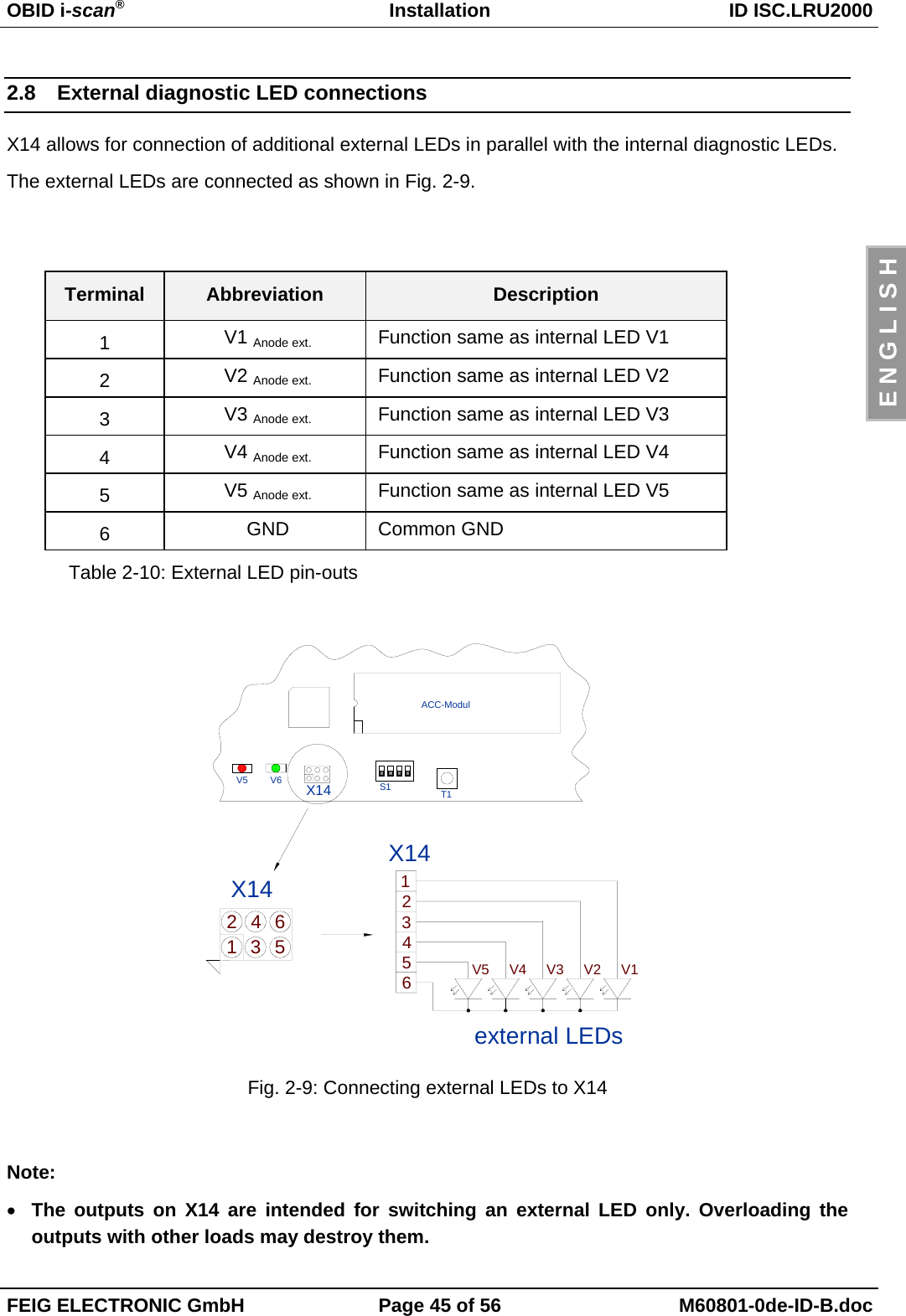
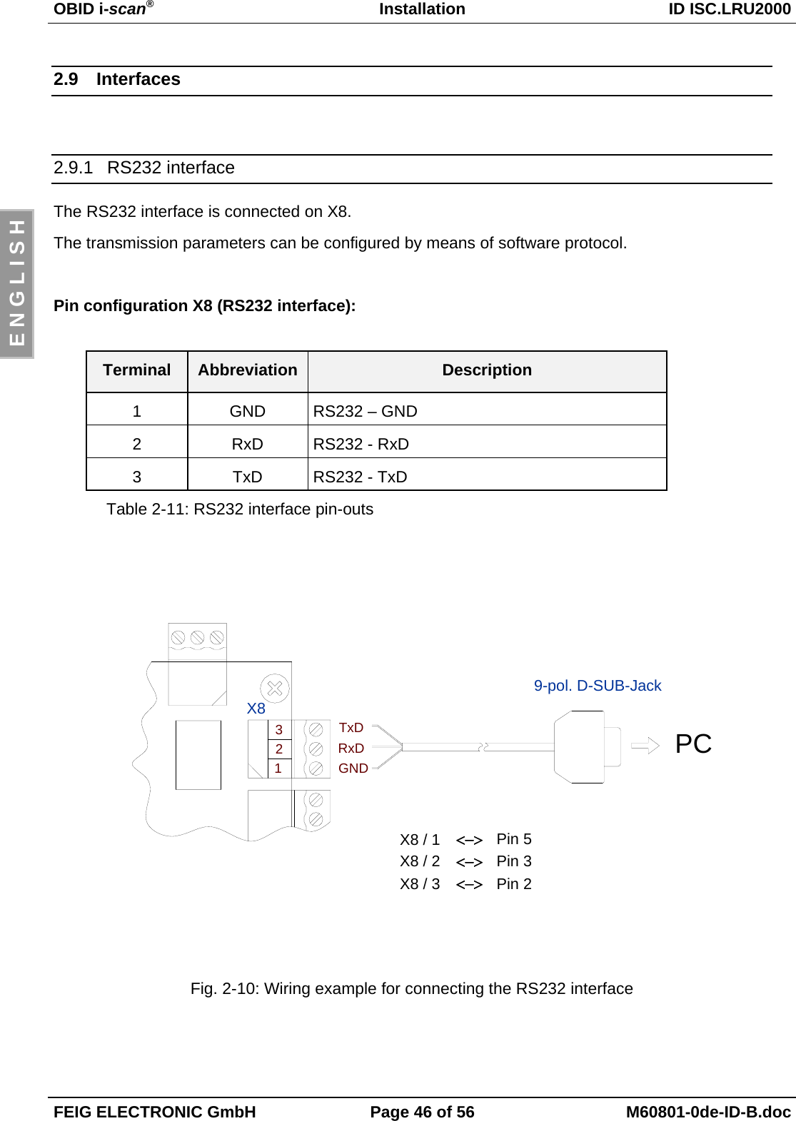
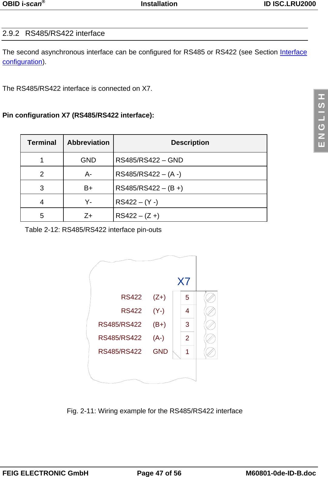
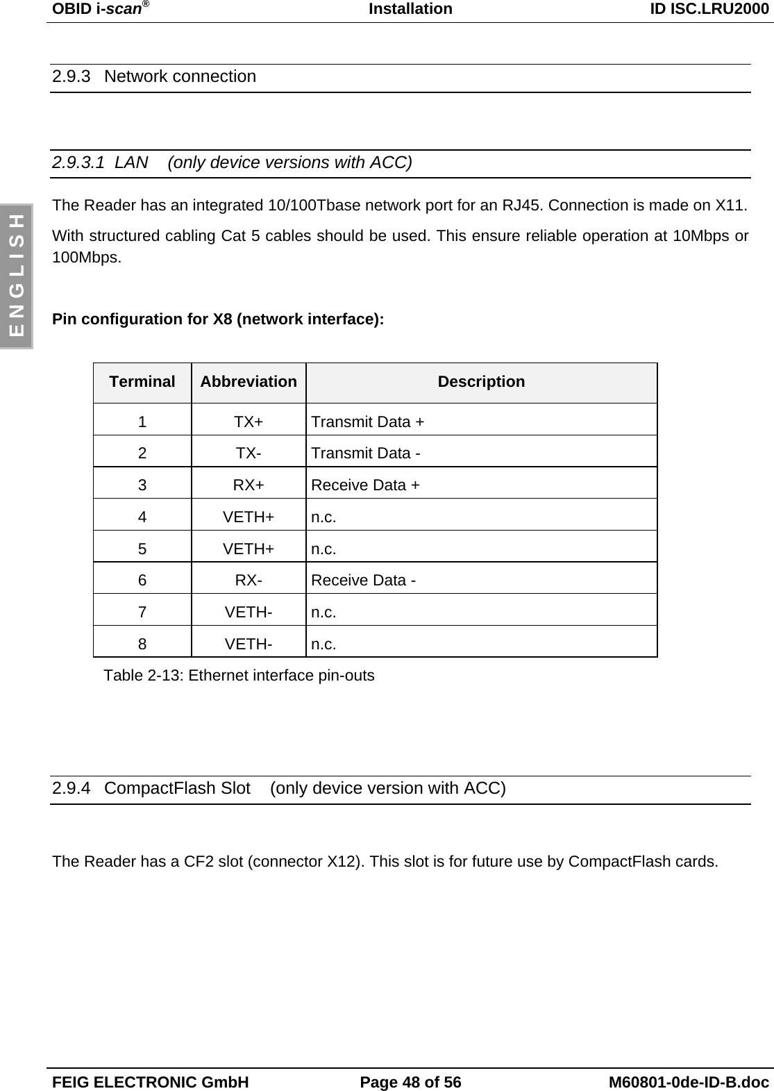
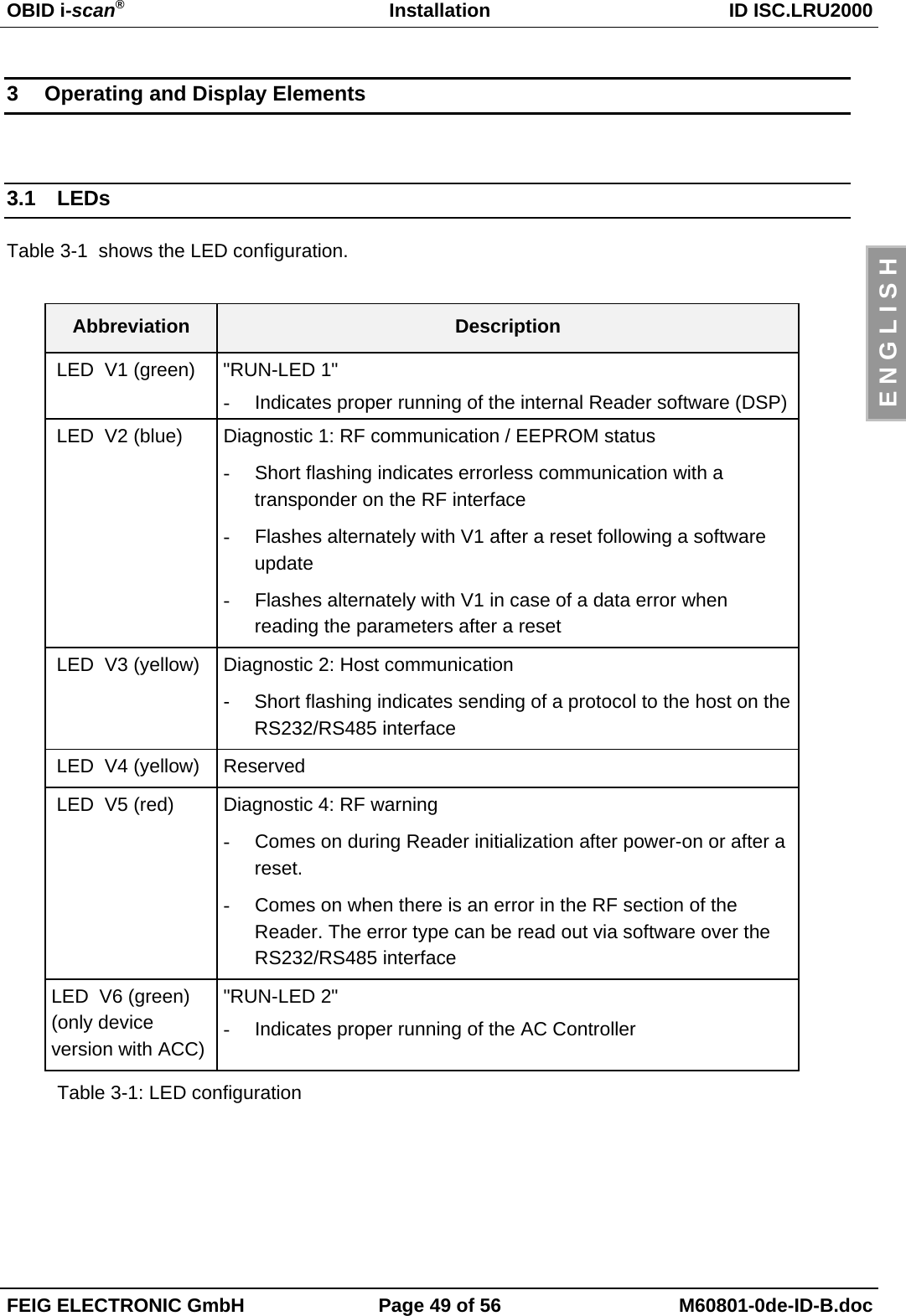
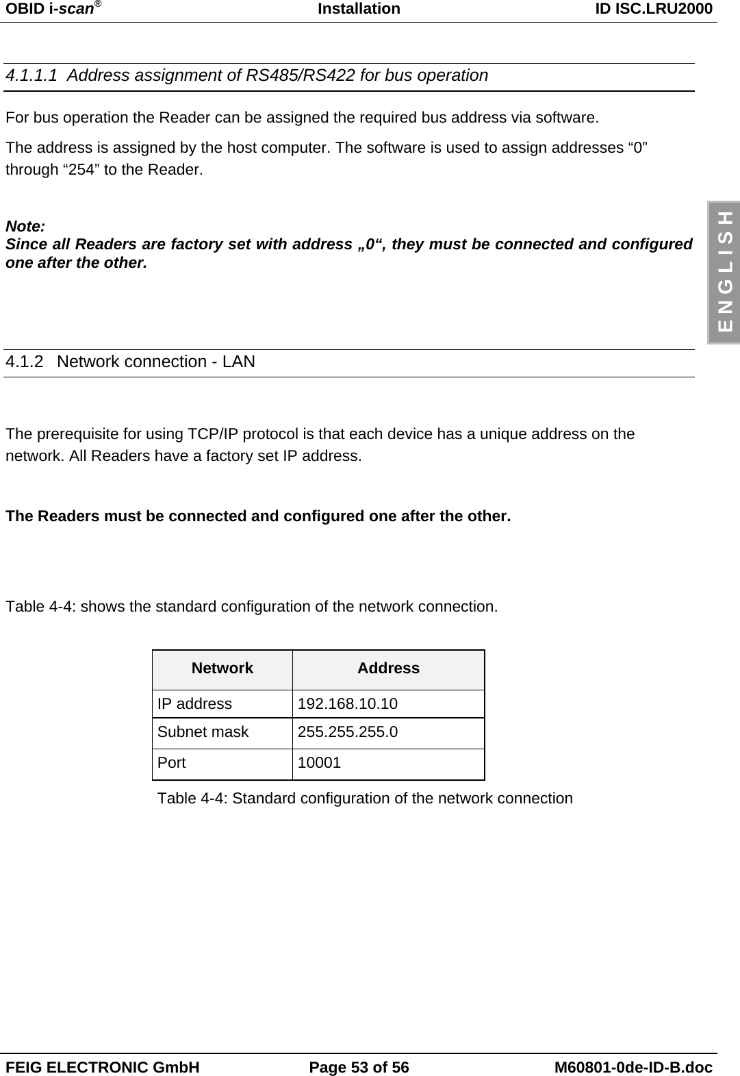
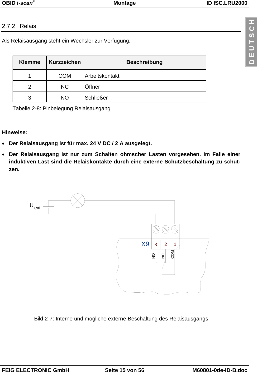
![OBID i-scan®Montage ID ISC.LRU2000FEIG ELECTRONIC GmbH Seite 9 von 56 M60801-0de-ID-B.docD E U T S C H2.3.1 KabelverschraubungenAn der Unterseite des Gehäuses befinden sich die Kabelverschraubungen. Bild 2-2: Montage-zeichnung zeigt die Anordnung und in Tabelle 2-3: Kabelverschraubungen ID ISC.LRU2000 istdargestellt, welche Kabelverschraubungen für die einzelnen Leitungen verwendet werden sollen.21 3958467Bild 2-2: MontagezeichnungKabelver-schraubung Größe Klemmbereich[mm] Beschreibung1 M 16 4.5 – 10 Anschlusskabel Antenne2 M 16 4.5 – 10 Anschlusskabel Antenne3 M 16 4.5 – 10 Anschlusskabel Antenne4 M 16 4.5 – 10 Anschlusskabel Antenne5 M 12 3.5 – 7 Spannungsversorgung6 M 16 4.5 – 10 Ein- / Ausgänge / Schnittstelle7 M 16 4.5 – 10 Ein- / Ausgänge / Schnittstelle8 M 12 3.5 – 7 Ein- / Ausgänge / Schnittstelle9 M 25 9 – 17 Netzwerkanschluss (optional)Tabelle 2-3: Kabelverschraubungen ID ISC.LRU2000](https://usermanual.wiki/Feig-Electronic/LRU2000/User-Guide-746331-Page-9.png)

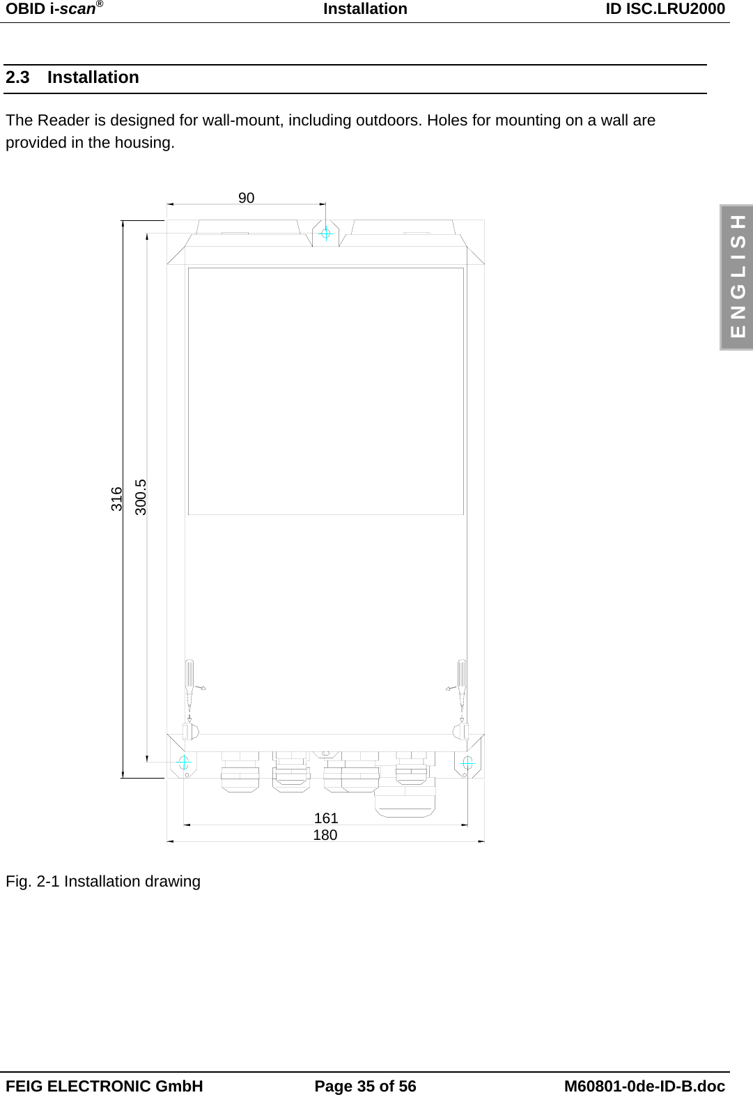
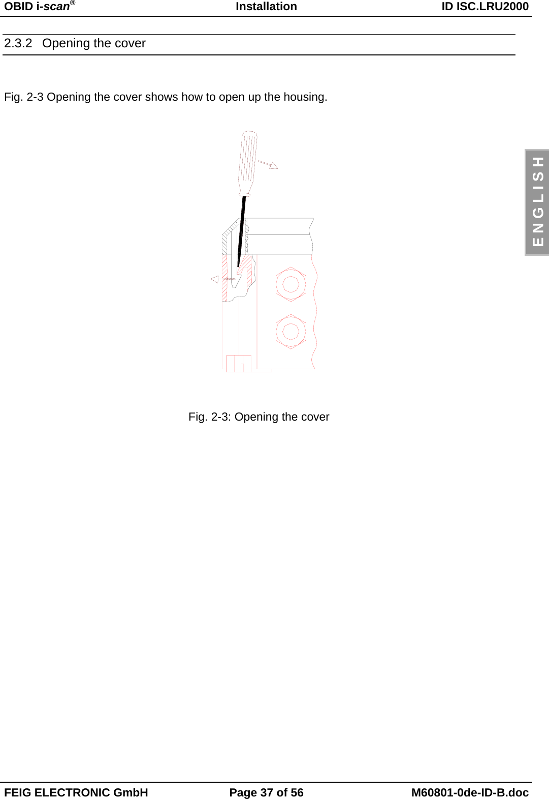
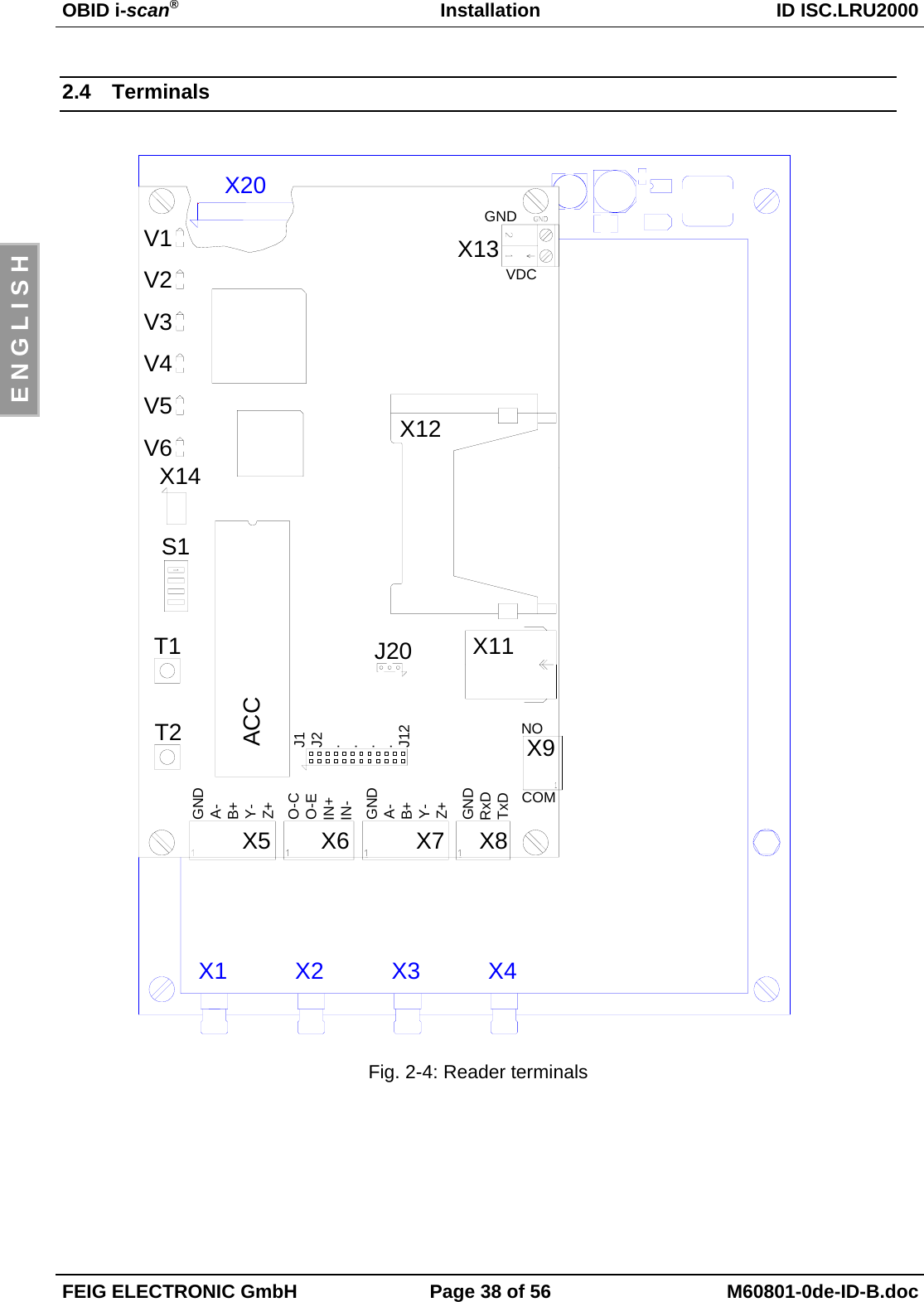
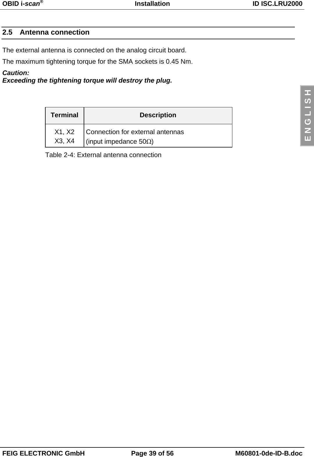
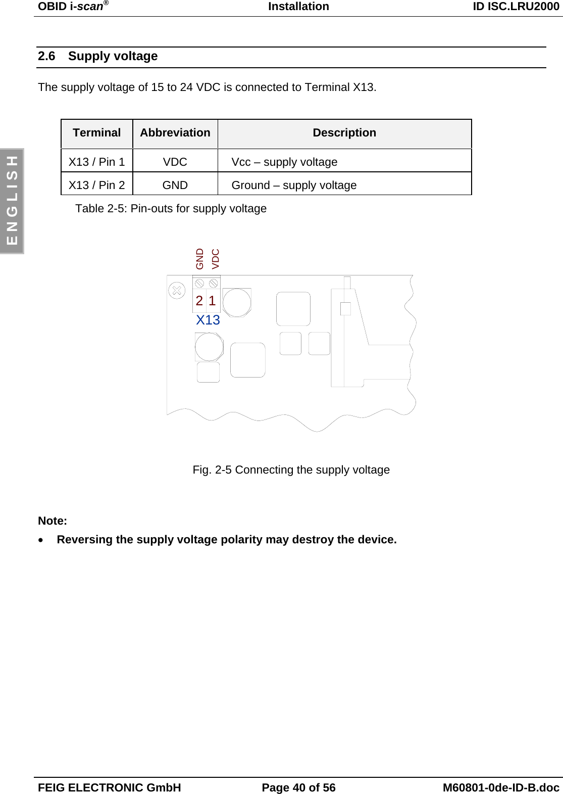
![OBID i-scan®Installation ID ISC.LRU2000FEIG ELECTRONIC GmbH Page 36 of 56 M60801-0de-ID-B.docE N G L I S H2.3.1 Cable glandsThe cable glands are located on the underside of the housing. Fig. 2-2: Installation drawing showsthe arrangement, and Table 2-3: Cable glands for ID ISC.LRU2000 indicates which cable glandsshould be used for the individual lines.21 3958467Fig. 2-2 Installation drawingCable gland Size Clampingrange[mm] Description1 M 16 4.5 – 10 Antenna cable2 M 16 4.5 – 10 Antenna cable3 M 16 4.5 – 10 Antenna cable4 M 16 4.5 – 10 Antenna cable5 M 12 3.5 – 7 Supply voltage6 M 16 4.5 – 10 In-/Outputs/Interface7 M 16 4.5 – 10 In-/Outputs/Interface8 M 12 3.5 – 7 In-/Outputs/Interface9 M 25 9 – 17 Network connection (optional)Table 2-3: Cable glands for ID ISC.LRU2000](https://usermanual.wiki/Feig-Electronic/LRU2000/User-Guide-746331-Page-36.png)