Feig Electronic LRU2000 RFID Reader User Manual M60801 0de ID B
Feig Electronic GmbH RFID Reader M60801 0de ID B
User Manual
MONTAGE
INSTALLATION
final
public (B)
2006-09-03
M60801-0de-ID-B.doc
OBI
D
i-scan
®
ID ISC.LRU2000
(deutsch / english)

OBID i-scan®Montage ID ISC.LRU2000
FEIG ELECTRONIC GmbH Seite 2 von 56 M60801-0de-ID-B.doc
D E U T S C H
deutsche Version ab Seite 3
english version from page 30
E N G L I S H

OBID i-scan®Montage ID ISC.LRU2000
FEIG ELECTRONIC GmbH Seite 3 von 56 M60801-0de-ID-B.doc
D E U T S C H
Hinweis
© Copyright 2004 - 2006 by
FEIG ELECTRONIC GmbH
Lange Strasse 4
D-35781 Weilburg-Waldhausen
Tel.: +49 6471 3109-0
http://www.feig.de
Alle früheren Ausgaben verlieren mit dieser Ausgabe ihre Gültigkeit.
Die Angaben in diesem Dokument können ohne vorherige Ankündigung geändert werden.
Weitergabe sowie Vervielfältigung dieses Dokuments, Verwertung und Mitteilung ihres Inhalts sind nicht
gestattet, soweit nicht ausdrücklich zugestanden. Zuwiderhandlung verpflichtet zu Schadenersatz. Alle
Rechte für den Fall der Patenterteilung oder Gebrauchsmuster-Eintragung vorbehalten.
Die Zusammenstellung der Informationen in diesem Dokument erfolgt nach bestem Wissen und Gewissen.
FEIG ELECTRONIC GmbH übernimmt keine Gewährleistung für die Richtigkeit und Vollständigkeit der An-
gaben in diesem Dokument. Insbesondere kann FEIG ELECTRONIC GmbH nicht für Folgeschäden auf
Grund fehlerhafter oder unvollständiger Angaben haftbar gemacht werden. Da sich Fehler, trotz aller Bemü-
hungen nie vollständig vermeiden lassen, sind wir für Hinweise jederzeit dankbar.
Die in diesem Dokument gemachten Installationsempfehlungen gehen von günstigsten Rahmenbedingun-
gen aus. FEIG ELECTRONIC GmbH übernimmt weder Gewähr für die einwandfreie Funktion in system-
fremden Umgebungen, noch für die Funktion eines Gesamtsystems, welches die in diesem Dokument be-
schriebenen Geräte enthält.
FEIG ELECTRONIC weist ausdrücklich darauf hin, dass die in diesem Dokument beschriebenen Geräte
nicht für den Einsatz mit oder in medizinischen Geräten oder für Geräte für lebenserhaltende Maßnahmen
konzipiert sind, bei denen ein Fehler eine Gefahr für menschliches Leben oder für die gesundheitliche Un-
versehrtheit zur Folge haben kann. Der Applikationsdesigner ist dafür verantwortlich geeignete Maßnahmen
zu ergreifen um Gefahren, Schäden oder Verletzungen zu vermeiden.
Geräte, die in diesem Dokument beschrieben werden dürfen nicht im "Transport Markt" verkauft, benutz,
geleast, angeboten oder anderweitig übertragen, exportiert und importiert werden. Als "Transport Markt" sind
folgende Anwendungen definiert: (I) Elektronische Maut und Verkehrs Management (ETTM), (II) öffentliche
Kraftfahrzeugzulassung, -Registrierung und -Kontrolle (III) Verfolgung von schienengebundenen Lokomoti-
ven und Wagons (IV) erdgebundene Managementsysteme für Flughafen Transporte (GTMS) und Taxi Ab-
fertigung (V) kostenpflichtige Parksysteme und (VI) Fahrzeug initiierte mobile Bezahlsysteme, bei denen der
RFID Transponder bereits bei Auslieferung montiert ist, aber nicht beim Fahrzeughersteller in das Fahrzeug
integriert wurde.
FEIG ELECTRONIC GmbH übernimmt keine Gewährleistung dafür, dass die in diesem Dokument enthal-
tenden Informationen frei von fremden Schutzrechten sind. FEIG ELECTRONIC GmbH erteilt mit diesem
Dokument keine Lizenzen auf eigene oder fremde Patente oder andere Schutzrechte.
OBID® und OBID i-scan® ist ein eingetragenes Warenzeichen der FEIG ELECTRONIC GmbH

OBID i-scan®Montage ID ISC.LRU2000
FEIG ELECTRONIC GmbH Seite 4 von 56 M60801-0de-ID-B.doc
D E U T S C H
Inhalt
1 Sicherheits- und Warnhinweise - vor Inbetriebnahme unbedingt lesen 6
2 Leistungsmerkmale der Readerfamilie ID ISC.LRU2000 7
2.1 Leistungsmerkmale.......................................................................................................7
2.2 Verfügbare Readertypen...............................................................................................7
2.3 Montage..........................................................................................................................8
2.3.1 Kabelverschraubungen ...................................................................................................9
2.3.2 Öffnen des Deckels .......................................................................................................10
2.4 Anschlussklemmen.....................................................................................................11
2.5 Antennenanschluss ....................................................................................................12
2.6 Versorgungsspannung ...............................................................................................12
2.7 Eingänge / Ausgänge..................................................................................................13
2.7.1 Optokoppler...................................................................................................................13
2.7.2 Relais ............................................................................................................................15
2.7.3 Readersynchronisation..................................................................................................16
2.8 Anschluss externer Diagnose-LEDs..........................................................................17
2.9 Schnittstellen...............................................................................................................18
2.9.1 RS232-Schnittstelle.......................................................................................................18
2.9.2 RS485/RS422 Schnittstelle ...........................................................................................19
2.9.3 Netzwerkanschluss .......................................................................................................20
2.9.4 CompactFlash-Steckplatz (nur Gerätevarianten mit ACC)..........................................20
3 Bedien- und Anzeigeelemente 21
3.1 LEDs .............................................................................................................................21
3.2 Taster / Schalter ..........................................................................................................22
4 Inbetriebnahme 23
4.1 Schnittstellenkonfiguration........................................................................................23
4.1.1 RS485/RS422 ...............................................................................................................23

OBID i-scan®Montage ID ISC.LRU2000
FEIG ELECTRONIC GmbH Seite 5 von 56 M60801-0de-ID-B.doc
D E U T S C H
4.1.2 Netzwerkanschluss - LAN .............................................................................................25
5 Funkzulassungen 26
5.1 Europa (CE)..................................................................................................................26
5.2 USA (FCC)....................................................................................................................26
6 Technische Daten 27

OBID i-scan®Montage ID ISC.LRU2000
FEIG ELECTRONIC GmbH Seite 6 von 56 M60801-0de-ID-B.doc
D E U T S C H
1 Sicherheits- und Warnhinweise - vor Inbetriebnahme unbedingt lesen
• Das Gerät darf nur für den vom Hersteller vorgesehenen Zweck verwendet werden.
• Beim Aufstellen des Gerätes im Geltungsbereich der FCC 47 CFR Part 15 ist ein Mindestab-
stand von 23cm zwischen Antenne und menschlichem Körper zu gewährleisten.
• Die Bedienungsanleitung ist zugriffsfähig aufzubewahren und jedem Benutzer auszuhändigen.
• Unzulässige Veränderungen und die Verwendung von Ersatzteilen und Zusatzeinrichtungen,
die nicht vom Hersteller des Gerätes verkauft oder empfohlen werden, können Brände, elektri-
sche Schläge und Verletzungen verursachen. Solche Maßnahmen führen daher zu einem
Ausschluss der Haftung und der Hersteller übernimmt keine Gewährleistung.
• Für das Gerät gelten die Gewährleistungsbestimmungen des Herstellers in der zum Zeitpunkt
des Kaufs gültigen Fassung. Für eine ungeeignete, falsche manuelle oder automatische Ein-
stellung von Parametern für ein Gerät bzw. ungeeignete Verwendung eines Gerätes wird keine
Haftung übernommen.
• Reparaturen dürfen nur vom Hersteller durchgeführt werden.
• Anschluss-, Inbetriebnahme-, Wartungs-, und sonstige Arbeiten am Gerät dürfen nur von Elekt-
rofachkräften mit einschlägiger Ausbildung erfolgen.
• Alle Arbeiten am Gerät und dessen Aufstellung müssen in Übereinstimmung mit den nationa-
len elektrischen Bestimmungen und den örtlichen Vorschriften durchgeführt werden.
• Beim Arbeiten an dem Gerät müssen die jeweils gültigen Sicherheitsvorschriften beachtet wer-
den.
• Besonderer Hinweis für Träger von Herzschrittmachern:
Obwohl dieses Gerät die zulässigen Grenzwerte für elektromagnetische Felder nicht über-
schreitet, sollten Sie einen Mindestabstand von 25 cm zwischen dem Gerät und Ihrem Herz-
schrittmacher einhalten und sich nicht für längere Zeit in unmittelbarer Nähe des Geräts bzw.
der Antenne aufhalten.

OBID i-scan®Montage ID ISC.LRU2000
FEIG ELECTRONIC GmbH Seite 7 von 56 M60801-0de-ID-B.doc
D E U T S C H
2 Leistungsmerkmale der Readerfamilie ID ISC.LRU2000
2.1 Leistungsmerkmale
Der Reader ist für das Lesen von passiven Datenträgern, sogenannten „Smart Labels“, mit einer
Betriebsfrequenz im UHF Bereich entwickelt.
2.2 Verfügbare Readertypen
Folgende Reader und Readermodule sind z.Z. verfügbar:
Readertyp Beschreibung
ID ISC.LRU2000-A-EU Gerätevariante mit ACC für Europa
ID ISC.LRU2000-A-FCC Gerätevariante mit ACC für USA
ID ISC.LRU2000i-A-EU Gerätevariante mit ACC und interner Antenne für Europa
ID ISC.LRU2000i-A-FCC Gerätevariante mit ACC und interner Antenne für USA
Tabelle 2-1: Readertypen
Readermodultyp Beschreibung
ID ISC.LRMU2000-B-EU Gerätevariante ohne ACC für Europa
ID ISC.LRMU2000-B-FCC Gerätevariante ohne ACC für USA
Tabelle 2-2: Readermodultypen
OBID i-scan®Montage ID ISC.LRU2000
FEIG ELECTRONIC GmbH Seite 8 von 56 M60801-0de-ID-B.doc
D E U T S C H
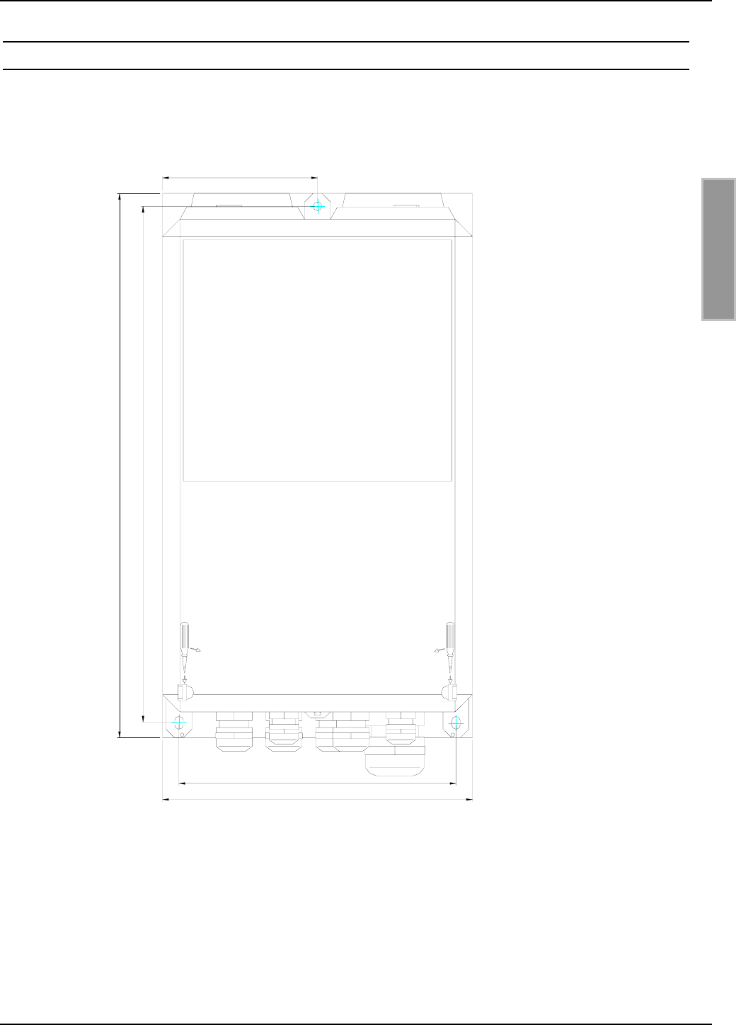
2.3 Montage
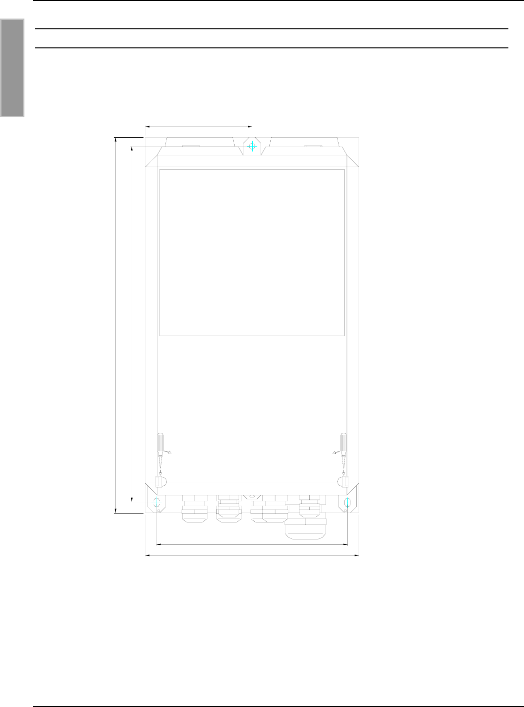
Der Reader ist für die Montage auf Wänden, auch im Freien, konzipiert. Zur Wandmontage befin-
den sich im Gehäuse vorgesehene Löcher.
Bild 2-1: Montagezeichnung
316
300.5
161
180
90
OBID i-scan®Montage ID ISC.LRU2000
FEIG ELECTRONIC GmbH Seite 9 von 56 M60801-0de-ID-B.doc
D E U T S C H
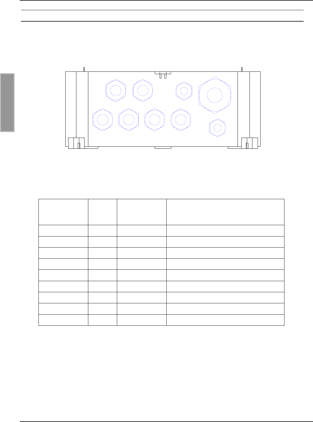
2.3.1 Kabelverschraubungen
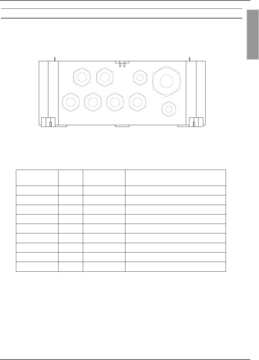
An der Unterseite des Gehäuses befinden sich die Kabelverschraubungen. Bild 2-2: Montage-
zeichnung zeigt die Anordnung und in Tabelle 2-3: Kabelverschraubungen ID ISC.LRU2000 ist
dargestellt, welche Kabelverschraubungen für die einzelnen Leitungen verwendet werden sollen.
21 3
9
5
8
4
67
Bild 2-2: Montagezeichnung
Kabelver-
schraubung Größe Klemmbereich
[mm] Beschreibung
1 M 16 4.5 – 10 Anschlusskabel Antenne
2 M 16 4.5 – 10 Anschlusskabel Antenne
3 M 16 4.5 – 10 Anschlusskabel Antenne
4 M 16 4.5 – 10 Anschlusskabel Antenne
5 M 12 3.5 – 7 Spannungsversorgung
6 M 16 4.5 – 10 Ein- / Ausgänge / Schnittstelle
7 M 16 4.5 – 10 Ein- / Ausgänge / Schnittstelle
8 M 12 3.5 – 7 Ein- / Ausgänge / Schnittstelle
9 M 25 9 – 17 Netzwerkanschluss (optional)
Tabelle 2-3: Kabelverschraubungen ID ISC.LRU2000
OBID i-scan®Montage ID ISC.LRU2000
FEIG ELECTRONIC GmbH Seite 10 von 56 M60801-0de-ID-B.doc
D E U T S C H
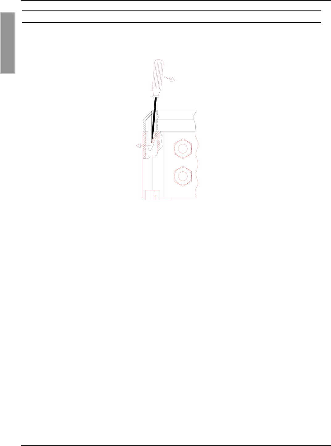
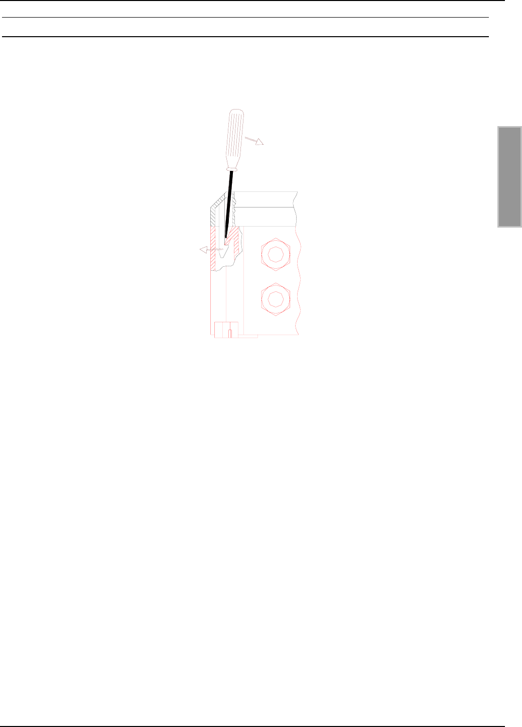
2.3.2 Öffnen des Deckels
In Bild 2-3: Öffnen des Deckels ist dargestellt wie sich das Gehäuse öffnen lässt.
Bild 2-3: Öffnen des Deckels
OBID i-scan®Montage ID ISC.LRU2000
FEIG ELECTRONIC GmbH Seite 11 von 56 M60801-0de-ID-B.doc
D E U T S C H
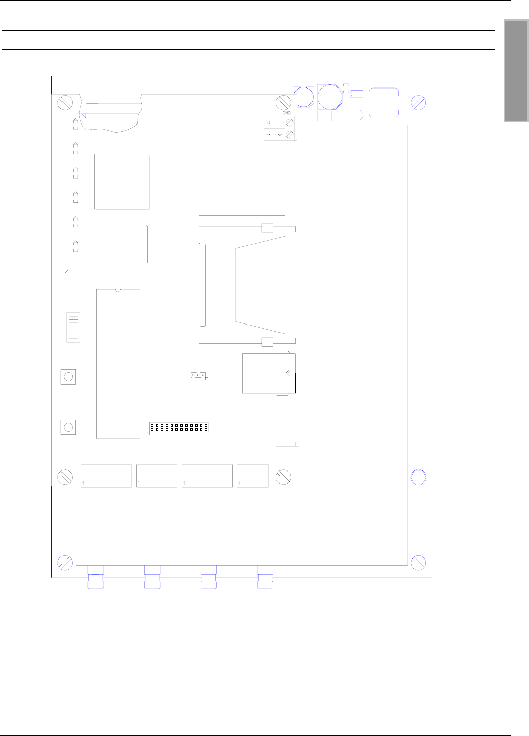
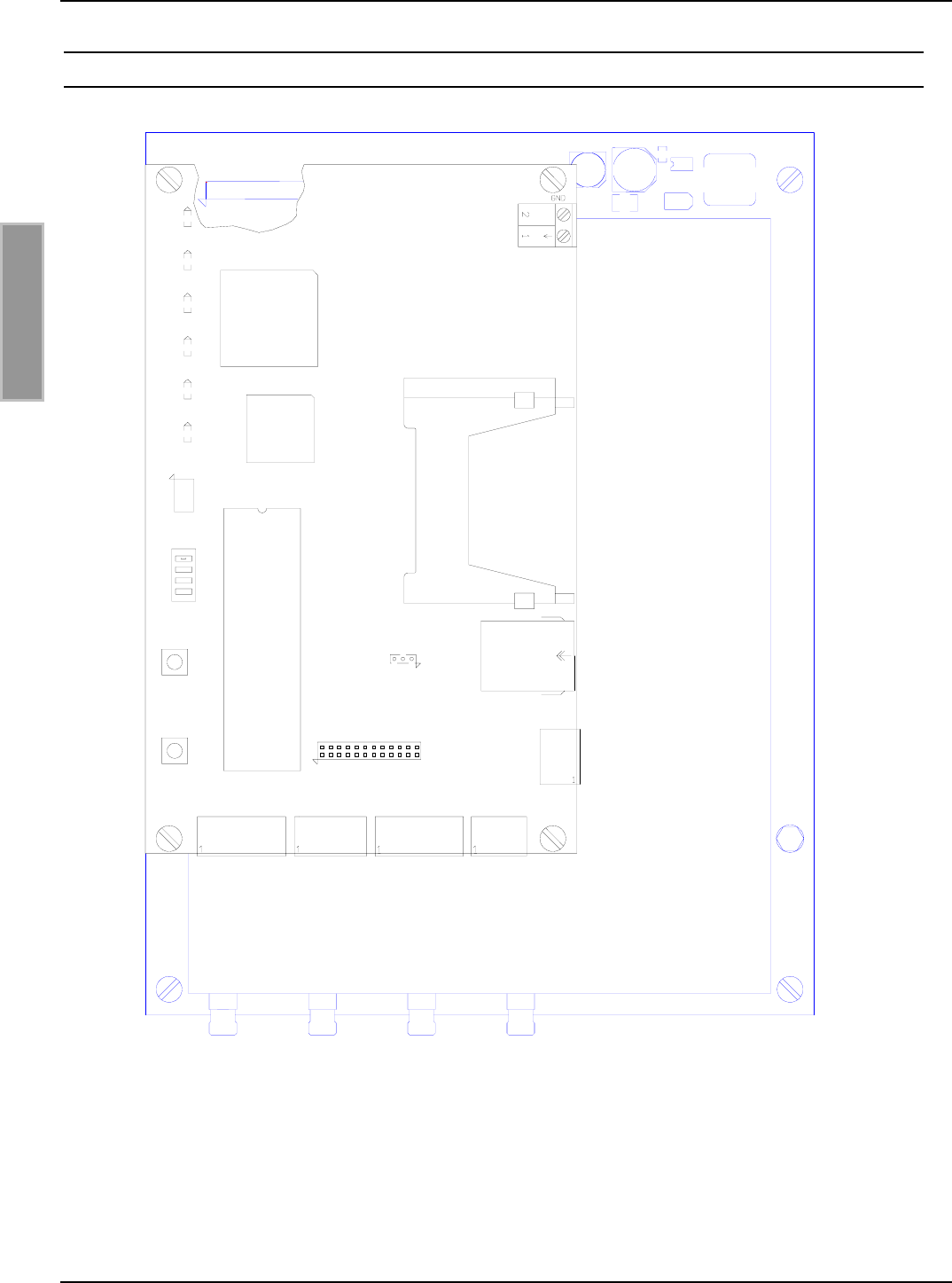
2.4 Anschlussklemmen
J1
J2
.
.
.
.
J12
V6
X14
T1
T2
S1
J20
X13
X11
X9
X5
GND
A-
B+
Y-
Z+
O-C
O-E
IN+
IN-
GND
A-
B+
Y-
Z+
GND
RxD
TxD
X12
ACC
X20
X1 X2 X3 X4
X6 X7 X8
V5
V4
V3
V2
V1
COM
NO
VDC
GND
Bild 2-4: Anschlussklemmen des Readers

OBID i-scan®Montage ID ISC.LRU2000
FEIG ELECTRONIC GmbH Seite 12 von 56 M60801-0de-ID-B.doc
D E U T S C H
2.5 Antennenanschluss
Der Anschluss der externen Antennen befindet sich auf der analogen Leiterplatte.
Das maximale Anzugsdrehmoment der SMA-Buchsen beträgt 0,45 Nm.
Achtung:
Höhere Anzugsdrehmomente führen zur Zerstörung des Steckers.
Klemme Beschreibung
X1, X2
X3, X4
Anschluss der externen Antennen
(Eingangsimpedanz 50Ω)
Tabelle 2-4: Anschluss der externen Antenne
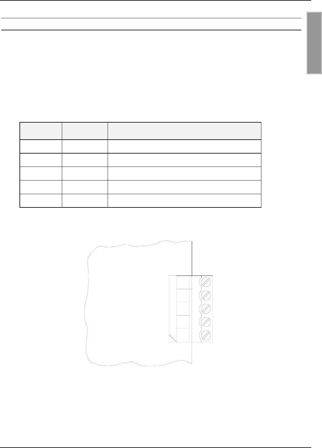
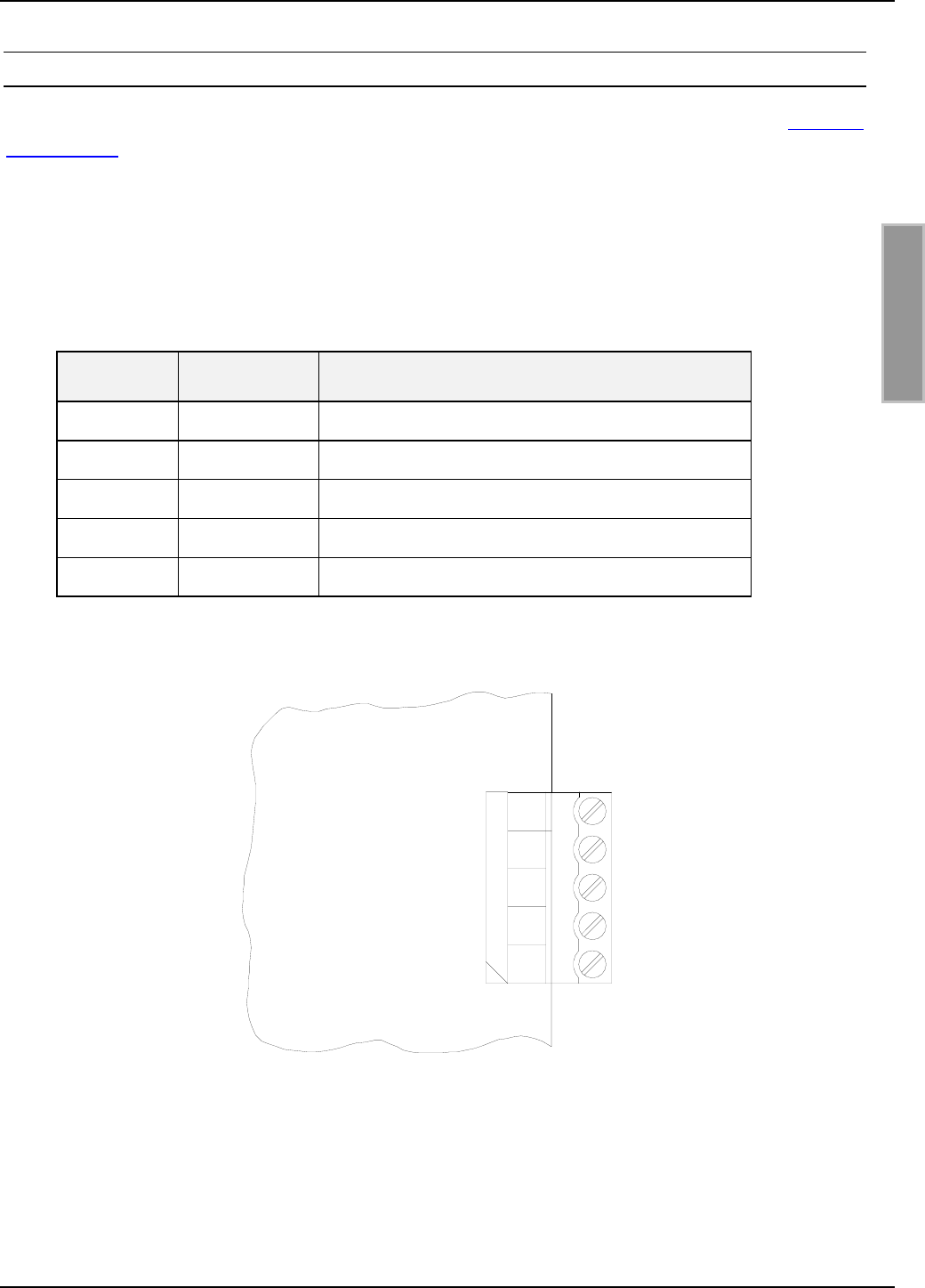
2.6 Versorgungsspannung
Die Versorgungsspannung von 15 bis 24 VDC ist an der Klemme X13 anzuschließen.
Klemme Kurzzeichen Beschreibung
X13 / Pin 1 VDC Vcc - Versorgungsspannung
X13 / Pin 2 GND Ground – Versorgungsspannung
Tabelle 2-5: Pinbelegung Versorgungsspannung
X13
GND
VDC
21
Bild 2-5: Anschluss der Versorgungsspannung
Hinweis:
• Eine Verpolung der Versorgungsspannung kann zur Zerstörung des Gerätes führen.
OBID i-scan®Montage ID ISC.LRU2000
FEIG ELECTRONIC GmbH Seite 13 von 56 M60801-0de-ID-B.doc
D E U T S C H
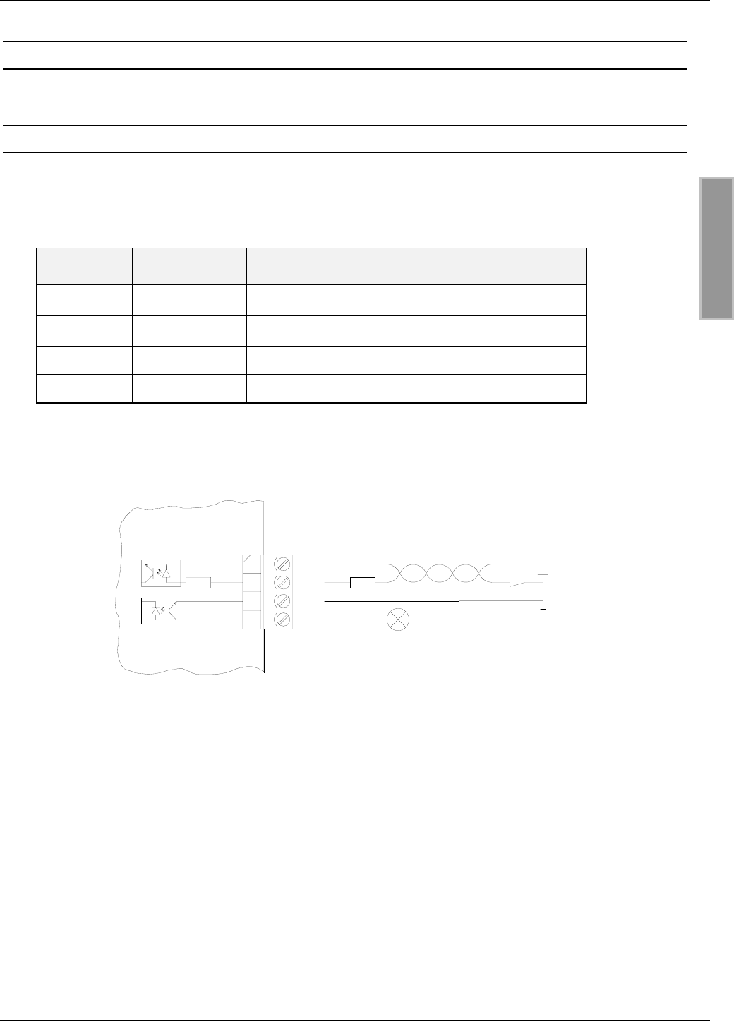
2.7 Eingänge / Ausgänge
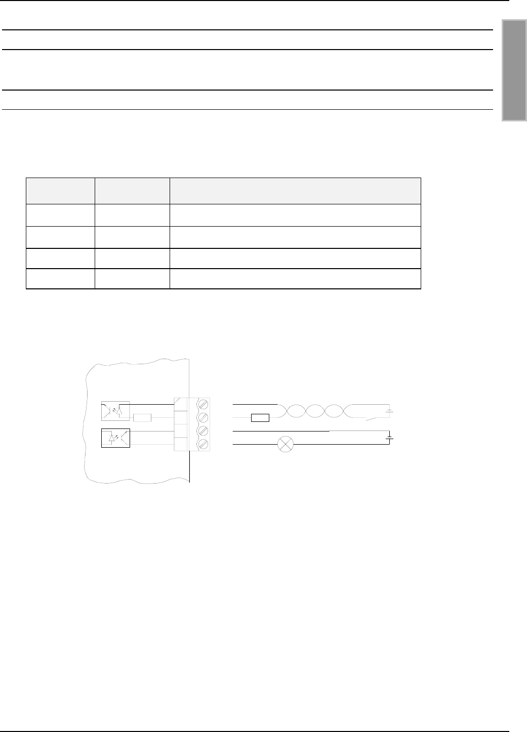
2.7.1 Optokoppler
Die Optokoppler an Klemmleiste X6 sind galvanisch von der Reader-Elektronik getrennt und müs-
sen daher mit einer externen Spannung versorgt werden.
Klemme Kurzzeichen Beschreibung
1O-C
Kollektor – Ausgang 1
2O-E
Emitter – Ausgang 1
3 IN+ + Eingang 1
4 IN- - Eingang 1
Tabelle 2-6: Pinbelegung Optokoppler
2
1
3
4
X6
Uext.
IN+
IN-
Rext
Rint
O-C
O-E Uext.
Bild 2-6: Interne und mögliche externe Beschaltung der Optokoppler

OBID i-scan®Montage ID ISC.LRU2000
FEIG ELECTRONIC GmbH Seite 14 von 56 M60801-0de-ID-B.doc
D E U T S C H
Optokopplerausgang (X6/1-2):
Der Transistoranschluß, Kollektor und Emitter, des Optokopplerausgangs ist von der Reader-
Elektronik galvanisch getrennt und ohne interne Zusatzbeschaltung an Klemme X6 nach außen
geführt. Der Ausgang muß daher mit einer externen Spannung betrieben werden.
Hinweise:
• Der Ausgang ist für max. 24 V DC / 30 mA ausgelegt.
• Verpolung oder Überlastung des Ausgangs führt zu dessen Zerstörung.
• Der Ausgang ist nur zum Schalten ohmscher Lasten vorgesehen.
Optokopplereingang (X6/3-4):
Die Eingangs-LED des Optokopplers ist intern mit einem Serienwiderstand von 500 Ω beschaltet.
Bei Versorgungsspannungen größer 10V muss der Eingangsstrom durch einen weiteren externen
Vorwiderstand (siehe Tabelle 2-7) auf max. 20 mA begrenzt werden.
Tabelle 2-7 zeigt die benötigten externen Vorwiderstande bei den verschiedenen externen Span-
nungen Uext.
Externe Spannung Uext Benötigter externer
Vorwiderstand Rext
5 V ... 10 V ---
11 V ... 15 V 270 Ω
16 V ... 20 V 560 Ω
21 V ... 24 V 820 Ω
Tabelle 2-7: Benötigter externer Vorwiderstand Rext
Hinweise:
• Der Eingang ist für eine maximale Eingangsspannung von 24 V DC und einem Ein-
gangsstrom von maximal 20 mA ausgelegt.
• Verpolung oder Überlastung des Eingangs führt zu dessen Zerstörung.
OBID i-scan®Montage ID ISC.LRU2000
FEIG ELECTRONIC GmbH Seite 15 von 56 M60801-0de-ID-B.doc
D E U T S C H
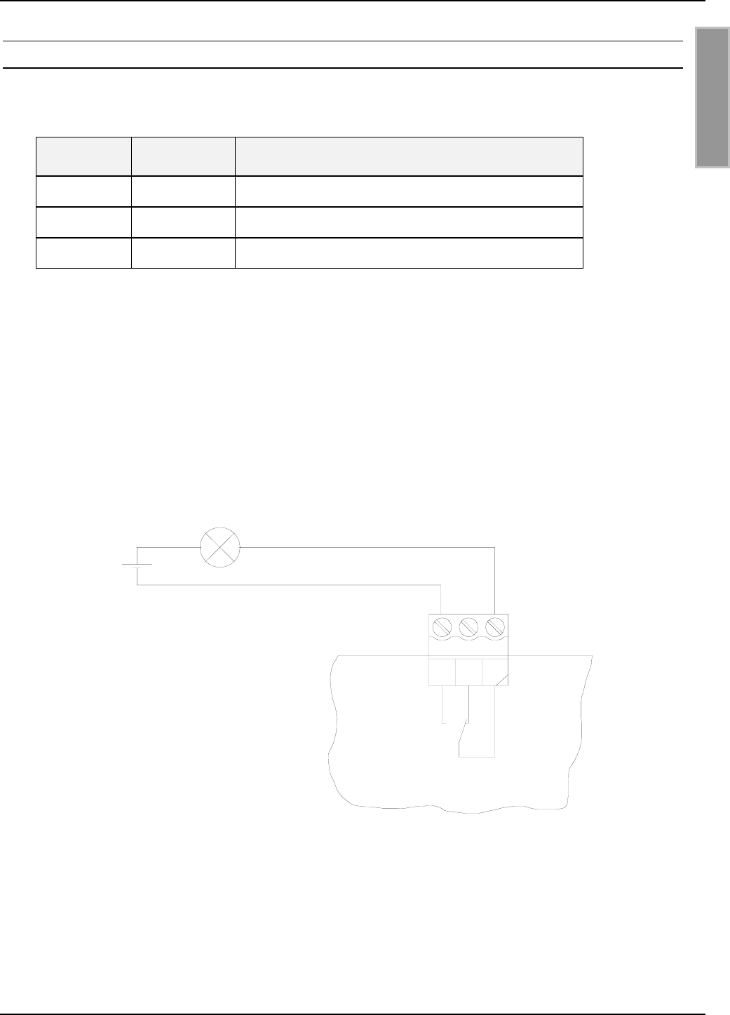
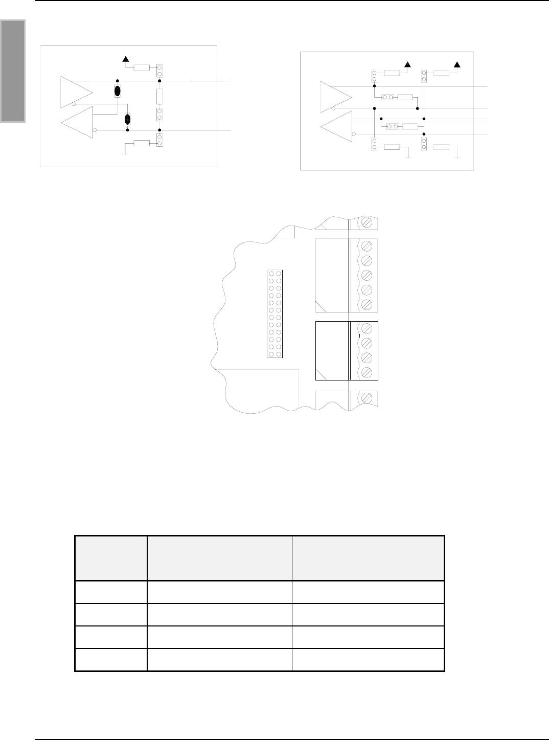
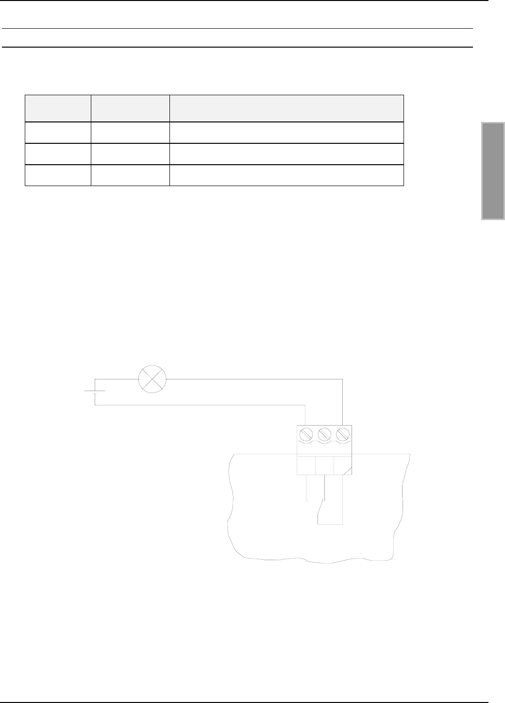
2.7.2 Relais
Als Relaisausgang steht ein Wechsler zur Verfügung.
Klemme Kurzzeichen Beschreibung
1 COM Arbeitskontakt
2 NC Öffner
3 NO Schließer
Tabelle 2-8: Pinbelegung Relaisausgang
Hinweise:
• Der Relaisausgang ist für max. 24 V DC / 2 A ausgelegt.
• Der Relaisausgang ist nur zum Schalten ohmscher Lasten vorgesehen. Im Falle einer
induktiven Last sind die Relaiskontakte durch eine externe Schutzbeschaltung zu schüt-
zen.
ext.
U
12
3
X9
COM
NO
NC
Bild 2-7: Interne und mögliche externe Beschaltung des Relaisausgangs
OBID i-scan®Montage ID ISC.LRU2000
FEIG ELECTRONIC GmbH Seite 16 von 56 M60801-0de-ID-B.doc
D E U T S C H
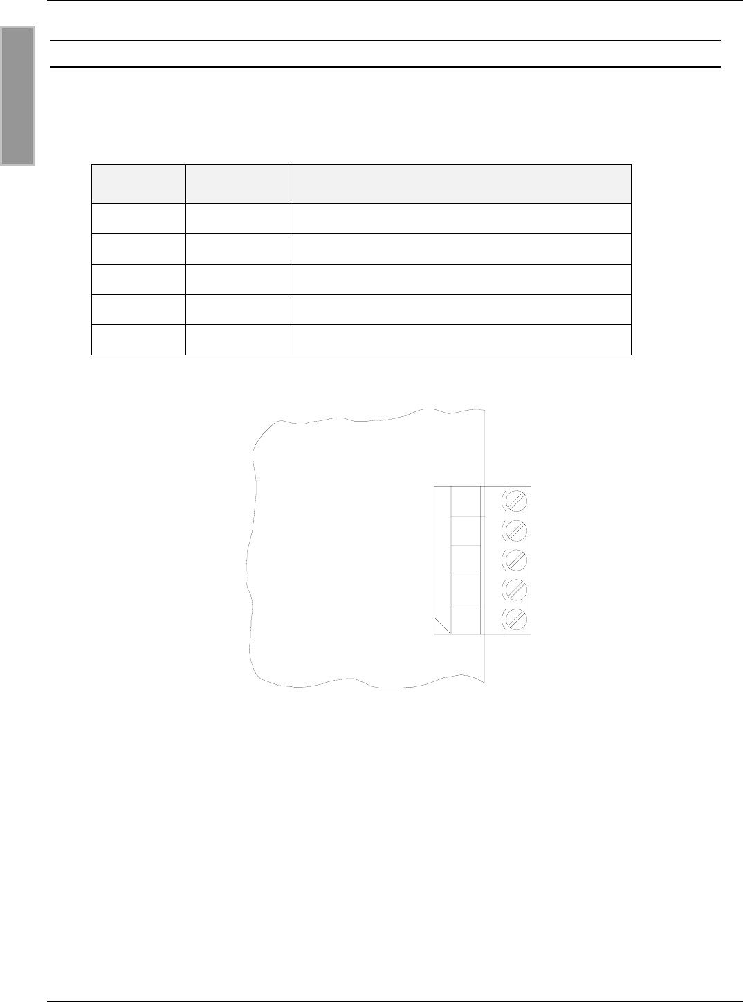
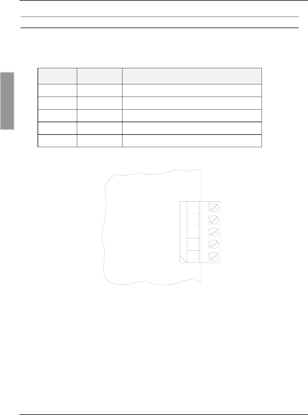
2.7.3 Readersynchronisation
Mit der Readersynchronisation können verschiedene Aktionen der Reader synchronisiert werden.
Klemme Kurzzeichen Beschreibung
1GNDGND
2 A- - Eingang
3 B+ + Eingang
4 Y- - Ausgang
5 Z+ +Ausgang
Tabelle 2-9: Pinbelegung Readersynchronisation
1
2
3
4
5
OUT+ (Z+)
OUT- (Y-)
IN+ (B+)
IN- (A-)
GND
X5
Bild 2-8: Eingang und Ausgang der Synchronisation
OBID i-scan®Montage ID ISC.LRU2000
FEIG ELECTRONIC GmbH Seite 17 von 56 M60801-0de-ID-B.doc
D E U T S C H
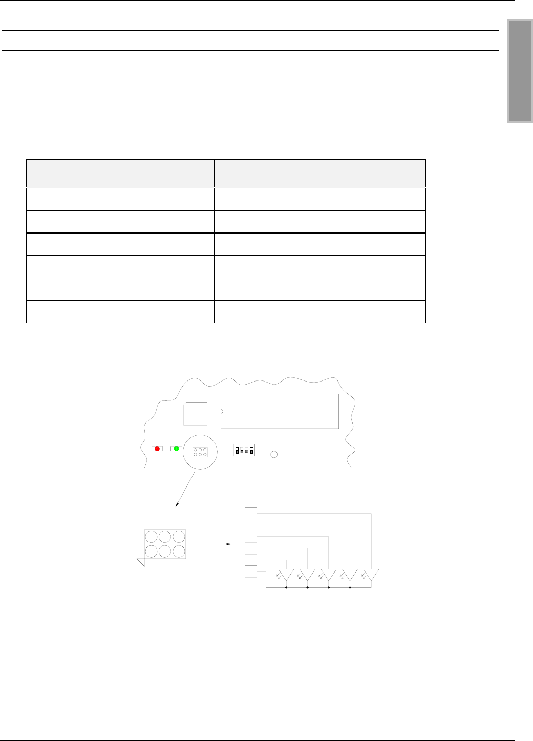
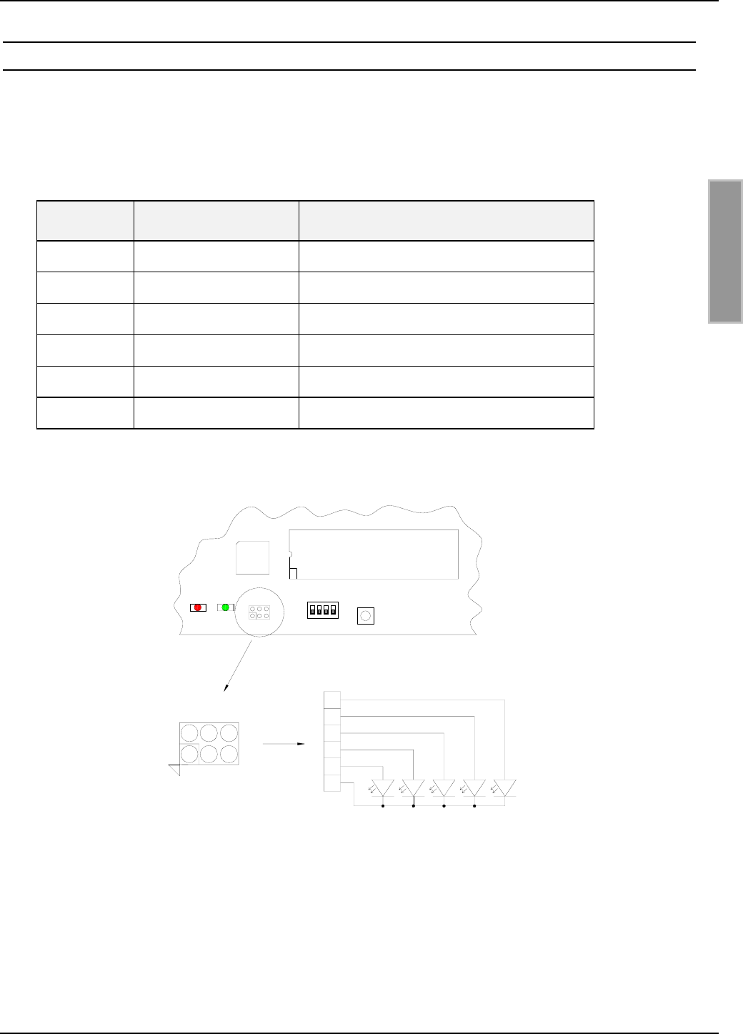
2.8 Anschluss externer Diagnose-LEDs
X14 ermöglicht den Anschluss zusätzlicher externer LEDs parallel zu den internen Diagnose-
LEDs.
Der Anschluss der externen LEDs erfolgt gemäß Bild 2-9.
Klemme Kurzzeichen Beschreibung
1V1 Anode ext. Funktion entspricht interner LED V1
2V2 Anode ext. Funktion entspricht interner LED V2
3V3 Anode ext. Funktion entspricht interner LED V3
4V4 Anode ext. Funktion entspricht interner LED V4
5V5 Anode ext. Funktion entspricht interner LED V5
6GND Gemeinsamer GND-Anschluss
Tabelle 2-10: Pinbelegung externe LEDs
135
642
6
5
4
3
2
1
V1V2V3V4V5
Externe LEDs
ACC-Modul
X14
V5 V6 S1 T1
X14
X14
Bild 2-9 Anschluss externer LEDs an X14
Hinweis:
• Die Ausgänge an X14 sind nur zum Schalten einer externen LED vorgesehen. Überlas-
tung der Ausgänge durch andere Lasten kann zu deren Zerstörung führen.

OBID i-scan®Montage ID ISC.LRU2000
FEIG ELECTRONIC GmbH Seite 18 von 56 M60801-0de-ID-B.doc
D E U T S C H
2.9 Schnittstellen
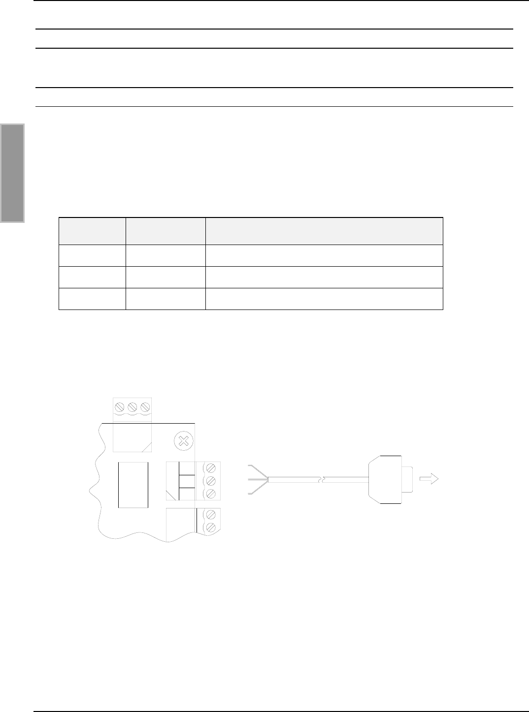
2.9.1 RS232-Schnittstelle
Der Anschluss der RS232-Schnittstelle erfolgt über X8.
Die Übertragungsparameter können per Softwareprotokoll konfiguriert werden.
Anschlussbelegung X8 (RS232-Schnittstelle):
Klemme Kurzzeichen Beschreibung
1 GND RS232 – GND
2 RxD RS232 - RxD
3 TxD RS232 - TxD
Tabelle 2-11: Pinbelegung RS232-Schnittstelle
PC
<−>
<−>
<−>
X8 / 3 Pin 2
X8 / 2 Pin 3
X8 / 1 Pin 5
9-pol. D-SUB-Buchse
X8
TxD
RxD
GND
3
2
1
Bild 2-10: Verdrahtungsbeispiel für den Anschluss der RS232-Schnittstelle
OBID i-scan®Montage ID ISC.LRU2000
FEIG ELECTRONIC GmbH Seite 19 von 56 M60801-0de-ID-B.doc
D E U T S C H
2.9.2 RS485/RS422 Schnittstelle
Die zweite asynchrone Schnittstelle kann als RS485 oder RS422 konfiguriert werden (siehe Ab-
schnitt 4.1: Schnittstellenkonfiguration mittels Jumper).
Der Anschluss der RS4xx-Schnittstelle erfolgt über X7.
Anschlussbelegung X7 (RS485/RS422-Schnittstelle):
Klemme Kurzzeichen Beschreibung
1 GND RS485/RS422 – GND
2 A- RS485/RS422 – (A -)
3 B+ RS485/RS422 – (B +)
4 Y- RS422 – (Y -)
5 Z+ RS422 – (Z +)
Tabelle 2-12: Pinbelegung RS485/RS422-Schnittstelle
RS422 (Z+)
RS422 (Y-)
5
RS485/RS422 (A-)
RS485/RS422 GND
RS485/RS422 (B+)
1
2
4
3
X7
Bild 2-11: Anschlussbelegung der RS485/RS422-Schnittstelle

OBID i-scan®Montage ID ISC.LRU2000
FEIG ELECTRONIC GmbH Seite 20 von 56 M60801-0de-ID-B.doc
D E U T S C H
2.9.3 Netzwerkanschluss
2.9.3.1 LAN (nur Gerätevarianten mit ACC)
Der Reader verfügt über einen Integrierten 10/100Tbase Netzwerkschnittstelle mit RJ-45-
Anschluß. Der Anschluss erfolgt über X11.
Bei einer strukturierten Verkabelung sollte Kabel der Kategorie 5 verwendet werden. Dies garan-
tiert einen problemlosen Betrieb bei 10Mbps oder 100Mbps.
Anschlussbelegung X8 (Netzwerk-Schnittstelle):
Klemme Kurzzeichen Beschreibung
1 TX+ Transmit Data +
2 TX- Transmit Data -
3 RX+ Receive Data +
4 VETH+ n.c.
5 VETH+ n.c.
6 RX- Receive Data -
7 VETH- n.c.
8 VETH- n.c.
Tabelle 2-13: Pinbelegung Ethernet-Schnittstelle
2.9.4 CompactFlash-Steckplatz (nur Gerätevarianten mit ACC)
Der Reader verfügt über einen CF2-Steckplatz (Stecker X12). Dieser Steckplatz für zukünftige
Erweiterungsmöglichkeiten durch CompactFlash-Karten vorgesehen.

OBID i-scan®Montage ID ISC.LRU2000
FEIG ELECTRONIC GmbH Seite 21 von 56 M60801-0de-ID-B.doc
D E U T S C H
3 Bedien- und Anzeigeelemente
3.1 LEDs
Tabelle 3-1 zeigt die Konfiguration der LED.
Kurzzeichen Beschreibung
LED V1 (grün) "RUN-LED 1"
- Signalisiert den ordnungsgemäßen Ablauf der
internen Reader-Software (DSP)
LED V2 (blau) Diagnose 1: RF-Kommunikation / EEPROM-Status
- Signalisiert durch ein kurzes Blinken die fehlerfreie Kommuni-
kation mit einem Transponder auf der RF-Schnittstelle
- Blinkt abwechselnd mit V1 nach dem Reset im Anschluss an
ein Software-Update
- Blinkt abwechselnd mit V1 falls nach einem Reset ein Daten-
fehler beim Lesen der Parameter auftrat
LED V3 (gelb) Diagnose 2: Host-Kommunikation
- Signalisiert durch ein kurzes Blinken das Senden eines Proto-
kolls an den Host auf der RS232/RS485-Schnittstelle
LED V4 (gelb) Reserviert
LED V5 (rot) Diagnose 4: RF-Warnung
- Leuchtet während der Reader-Initialisierung nach dem Ein-
schalten bzw. nach einem Reset.
- Leuchtet bei einem Fehler im RF-Teil des Readers. Der Feh-
lertyp kann per Software über die RS232/RS485-Schnittstelle
ausgelesen werden
LED V6 (grün)
(nur Gerätevari-
anten mit ACC)
"RUN-LED 2"
- Signalisiert den ordnungsgemäßen Ablauf des
Controllers
Tabelle 3-1: Konfiguration der LED

OBID i-scan®Montage ID ISC.LRU2000
FEIG ELECTRONIC GmbH Seite 22 von 56 M60801-0de-ID-B.doc
D E U T S C H
3.2 Taster / Schalter
Kurzzeichen Beschreibung
T1 Reset-Taster RF Controller
T2 Reset-Taster ACC
S1 Reserviert
Tabelle 3-2: Taster / Schalter
- T1: Durch betätigen von T1 wird am RF-Controller ein Reset durchgeführt
- T2: Durch betätigen von T2 wird am ACC ein Reset durchgeführt

OBID i-scan®Montage ID ISC.LRU2000
FEIG ELECTRONIC GmbH Seite 23 von 56 M60801-0de-ID-B.doc
D E U T S C H
4 Inbetriebnahme
4.1 Schnittstellenkonfiguration
4.1.1 RS485/RS422
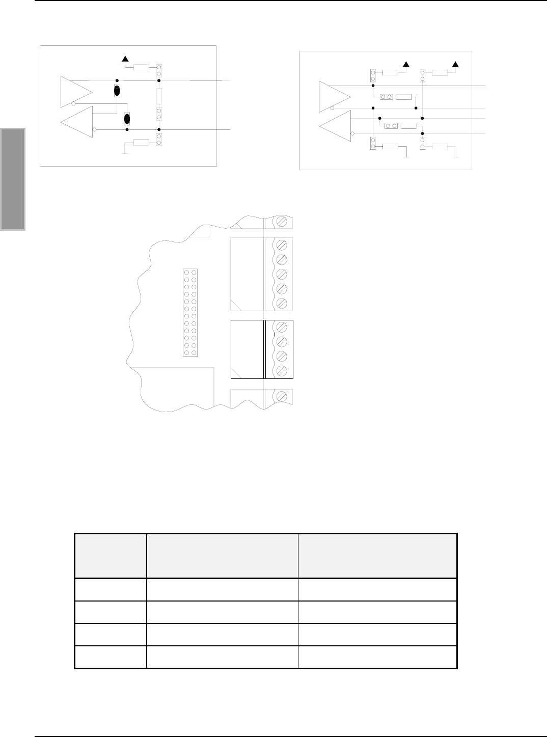
Über die Jumper J7 – J8 kann die asynchrone Schnittstelle als RS485- oder RS422-Schnittstelle
konfiguriert werden.
Jumper RS485 RS422
J7 Geschlossen offen
J8 Geschlossen offen
Tabelle 4-1: Konfiguration der RS485/RS422-Schnitstelle
Es können die eventuell benötigten Abschlusswiderstände mit den Jumpern J1 bis J6 zugeschaltet
werden.
Jumper Geschlossen offen
J1 Pull-Up an RS4xx - B ohne Pull-Up an RS4xx - B
J2 Pull-Down an RS4xx - A ohne Pull-Down an RS4xx – A
J5 Abschlusswiderstand
RS4xx - A ⇔ RS4xx - B
ohne Abschlusswiderstand
RS485 - A ⇔ RS485 - B
J3 Pull-Up an RS422 - Z ohne Pull-Up an RS422 - Z
J4 Pull-Down an RS422 - Y ohne Pull-Down an RS422 – Y
J6 Abschlusswiderstand
RS422 - Y ⇔ RS422 - Z
ohne Abschlusswiderstand
RS422 - Y ⇔ RS422 - Z
Tabelle 4-2: Abschlusswiderstände der RS485/RS422
OBID i-scan®Montage ID ISC.LRU2000
FEIG ELECTRONIC GmbH Seite 24 von 56 M60801-0de-ID-B.doc
D E U T S C H
RS485 +
J1
J5
J2
500 Ohm
500 Ohm
120 Ohm
J7
J8
RS485 -
RS422 Y-
RS422 B+
500
500 500
120
120
J2
J3 J1
J6
J5
RS422 Z+
J4 500
RS422 A-
Bild 4-1: Jumper der RS485-Schnittstelle Bild 4-2: Jumper der RS422-Schnittstelle
J12
J11
J10
J9
J8
J7
J6
J5
J4
J3
J2
J1 X6
X7
Bild 4-3: Jumper der RS485/RS422-Schnittstelle
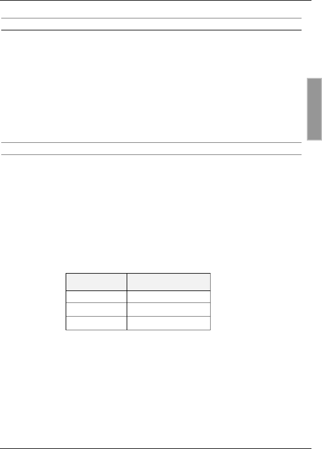
Tabelle 4-3 zeigt die Standardkonfiguration der Jumper J9 bis J12. Diese sind für die RS485 und
RS422 identisch.
Jumper LRU2000
Gerätevarianten mit ACC
LRU2000
Gerätevarianten ohne ACC
J9 Geschlossen offen
J10 Geschlossen Geschlossen
J11 offen offen
J12 offen Geschlossen
Tabelle 4-3: Standardkonfiguration der RS485/RS422

OBID i-scan®Montage ID ISC.LRU2000
FEIG ELECTRONIC GmbH Seite 25 von 56 M60801-0de-ID-B.doc
D E U T S C H
4.1.1.1 Adresseinstellung RS485/RS422x für Busbetrieb
Für den Busbetrieb bietet der Reader die Möglichkeit die benötigte Busadresse per Software zu
vergeben.
Die Adressvergabe erfolgt über den Host-Rechner. Mit Hilfe der Software können dem Reader die
Adressen "0" bis "254" zugewiesen werden.
Hinweis:
Da alle Reader werksseitig die Adresse 0 eingestellt haben, müssen sie nacheinander ange-
schlossen und konfiguriert werden.
4.1.2 Netzwerkanschluss - LAN
Vorraussetzung für den Einsatz des TCP/IP-Protokolls ist, dass jedes Gerät am Netzwerk über
eine eigene IP-Adresse verfügt. Alle Reader verfügen über eine werksseitig voreingestellte IP-
Adresse.
Die Reader müssen nacheinander ans Netzwerk angeschlossen und konfiguriert werden.
Tabelle 4-4 zeigt die Standardkonfiguration des Netzwerkanschlusses.
Netzwerk Adresse
IP-Adresse 192.168.10.10
Subnet-Mask 255.255.255.0
Port 10001
Tabelle 4-4: Standardkonfiguration des Netzwerkanschlusses

OBID i-scan®Montage ID ISC.LRU2000
FEIG ELECTRONIC GmbH Seite 26 von 56 M60801-0de-ID-B.doc
D E U T S C H
5 Funkzulassungen
5.1 Europa (CE)
Die Funkanlage entspricht, bei bestimmungsgemäßer Verwendung den grundlegenden Anforde-
rungen des Artikels 3 und den übrigen einschlägigen Bestimmungen der R&TTE Richtlinie
1999/5/E6 vom März 99.
Bei Betrieb im Band b2 nach ERC/REC 70-03 Annex 11 (865,6MHz – 867,6MHz) gelten folgende
Einschränkungen für (Stand: Juli 2006):
Österreich, Belgien, Bulgarien, Kroatien, Zypern, Est-
land, Frankreich, Griechenland, Ungarn, Irland, Italien,
Letland, Lichtenstein, Litauen, Luxemburg, Norwegen,
Portugal, Rumänien, Slovakische Republik, Slovenien,
Spanien, Schweden, Niederlande, Türkei, Großbritan-
nien
Frequenzbereich nicht implementiert
Estland Individuelle Lizenz benötigt
Bei Betrieb im Band I nach ERC/REC 70-03 Annex 1 (869,400MHz – 869,650MHz) gelten folgen-
de Einschränkungen für (Stand: Juli 2006):
Bulgarien Frequenzbereich nicht implementiert
Italien max 25 mW e.r.p.
Slovakische Republik max 10 mW e.r.p.
5.2 USA (FCC)
FCC ID: PJMLRU2000
This device complies with Part 15 of the FCC Rules. Operation is subject to the following
two conditions:
(1) this device may not cause harmful interference, and
(2) this device must accept any interference received, including interference that may
cause undesired operation.
Unauthorized modifications may void the authority granted under Federal communica-
tions Commission Rules permitting the operation of this device.

OBID i-scan®Montage ID ISC.LRU2000
FEIG ELECTRONIC GmbH Seite 27 von 56 M60801-0de-ID-B.doc
D E U T S C H
6 Technische Daten
Mechanische Daten
• Gehäuse Kunststoffgehäuse mit Kühlblech
• Abmessungen ( B x H x T ) 180 x 320 x 110 mm
• Gewicht 2,0 kg
• Schutzart IP 54
• Farbe RAL 9011
Elektrische Daten
• Spannungsversorgung 15 V DC bis 24 V DC ± 5 %
Noise Ripple : max. 150 mV
• Leistungsaufnahme max. 30 VA
• Betriebsfrequenz 869,525 MHz (EN 300 220)
865,6 – 867,6MHz (EN 302 208)
902-928MHz (FCC CFR 47 Part 15.247)
• Sendeleistung 100 mW – 3 W (100 mW Step – Software)
4 W EIRP (FCC CFR 47 Part 15.247)
2 W ERP (EN 302 208)
0,5Watt ERP (EN 300 220)
• Modulationsgrad 20% - 40% und 100%
(per Software einstellbar)
• Empfänger Datenraten 40 – 320 kbps
• Antennenanschlüsse
– 4 x gemultiplext 4 x SMA Buchse (50Ω)
• Ausgänge:
- 1 Optokoppler
- 1 Differenzausgang
- 1 Relais ( 1 x Wechsler)
24 V DC / 30 mA (galvanisch getrennt)
Reader Synchronisation
24 V DC / 2 A

OBID i-scan®Montage ID ISC.LRU2000
FEIG ELECTRONIC GmbH Seite 28 von 56 M60801-0de-ID-B.doc
D E U T S C H
• Eingänge
- 1 Optokoppler
- 1 Differenzeingang
max. 24 V DC/ 20 mA
Reader Synchronisation
• Schnittstellen - RS232
- RS485 / RS422 (wahlweise einstellbar)
- Ethernet (TCP/IP) (Nur Gerätevariante mit ACC)
• Protokoll Modi - FEIG ISO Host
- Buffer Reader Mode (Data Filtering and buffe-
ring)
• Unterstützte Transponder - 18000-6-B
- EPC class 1 gen 1
- EPC class 1 gen 2
• Signalgeber optisch 6 LEDs zur Diagnose des Betriebszustandes
Umgebungsbedingungen
• Temperaturbereich
- Betrieb
- Lagerung
-25°C bis +55°C (-25°C bis +70°C)
-25°C bis +85°C
• Vibration EN60068-2-6
10 Hz bis 150 Hz : 0,075 mm / 1 g
• Schock EN60068-2-27
Beschleunigung : 30 g
Angewendete Normen
• Zulassung Funk
- Europa
- USA
EN 302 208
EN 300 220
FCC 47 CFR Part 15
• EMV EN 301 489
• Sicherheit
- Niederspannung
- Human Exposure
EN 60950
EN 50364

OBID i-scan®Installation ID ISC.LRU2000
FEIG ELECTRONIC GmbH Page 30 of 56 M60801-0de-ID-B.doc
E N G L I S H
Note
© Copyright 2004 - 2006 by
FEIG ELECTRONIC GmbH
Lange Strasse 4
D-35781 Weilburg-Waldhausen
Tel.: +49 6471 3109-0
http://www.feig.de
With the edition of this document, all previous editions become void. Indications made in this manual may be
changed without previous notice.
Copying of this document, and giving it to others and the use or communication of the contents thereof are
forbidden without express authority. Offenders are liable to the payment of damages. All rights are reserved
in the event of the grant of a patent or the registration of a utility model or design.
Composition of the information in this manual has been done to the best of our knowledge. FEIG
ELECTRONIC GmbH does not guarantee the correctness and completeness of the details given in this
manual and may not be held liable for damages ensuing from incorrect or incomplete information. Since,
despite all our efforts, errors may not be completely avoided, we are always grateful for your useful tips.
The instructions given in this manual are based on advantageous boundary conditions. FEIG ELECTRONIC
GmbH does not give any guarantee promise for perfect function in cross environments and does not give
any guaranty for the functionality of the complete system which incorporates the subject of this document.
FEIG ELECTRONIC call explicit attention that devices which are subject of this document are not designed
with components and testing methods for a level of reliability suitable for use in or in connection with surgical
implants or as critical components in any life support systems whose failure to perform can reasonably be
expected to cause significant injury to a human. To avoid damage, injury, or death, the user or application
designer must take reasonably prudent steps to protect against system failures.
Use Exclusion in Transportation Market: Devices which are subject of this document may NOT be sold,
used, leased, offer for sale, or otherwise transferred, exported, and imported by anyone in the Transportation
Market. “Transportation Market” means (i) Electronic Toll and Traffic Management (ETTM), (ii) Public Sector
Vehicle Registration, Inspection and Licensing Programs, (iii) Railroad Locomotive and Wagon tracking, (iv)
airport based ground transportation management systems (GTMS) and taxi dispatch, (v) revenue based
parking, and (vi) vehicle initiated mobile payment applications, where the RFID sticker/tag is initially attached
to the vehicle but not incorporated at the point of vehicle manufacture.
FEIG ELECTRONIC GmbH assumes no responsibility for the use of any information contained in this
manual and makes no representation that they free of patent infringement. FEIG ELECTRONIC GmbH does
not convey any license under its patent rights nor the rights of others.
OBID® and OBID i-scan® are registered trademarks of FEIG ELECTRONIC GmbH.

OBID i-scan®Installation ID ISC.LRU2000
FEIG ELECTRONIC GmbH Page 31 of 56 M60801-0de-ID-B.doc
E N G L I S H
Contents
1 Safety Instructions / Warning - Read before start-up ! 33
2 Performance Features of Reader Family ID ISC.LRU2000 34
2.1 Performance features..................................................................................................34
2.2 Available Reader types...............................................................................................34
2.3 Installation ...................................................................................................................35
2.3.1 Cable glands .................................................................................................................36
2.3.2 Opening the cover .........................................................................................................37
2.4 Terminals .....................................................................................................................38
2.5 Antenna connection....................................................................................................39
2.6 Supply voltage.............................................................................................................40
2.7 Inputs / Outputs...........................................................................................................41
2.7.1 Optocouplers .................................................................................................................41
2.7.2 Relay .............................................................................................................................43
2.7.3 Reader synchronization.................................................................................................44
2.8 External diagnostic LED connections.......................................................................45
2.9 Interfaces .....................................................................................................................46
2.9.1 RS232 interface.............................................................................................................46
2.9.2 RS485/RS422 interface.................................................................................................47
2.9.3 Network connection.......................................................................................................48
2.9.4 CompactFlash Slot (only device version with ACC) ...................................................48
3 Operating and Display Elements 49
3.1 LEDs .............................................................................................................................49
3.2 Buttons / Switches ......................................................................................................50
4Startup 51
4.1 Interface configuration................................................................................................51
4.1.1 RS485/RS422 ...............................................................................................................51

OBID i-scan®Installation ID ISC.LRU2000
FEIG ELECTRONIC GmbH Page 32 of 56 M60801-0de-ID-B.doc
E N G L I S H
4.1.2 Network connection - LAN.............................................................................................53
5 Radio Approvals 54
5.1 Europe (CE)..................................................................................................................54
5.2 USA (FCC)....................................................................................................................54
6 Technical Data 55

OBID i-scan®Installation ID ISC.LRU2000
FEIG ELECTRONIC GmbH Page 33 of 56 M60801-0de-ID-B.doc
E N G L I S H
1 Safety Instructions / Warning - Read before start-up !
• The device may only be used for the purpose intended by the manufacturer
• When installing the device in areas covered under FCC 47 CFR Part 15 a minimum separation
of 23cm between antenna and the human body must be maintained.
• The operation manual should be kept readily available at all times for each user.
• Unauthorized changes and the use of spare parts and additional devices which have not been
sold or recommended by the manufacturer may cause fire, electric shocks or injuries. Such
unauthorized measures shall exclude the manufacturer from any liability.
• The liability-prescriptions of the manufacturer in the issue valid at the time of purchase are valid
for the device. The manufacturer shall not be held legally responsible for inaccuracies, errors,
or omissions in the manual or automatically set parameters for a device or for an incorrect
application of a device.
• Repairs may only be undertaken by the manufacturer.
• Installation, operation, and maintenance procedures should only be carried out by qualified
personnel.
• Use of the device and its installation must be in accordance with national legal requirements
and local electrical codes .
• When working on devices the valid safety regulations must be observed.
• Special advice for wearers of cardiac pacemakers:
Although this device doesn't exceed the valid limits for electromagnetic fields you should keep
a minimum distance of 25 cm between the device and your cardiac pacemaker and not stay in
the immediate proximity of the device’s antenna for any length of time.

OBID i-scan®Installation ID ISC.LRU2000
FEIG ELECTRONIC GmbH Page 34 of 56 M60801-0de-ID-B.doc
E N G L I S H
2 Performance Features of Reader Family ID ISC.LRU2000
2.1 Performance features
The Reader has been developed for reading passive data carriers, so-called „Smart Labels“, using
an operating frequency in the UHF range.
2.2 Available Reader types
The following Readers are currently available:
Reader type Description
ID ISC.LRU2000-A-EU Device version with ACC for Europe
ID ISC.LRU2000-A-FCC Device version with ACC for USA
ID ISC.LRU2000i-A-EU Device version with ACC and internal antenna for Europe
ID ISC.LRU2000i-A-FCC Device version with ACC and internal antenna for USA
Table 2-1 Reader types
Reader module type Description
ID ISC.LRMU2000-B-EU Module version without ACC for Europe
ID ISC.LRMU2000-B-FCC Module version without ACC for USA
Table 2-2 Reader module types
OBID i-scan®Installation ID ISC.LRU2000
FEIG ELECTRONIC GmbH Page 35 of 56 M60801-0de-ID-B.doc
E N G L I S H
2.3 Installation
The Reader is designed for wall-mount, including outdoors. Holes for mounting on a wall are
provided in the housing.
Fig. 2-1 Installation drawing
316
300.5
161
180
90
OBID i-scan®Installation ID ISC.LRU2000
FEIG ELECTRONIC GmbH Page 36 of 56 M60801-0de-ID-B.doc
E N G L I S H
2.3.1 Cable glands
The cable glands are located on the underside of the housing. Fig. 2-2: Installation drawing shows
the arrangement, and Table 2-3: Cable glands for ID ISC.LRU2000 indicates which cable glands
should be used for the individual lines.
21 3
9
5
8
4
67
Fig. 2-2 Installation drawing
Cable gland Size Clamping
range
[mm] Description
1 M 16 4.5 – 10 Antenna cable
2 M 16 4.5 – 10 Antenna cable
3 M 16 4.5 – 10 Antenna cable
4 M 16 4.5 – 10 Antenna cable
5 M 12 3.5 – 7 Supply voltage
6 M 16 4.5 – 10 In-/Outputs/Interface
7 M 16 4.5 – 10 In-/Outputs/Interface
8 M 12 3.5 – 7 In-/Outputs/Interface
9 M 25 9 – 17 Network connection (optional)
Table 2-3: Cable glands for ID ISC.LRU2000
OBID i-scan®Installation ID ISC.LRU2000
FEIG ELECTRONIC GmbH Page 37 of 56 M60801-0de-ID-B.doc
E N G L I S H
2.3.2 Opening the cover
Fig. 2-3 Opening the cover shows how to open up the housing.
Fig. 2-3: Opening the cover
OBID i-scan®Installation ID ISC.LRU2000
FEIG ELECTRONIC GmbH Page 38 of 56 M60801-0de-ID-B.doc
E N G L I S H
2.4 Terminals
J1
J2
.
.
.
.
J12
V6
X14
T1
T2
S1
J20
X13
X11
X9
X5
GND
A-
B+
Y-
Z+
O-C
O-E
IN+
IN-
GND
A-
B+
Y-
Z+
GND
RxD
TxD
X12
ACC
X20
X1 X2 X3 X4
X6 X7 X8
V5
V4
V3
V2
V1
COM
NO
VDC
GND
Fig. 2-4: Reader terminals

OBID i-scan®Installation ID ISC.LRU2000
FEIG ELECTRONIC GmbH Page 39 of 56 M60801-0de-ID-B.doc
E N G L I S H
2.5 Antenna connection
The external antenna is connected on the analog circuit board.
The maximum tightening torque for the SMA sockets is 0.45 Nm.
Caution:
Exceeding the tightening torque will destroy the plug.
Terminal Description
X1, X2
X3, X4
Connection for external antennas
(input impedance 50Ω)
Table 2-4: External antenna connection

OBID i-scan®Installation ID ISC.LRU2000
FEIG ELECTRONIC GmbH Page 40 of 56 M60801-0de-ID-B.doc
E N G L I S H
2.6 Supply voltage
The supply voltage of 15 to 24 VDC is connected to Terminal X13.
Terminal Abbreviation Description
X13 / Pin 1 VDC Vcc – supply voltage
X13 / Pin 2 GND Ground – supply voltage
Table 2-5: Pin-outs for supply voltage
X13
GND
VDC
21
Fig. 2-5 Connecting the supply voltage
Note:
• Reversing the supply voltage polarity may destroy the device.
OBID i-scan®Installation ID ISC.LRU2000
FEIG ELECTRONIC GmbH Page 41 of 56 M60801-0de-ID-B.doc
E N G L I S H
2.7 Inputs / Outputs
2.7.1 Optocouplers
The optocouplers on Terminal X6 are galvanically isolated from the Reader electronics and must
therefore be externally supplied.
Terminal Abbreviation Description
1O-C
Collector – Output 1
2O-E
Emitter – Output 1
3 IN+ + Input 1
4 IN- - Input 1
Table 2-6: Optocoupler pin-outs
2
1
3
4
X6
Uext.
IN+
IN-
Rext
Rint
O-C
O-E Uext.
Fig. 2-6: Internal and possible external wiring of the optocouplers

OBID i-scan®Installation ID ISC.LRU2000
FEIG ELECTRONIC GmbH Page 42 of 56 M60801-0de-ID-B.doc
E N G L I S H
Optocoupler output (X6/1-2):
The transistor connections, collector and emitter, of the optocoupler output are galvanically isolated
from the Reader electronics and are carried to the outside without any internal ancillary circuitry on
Terminal X6. The output must therefore be powered by an external power supply.
Note:
• The output is configured for max. 24 V DC / 30 mA.
• Polarity reversal or overload on the output will destroy it.
• The output is intended for switching resistive loads only.
Optocoupler input (X6/3-4):
The input LED associated with the optocoupler is connected internally to a series resistor of 500 Ω.
For supply voltages of greater than 10V the input current must be limited to max. 20 mA by means
of an additional series resistor (see Table 2-7).
Table 2-7 shows the necessary external resistors for various external voltages Uext.
External voltage Uext Required external series
resistor Rext
5 V ... 10 V ---
11 V ... 15 V 270 Ω
16 V ... 20 V 560 Ω
21 V ... 24 V 820 Ω
Table 2-7: Required external series resistor Rext
Notes:
• The input is configured for a maximum input voltage of 24 V DC and an input current of
max. 20 mA.
• Polarity reversal or overload on the input will destroy it.
OBID i-scan®Installation ID ISC.LRU2000
FEIG ELECTRONIC GmbH Page 43 of 56 M60801-0de-ID-B.doc
E N G L I S H
2.7.2 Relay
A relay output is provided in the form of a changeover relay.
Terminal Abbreviation Description
1 COM Working contact
2 NC Normally closed
3 NO Normally open
Table 2-8: Relay output pin-outs
Notes:
• The relay output is configured for max. 24 V DC / 2 A.
• The relay output is intended for switching resistive loads only. If an inductive load is
connected, the relay contacts must be protected by means of an external protection
circuit.
ext.
U
12
3
X9
COM
NO
NC
Fig. 2-7: Internal and possible external wiring of the relay output
OBID i-scan®Installation ID ISC.LRU2000
FEIG ELECTRONIC GmbH Page 44 of 56 M60801-0de-ID-B.doc
E N G L I S H
2.7.3 Reader synchronization
Reader synchronization can be used to synchronize various Reader actions.
Terminal Abbreviation Description
1GNDGND
2 A- - Input
3 B+ + Input
4 Y- - Output
5 Z+ + Output
Table 2-9: Reader synchronization pin-outs
1
2
3
4
5
OUT+ (Z+)
OUT- (Y-)
IN+ (B+)
IN- (A-)
GND
X5
Fig. 2-8: Synchronization input and output
OBID i-scan®Installation ID ISC.LRU2000
FEIG ELECTRONIC GmbH Page 45 of 56 M60801-0de-ID-B.doc
E N G L I S H
2.8 External diagnostic LED connections
X14 allows for connection of additional external LEDs in parallel with the internal diagnostic LEDs.
The external LEDs are connected as shown in Fig. 2-9.
Terminal Abbreviation Description
1V1 Anode ext. Function same as internal LED V1
2V2 Anode ext. Function same as internal LED V2
3V3 Anode ext. Function same as internal LED V3
4V4 Anode ext. Function same as internal LED V4
5V5 Anode ext. Function same as internal LED V5
6GND Common GND
Table 2-10: External LED pin-outs
V4 V3 V2 V1
1
2
3
X14
31 5
4
X14
26
V5 V6 X14 S1 T1
ACC-Modul
external LEDs
V5
6
4
5
Fig. 2-9: Connecting external LEDs to X14
Note:
• The outputs on X14 are intended for switching an external LED only. Overloading the
outputs with other loads may destroy them.
OBID i-scan®Installation ID ISC.LRU2000
FEIG ELECTRONIC GmbH Page 46 of 56 M60801-0de-ID-B.doc
E N G L I S H
2.9 Interfaces
2.9.1 RS232 interface
The RS232 interface is connected on X8.
The transmission parameters can be configured by means of software protocol.
Pin configuration X8 (RS232 interface):
Terminal Abbreviation Description
1 GND RS232 – GND
2 RxD RS232 - RxD
3 TxD RS232 - TxD
Table 2-11: RS232 interface pin-outs
X8 / 3
X8 / 2
X8 / 1
Pin 2
<−>
Pin 5
Pin 3
<−>
<−>
9-pol. D-SUB-Jack
1
2
3
X8
TxD
RxD
GND PC
Fig. 2-10: Wiring example for connecting the RS232 interface
OBID i-scan®Installation ID ISC.LRU2000
FEIG ELECTRONIC GmbH Page 47 of 56 M60801-0de-ID-B.doc
E N G L I S H
2.9.2 RS485/RS422 interface
The second asynchronous interface can be configured for RS485 or RS422 (see Section Interface
configuration).
The RS485/RS422 interface is connected on X7.
Pin configuration X7 (RS485/RS422 interface):
Terminal Abbreviation Description
1 GND RS485/RS422 – GND
2 A- RS485/RS422 – (A -)
3 B+ RS485/RS422 – (B +)
4 Y- RS422 – (Y -)
5 Z+ RS422 – (Z +)
Table 2-12: RS485/RS422 interface pin-outs
RS422 (Z+)
RS422 (Y-)
5
RS485/RS422 (A-)
RS485/RS422 GND
RS485/RS422 (B+)
1
2
4
3
X7
Fig. 2-11: Wiring example for the RS485/RS422 interface

OBID i-scan®Installation ID ISC.LRU2000
FEIG ELECTRONIC GmbH Page 48 of 56 M60801-0de-ID-B.doc
E N G L I S H
2.9.3 Network connection
2.9.3.1 LAN (only device versions with ACC)
The Reader has an integrated 10/100Tbase network port for an RJ45. Connection is made on X11.
With structured cabling Cat 5 cables should be used. This ensure reliable operation at 10Mbps or
100Mbps.
Pin configuration for X8 (network interface):
Terminal Abbreviation Description
1 TX+ Transmit Data +
2 TX- Transmit Data -
3 RX+ Receive Data +
4 VETH+ n.c.
5 VETH+ n.c.
6 RX- Receive Data -
7 VETH- n.c.
8 VETH- n.c.
Table 2-13: Ethernet interface pin-outs
2.9.4 CompactFlash Slot (only device version with ACC)
The Reader has a CF2 slot (connector X12). This slot is for future use by CompactFlash cards.

OBID i-scan®Installation ID ISC.LRU2000
FEIG ELECTRONIC GmbH Page 49 of 56 M60801-0de-ID-B.doc
E N G L I S H
3 Operating and Display Elements
3.1 LEDs
Table 3-1 shows the LED configuration.
Abbreviation Description
LED V1 (green) "RUN-LED 1"
- Indicates proper running of the internal Reader software (DSP)
LED V2 (blue) Diagnostic 1: RF communication / EEPROM status
- Short flashing indicates errorless communication with a
transponder on the RF interface
- Flashes alternately with V1 after a reset following a software
update
- Flashes alternately with V1 in case of a data error when
reading the parameters after a reset
LED V3 (yellow) Diagnostic 2: Host communication
- Short flashing indicates sending of a protocol to the host on the
RS232/RS485 interface
LED V4 (yellow) Reserved
LED V5 (red) Diagnostic 4: RF warning
- Comes on during Reader initialization after power-on or after a
reset.
- Comes on when there is an error in the RF section of the
Reader. The error type can be read out via software over the
RS232/RS485 interface
LED V6 (green)
(only device
version with ACC)
"RUN-LED 2"
- Indicates proper running of the AC Controller
Table 3-1: LED configuration

OBID i-scan®Installation ID ISC.LRU2000
FEIG ELECTRONIC GmbH Page 50 of 56 M60801-0de-ID-B.doc
E N G L I S H
3.2 Buttons / Switches
Abbreviation Description
T1 RF Controller reset button
T2 ACC reset button
S1 Reserved
Table 3-2: Buttons / Switches
- T1: Pressing T1 resets the RF Controller
- T2: Pressing T2 resets the ACC

OBID i-scan®Installation ID ISC.LRU2000
FEIG ELECTRONIC GmbH Page 51 of 56 M60801-0de-ID-B.doc
E N G L I S H
4 Startup
4.1 Interface configuration
4.1.1 RS485/RS422
Jumpers J7 – J8 are used to configure the asynchronous interface as an RS485 or R422 port.
Jumper RS485 RS422
J7 closed open
J8 closed open
Table 4-1: Configuration of the RS485/RS422 port
Any termination resistors needed can be enabled using jumpers J1 through J6.
Jumper Closed Open
J1 Pull-Up on RS4xx - B without Pull-Up on RS4xx - B
J2 Pull-Down on RS4xx - A without Pull-Down on RS4xx – A
J5 Termination resistor
RS4xx - A ⇔ RS4xx - B
without Termination resistor
RS485 - A ⇔ RS485 - B
J3 Pull-Up on RS422 - Z without Pull-Up on RS422 - Z
J4 Pull-Down on RS422 - Y without Pull-Down on RS422 –
Y
J6 Termination resistor
RS422 - Y ⇔ RS422 - Z
without Termination resistor
RS422 - Y ⇔ RS422 - Z
Table 4-2: Termination resistors for RS485/RS422
OBID i-scan®Installation ID ISC.LRU2000
FEIG ELECTRONIC GmbH Page 52 of 56 M60801-0de-ID-B.doc
E N G L I S H
RS485 +
J1
J5
J2
500 Ohm
500 Ohm
120 Ohm
J7
J8
RS485 -
RS422 Y-
RS422 B+
500
500 500
120
120
J2
J3 J1
J6
J5
RS422 Z+
J4 500
RS422 A-
Fig. 4-1: RS485 interface jumpers Fig. 4-2: RS422 interface jumpers
J12
J11
J10
J9
J8
J7
J6
J5
J4
J3
J2
J1 X6
X7
Fig. 4-3: RS485/RS422 interface jumpers
shows the standard configuration of jumpers J9 through J12. These are identical for RS485 and
RS422.
Jumper LRU2000
device version with ACC
LRU2000
device version without ACC
J9 closed open
J10 closed closed
J11 open open
J12 open closed
Table 4-3: Standard configuration for RS485/RS422
OBID i-scan®Installation ID ISC.LRU2000
FEIG ELECTRONIC GmbH Page 53 of 56 M60801-0de-ID-B.doc
E N G L I S H
4.1.1.1 Address assignment of RS485/RS422 for bus operation
For bus operation the Reader can be assigned the required bus address via software.
The address is assigned by the host computer. The software is used to assign addresses “0”
through “254” to the Reader.
Note:
Since all Readers are factory set with address „0“, they must be connected and configured
one after the other.
4.1.2 Network connection - LAN
The prerequisite for using TCP/IP protocol is that each device has a unique address on the
network. All Readers have a factory set IP address.
The Readers must be connected and configured one after the other.
Table 4-4: shows the standard configuration of the network connection.
Network Address
IP address 192.168.10.10
Subnet mask 255.255.255.0
Port 10001
Table 4-4: Standard configuration of the network connection

OBID i-scan®Installation ID ISC.LRU2000
FEIG ELECTRONIC GmbH Page 54 of 56 M60801-0de-ID-B.doc
E N G L I S H
5 Radio Approvals
5.1 Europe (CE)
When used according to regulation, this radio equipment conforms with the basic requirements of
Article 3 and the other relevant provisions of the R&TTE Guideline 1999/E6 dated March 99.
Restrictions for operating the ID ISC.LRU2000 (Effective: July 2006):
When operating the ID ISC.LRU2000 in Band b2 ERC/REC 70-03 Annex 11 (865,6MHz –
867,6MHz) the following restrictions apply:
Austria, Belgium, Bulgaria, Croatia, Cyprus, France,
Greece, Hungary, Ireland, Italy, Latvia, Lichtenstein,
Lithuania, Luxembourg, Norway, Portugal, Romania,
Slovak Republic, Slovenia, Spain, Sweden, The Neth-
erlands, Turkey, United Kingdom
Operation not currently permitted
Estonia Operation only with individual license
When operating the ID ISC.LRU2000 in Band I ERC/REC 70-03 Annex 1 (869,400MHz –
869,650MHz) the following restrictions apply:
Bulgaria Operation not currently permitted
Italy max 25 mW e.r.p.
Slovak Republic max 10 mW e.r.p.
5.2 USA (FCC)
FCC ID: PJMLRU2000
This device complies with Part 15 of the FCC Rules. Operation is subject to the following
two conditions:
(1) this device may not cause harmful interference, and
(2) this device must accept any interference received, including interference that may
cause undesired operation.
Unauthorized modifications may void the authority granted under Federal communica-
tions Commission Rules permitting the operation of this device.

OBID i-scan®Installation ID ISC.LRU2000
FEIG ELECTRONIC GmbH Page 55 of 56 M60801-0de-ID-B.doc
E N G L I S H
6 Technical Data
Mechanical Data
• Housing Plastic enclosure with cooling fin
• Dimensions ( W x H x D ) 180 x 320 x 110 mm
• Weight 2.0 kg
• Enclosure rating IP 54
• Color RAL 9011
Electrical Data
• Supply voltage 15 V DC to 24 V DC ± 5 %
Noise Ripple : max. 150 mV
• Power consumption max. 30 VA
• Operating frequency 869.525 MHz (EN 300 220)
865.6 – 867.6 MHz (EN 302 208)
902-928 MHz (FCC CFR 47 Part 15.247)
• Transmitting power 100 mW – 3 W (100 mW Step – Software)
4 W EIRP (FCC CFR 47 Part 15.247)
2 W ERP (EN 302 208)
0.5 W ERP (EN 300 220)
• Modulation 20% - 40% and 100%
(software configurable)
• Receiver Data rates 40 – 320 kbps
• Antenna connections
– 4 x multiplexing 4 x SMA socket (50Ω)
• Outputs:
- 1 optocoupler
- 1 differential output
- 1 relay ( 1 x changeover)
24 V DC / 30 mA (galvanically isolated)
Reader synchronization
24 V DC / 2 A
• Inputs
- 1 optocoupler
- 1 differential input
max. 24 V DC/ 20 mA
Reader synchronization

OBID i-scan®Installation ID ISC.LRU2000
FEIG ELECTRONIC GmbH Page 56 of 56 M60801-0de-ID-B.doc
E N G L I S H
• Interfaces - RS232
- RS485 / RS422 (selectable)
- Ethernet (TCP/IP) (only device version with
ACC)
• Protocol modes - FEIG ISO Host
- Buffer Reader Mode (Data Filtering and
buffering)
• Supported transponders - 18000-6-B
- EPC class 1 gen
- EPC class 1 gen 2
• Optical indicators 6 LEDs for operating status diagnostics
Ambient
• Temperature range
- Operating
- Storage
-25°C to +55°C (-25°C to +70°C)
-25°C to +85°C
• Vibration EN60068-2-6
10 Hz to 150 Hz :0.075 mm / 1 g
• Shock EN60068-2-27
Acceleration : 30 g
Applicable standards
• RF approval
- Europe
- USA
EN 302 208
EN 300 220
FCC 47 CFR Part 15
• EMC EN 301 489
• Safety
- Low-Voltage
- Human Exposure
EN 60950
EN 50364