Feig Electronic MR100-PR100 Passive Tag Reader User Manual Operation Manual
Feig Electronic GmbH Passive Tag Reader Operation Manual
Contents
- 1. Users Manual
- 2. Installation Guide
Users Manual
i-scan
M10202-2de-ID-B.DOC
OBID
Montageanleitung / Mounting Instruction
ID ISC.MR100-A /
ID ISC.PR100-A
(deutsch / english)

Identifikation System OBIDi-scan
Seite 2von 34 FEIG ELECTRONIC GmbH
D E U T S C H
deutsche Version ab Seite 3
english version from page 19
E N G L I S H

Montageanleitung ID ISC.MR100-A / ID ISC.PR100-A
FEIG ELECTRONIC GmbH Seite 3von 34
D E U T S C H
Ausgabe: cf/01/09/24 -m10202-2de-id-b.doc
© Copyright 2001 by FEIG ELECTRONIC GmbH
Weitergabe sowie Vervielfältigung dieses Dokuments, Verwertung und Mitteilung ihres Inhalts sind nicht gestat-
tet, soweit nicht ausdrücklich zugestanden. Zuwiderhandlung verpflichtet zu Schadenersatz. Alle Rechte für
den Fall der Patenterteilung oder Gebrauchsmuster-Eintragung vorbehalten.
Die Angaben in dieser Montageanleitung können ohne vorherige Ankündigung geändert werden. Alle früheren Ausga-
ben verlieren mit dieser Montageanleitung ihre Gültigkeit.
Die Zusammenstellung der Informationen in dieser Montageanleitung erfolgt nach bestem Wissen und Gewissen. FEIG
ELECTRONIC GmbH übernimmt keine Gewährleistung für die Richtigkeit und Vollständigkeit der gemachten Angaben.
Insbesondere kann FEIG ELECTRONIC GmbH nicht für Folgeschäden aufgrund fehlerhafter oder unvollständiger An-
gaben haftbar gemacht werden.
Die in diesem Handbuch gemachten Installationsempfehlungen gehen von günstigsten Rahmenbedingungen aus. FEIG
ELECTRONIC GmbH übernimmt keine Gewähr für die einwandfreie Funktion einer OBID®-Anlage in systemfremden
Umgebungen.
Da sich Fehler, trotz aller Bemühungen nie vollständig vermeiden lassen, sind wir für Hinweise jederzeit dankbar.
FEIG ELECTRONIC GmbH übernimmt keine Gewährleistung dafür, dass die in diesem Dokument enthaltenden Infor-
mationen frei von fremden Schutzrechten sind. FEIG ELECTRONIC GmbH erteilt mit diesem Dokument keine Lizenzen
auf eigene oder fremde Patente oder andere Schutzrechte.
OBID®ist ein eingetragenes Warenzeichen der FEIG ELECTRONIC GmbH

Identifikation System OBIDi-scan
Seite 4von 34 FEIG ELECTRONIC GmbH
D E U T S C H
Funkzulassungen
Europa (CE)
Die Funkanlage entspricht, bei bestimmungsgemäßer Verwendung den grundlegenden Anforde-
rungen des Artikels 3 und den übrigen einschlägigen Bestimmungen der R&TTE Richtlinie
1999/5/E6 vom März 99.
USA (FCC)
FCC ID: PJMMR100-PR100
This device complies with Part 15 of the FCC Rules. Operation is subject to the following
two conditions:
(1) this device may not cause harmful interference, and
(2) this device must accept any interference received, including interference that may
cause undesired operation.
Unauthorized modifications may void the authority granted under Federal communications
Commission Rules permitting the operation of this device.
ID ISC.MR100 :
Die Zulassung nach FCC 47 CFR CH. I Part 15 gilt im Zusammenhang mit der
Antenne ID ISC.ANT340/240A.

Montageanleitung ID ISC.MR100-A / ID ISC.PR100-A
FEIG ELECTRONIC GmbH Seite 5von 34
D E U T S C H
Inhalt
1. Sicherheits- und Warnhinweise ................................................................................ 6
2. Leistungsmerkmale der Reader................................................................................ 7
2.1 Leistungsmerkmale ........................................................................................................... 7
2.2 Verfügbare Readertypen.................................................................................................... 7
3. Montage und Anschluß.............................................................................................. 8
3.1 Spannungs- und Schnittstellenanschluß X2.................................................................... 8
3.2 Versorgungsspannung...................................................................................................... 9
3.3 Antennenanschluß X4 (nur ID ISC.MR100)..................................................................... 10
3.4 Asynchrone Schnittstelle ................................................................................................ 11
3.4.1 Schnittstellenkonfiguration mittels Jumper.................................................................. 11
3.4.2 RS232-Schnittstelle .................................................................................................... 12
3.4.3 RS485 Schnittstelle..................................................................................................... 13
3.4.4 Adresseinstellung für Busbetrieb................................................................................. 13
4. Bedien- und Anzeigeelemente................................................................................. 14
4.1 LED.................................................................................................................................... 14
5. Technische Daten..................................................................................................... 15
6. Anhang ...................................................................................................................... 17
6.1 Zubehör ............................................................................................................................ 17
6.1.1 Serielles Datenkabel ID CAB.RS-A............................................................................. 18
6.1.2 Netzteil ID NET.12VDC............................................................................................... 18

Identifikation System OBIDi-scan
Seite 6von 34 FEIG ELECTRONIC GmbH
D E U T S C H
1. Sicherheits- und Warnhinweise
Vor Inbetriebnahme unbedingt lesen !
•Das Gerät darf nur für den vom Hersteller vorgesehenen Zweck verwendet werden.
•Die Bedienungsanleitung ist zugriffsfähig aufzubewahren und jedem Benutzer auszuhändigen.
•Unzulässige Veränderungen und die Verwendung von Ersatzteilen und Zusatzeinrichtungen,
die nicht vom Hersteller des Gerätes verkauft oder empfohlen werden, können Brände, elektri-
sche Schläge und Verletzungen verursachen. Solche Maßnahmen führen daher zu einem Aus-
schluß der Haftung und der Hersteller übernimmt keine Gewährleistung.
•Für das Gerät gelten die Gewährleistungsbestimmungen des Herstellers in der zum Zeitpunkt
des Kaufs gültigen Fassung. Für eine ungeeignete, falsche manuelle oder automatische Ein-
stellung von Parametern für ein Gerät bzw. ungeeignete Verwendung eines Gerätes wird keine
Haftung übernommen.
•Reparaturen dürfen nur vom Hersteller durchgeführt werden.
•Anschluß-, Inbetriebnahme-, Wartungs-, Messungs- und Einstellungsarbeiten am Gerät dürfen
nur von Elektrofachkräften mit einschlägiger Unfallverhütungsausbildung erfolgen.
•Vor dem Öffnen des Gerätes ist stets die Versorgungsspannung abzuschalten und durch
Nachmessen sicherzustellen, daß das Gerät spannungslos ist.
•Das Verlöschen einer Betriebsanzeige ist kein Indikator dafür, daß das Gerät vom Netz ge-
trennt und spannungslos ist.
•Alle Arbeiten am Gerät und dessen Aufstellung müssen in Übereinstimmung mit den nationalen
Bestimmungen und den örtlichen Vorschriften durchgeführt werden.
•Der Benutzer ist dafür verantwortlich, daß das Gerät nach den anerkannten technischen Re-
geln im Aufstellungsland sowie anderen regionalen gültigen Vorschriften aufgestellt und ange-
schlossen wird. Dabei sind Kabeldimensionierung, Absicherung, Erdung, Abschaltung, Tren-
nung, Isolationsüberwachung und der Überstromschutz besonders zu berücksichtigen.

Montageanleitung ID ISC.MR100-A / ID ISC.PR100-A
FEIG ELECTRONIC GmbH Seite 7von 34
D E U T S C H
2. Leistungsmerkmale der Reader
2.1 Leistungsmerkmale
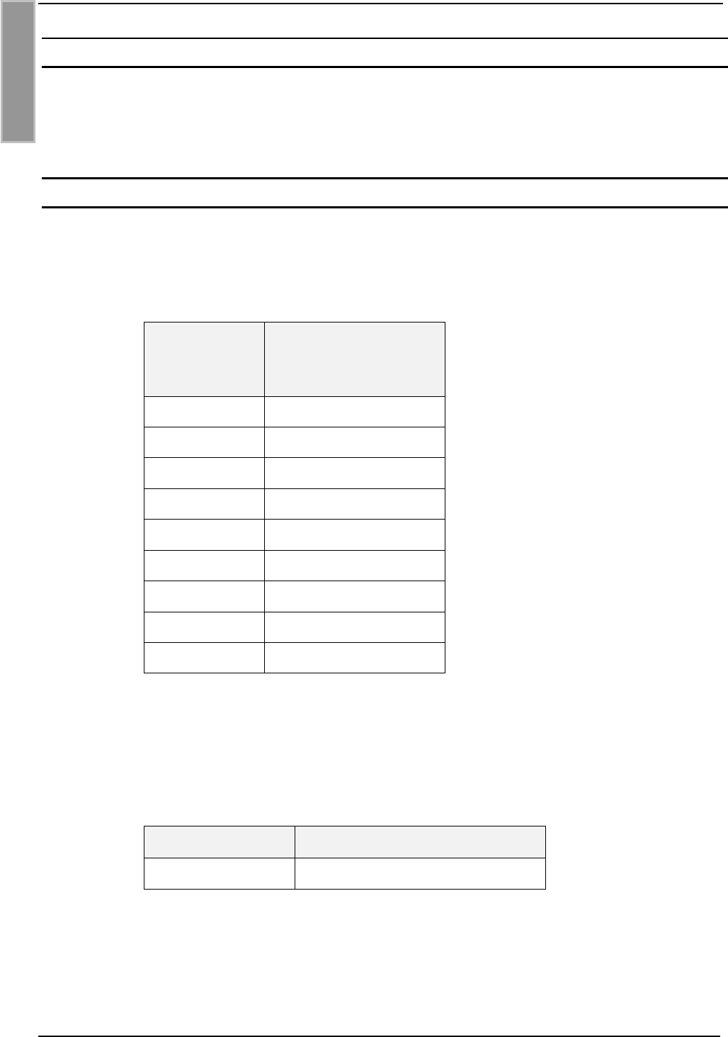
Der Reader ist für das Lesen von passiven Datenträgern, sogenannten „Smart Labels“, mit einer
Betriebsfrequenz von 13,56 MHz entwickelt worden.
Der ID ISC.MR100 eignet sich für alle Anwendungen, bei denen mittlere Lesereichweiten benötigt
werden. Zusätzlich wird noch eine externe Antenne benötigt, die an dem Reader angeschlossen
werden muß.
Der ID ISC.PR100 eignet sich für alle Anwendungen, bei denen keine großen Lesereichweiten
benötigt werden. Der Reader verfügt über eine interne Antenne, so daß keine externe Antenne
benötigt wird.
Eine Anticollision-Funktion ermöglicht das gleichzeitige Lesen von bis zu 30 Transpondern pro
Sekunde.
Die Elektronik des Readers ist in einem Kunststoffgehäuse untergebracht, welches die Schutzart
IP30 besitzt. Der Reader verfügt über eine asynchrone Schnittstelle, die wahlweise als RS232
oder RS485 konfiguriert werden kann.
Durch die Konfigurierbarkeit der Schnittstelle kann der Reader auch am Datenbus mit RS485
Schnittstelle betrieben werden. Die Adresse des Readers kann dabei per Software vorgegeben
werden.
2.2 Verfügbare Readertypen
Folgende Reader sind z.Z. verfügbar:
Readertyp Beschreibung
ID ISC.MR100-A Asynchrone Schnittstelle und externe Antenne
ID ISC.PR100-A Asynchrone Schnittstelle und interne Antenne
Identifikation System OBIDi-scan
Seite 8von 34 FEIG ELECTRONIC GmbH
D E U T S C H
3. Montage und Anschluß
Der Reader ist für die Büroumgebung konzipiert. Es ist eine Wandmontage möglich. Der Wand-
montagesatz ist zusätzlich zu bestellen. ( Siehe Anhang: 6.1 Zubehör).
3.1 Spannungs- und Schnittstellenanschluß X2
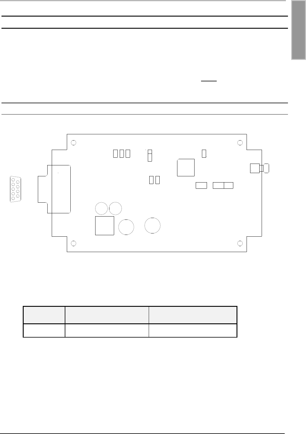
Zum Anschluß der Spannungsversorgung und der asynchronen Schnittstelle befindet sich auf der
Leiterplatte ein 9-poliger D-Subminiatur-Steckverbinder (Buchse). Siehe auch Abbildung 3-1: Lei-
terplatte mit Jumpern und Anschlußsteckern.
X2
Schnittstelle
+
Spgsversorgung
1n.c.
2A-
3B+
4n.c.
5GND
6n.c.
7AGND
8n.c.
9+12 V DC
Tabelle 3-1: Anschlußbelegung des Steckers X2
Für den Reader ist ein serielles Datenkabel mit integriertem Spannungsanschluß erhältlich.
(Siehe 6.1 Zubehör und 6.1.1 Serielles Datenkabel ID CAB.RS-A).
Feig Artikel Nr. Bezeichnung
1690.000.00.00 ID CAB.RS-A
Tabelle 3-2: Serielles Datenkabel
Montageanleitung ID ISC.MR100-A / ID ISC.PR100-A
FEIG ELECTRONIC GmbH Seite 9von 34
D E U T S C H
3.2 Versorgungsspannung
Die Versorgungsspannung von 12 V DC ist an der Klemme X2 der Leiterplatte anzuschließen.
Hinweis:
Eine Verpolung der Versorgungsspannung kann zur Zerstörung des Gerätes führen.
Klemme Kurzzeichen Beschreibung
X2 / Pin 9 +12V + 12 V DC – Versorgungsspannung
X2 / Pin 7 AGND Ground – Versorgungsspannung
Tabelle 3-3: Anschluß der Versorgungsspannung
Netzteilempfehlungen :
Zur Ausnutzung der vollständigen Leistungsfähigkeit des Reader-Moduls sollte auf eine ausrei-
chend stabilisierte und rauschfreie Spannungsversorgung geachtet werden. Bevorzugt wird ein
lineares Netzteil mit 12V DC / 580 mA. Bei der Verwendung eines Schaltnetzteils ist darauf zu
achten, daß die interne Schaltfrequenz des Netzteils unterhalb von 300 kHz liegt.
(Siehe: 6.1 Zubehör und 6.1.2 Netzteil ID NET.12VDC).
Feig Artikel Nr. Bezeichnung
1688.000.00.00 ID NET.12VDC
Tabelle 3-4: Empfohlenes Netzteil

Identifikation System OBIDi-scan
Seite 10 von 34 FEIG ELECTRONIC GmbH
D E U T S C H
3.3 Antennenanschluß X4 (nur ID ISC.MR100)
Zum Anschluß der externen Antenne befindet sich auf der Leiterplatte eine SMA-Buchse.
Das maximale Anzugsdrehmoment der SMA-Buchsen beträgt 0,45 Nm.
(Achtung: Höhere Anzugsdrehmomente führen zur Zerstörung des Steckers.)
Klemme Beschreibung
X4 Anschluß der externen Antenne
(Eingangsimpedanz 50Ω)
Tabelle 3-5: Anschluß der externen Antenne
Hinweise:
•Die Eingangsimpedanz der Antenne ist auf einen Wert von 50 Ω±(3 Ω∠3°) abzugleichen.
•Die optimale Betriebsgüte der Antenne sollte im Bereich QB= 10...20 liegen. Zur Ermitt-
lung der Betriebsgüte muß die Antenne mit einer 50Ω-Quelle, z.B. einem Network Analy-
zer oder einem Frequenzgenerator, versorgt werden.
•Für das Erreichen optimaler Lesereichweiten sollte die Länge der Antennenzuleitungen
3,6 m ±0,1 m betragen.
•Beim Anschluß einer Antenne ist darauf zu achten, daß diese die zulässigen Grenzwerte
der nationalen Vorschriften bezüglich Funkanlagen nicht überschreitet.
Installation mit FCC Zulassung:
In Länden,in denen eine FCC-Zulassung benötigt wird, darf der Reader nur mit den in Tabelle
3-6aufgeführten Antennen in Betrieb genommen werden. Aufgrund von Änderungen oder Modifi-
zierungen, die nicht ausdrücklich von der zuständigen Zulassungsbehörde genehmigt wurden,
kann die Betriebserlaubnis des Anwenders erlöschen.
Artikel Nr. Bezeichnung
1663.000.00.00 ID ISC.ANT340/240
Tabelle 3-6: Antennen mit FCC Zulassung
Die Anschluß-, Inbetriebnahme-, Wartungs-, Messungs- und Einstellungsarbeiten am Gerät
dürfen nur von Elektrofachkräften oder Personen mit äquivalenter Ausbildung erfolgen.
Montageanleitung ID ISC.MR100-A / ID ISC.PR100-A
FEIG ELECTRONIC GmbH Seite 11 von 34
D E U T S C H
3.4 Asynchrone Schnittstelle
Die asynchrone Schnittstelle kann wahlweise als RS485 oder RS232 konfiguriert werden.
Hinweis:
Der gleichzeitige Betrieb von RS232 und RS485 Schnittstelle ist nicht möglich.
3.4.1 Schnittstellenkonfiguration mittels Jumper
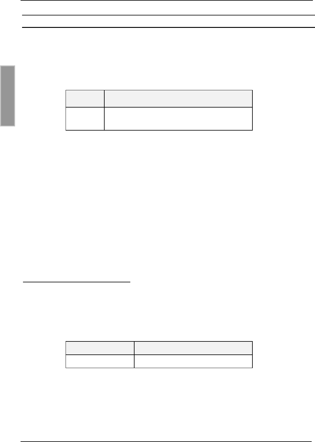
Abbildung 3-1: Leiterplatte mit Jumpern und Anschlußsteckern
Über den Jumper J21 kann die asynchrone Schnittstelle als RS232- oder RS485-Schnittstelle
konfiguriert werden.
Jumper RS232 RS485
J21 1 - 2 2 - 3
Tabelle 3-7: Konfiguration RS232/RS485 Schnittstelle
J74
J73
J21
J72
J23
J24
1
X2 X4
1
2
3
4
5
6
7
8
9
J77
Identifikation System OBIDi-scan
Seite 12 von 34 FEIG ELECTRONIC GmbH
D E U T S C H
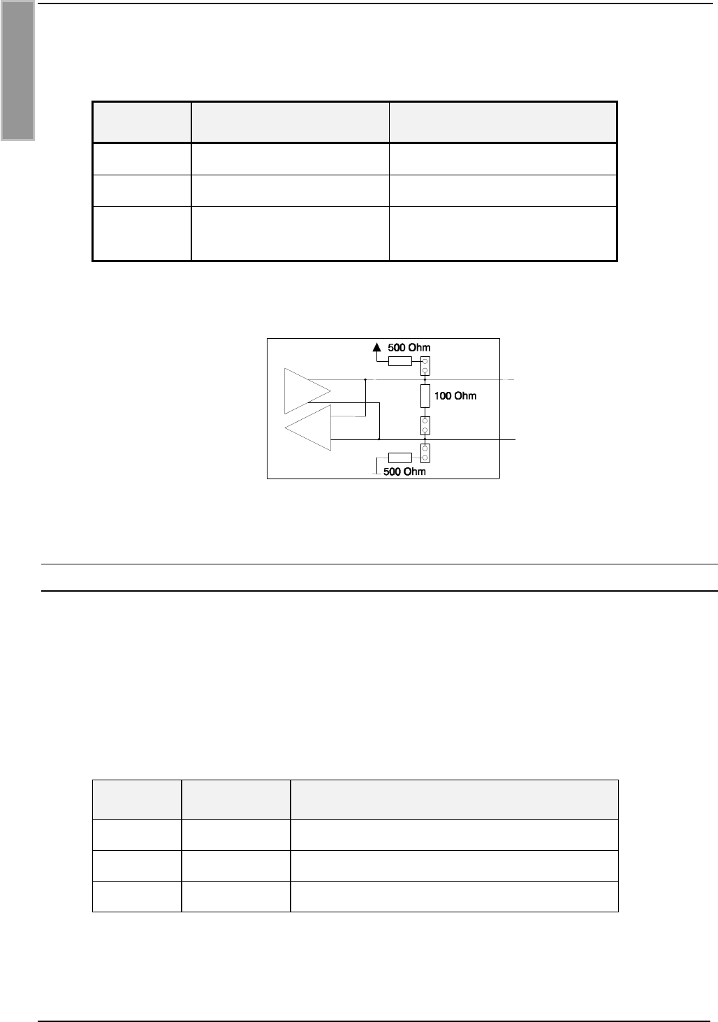
Im Fall der RS485-Schnittstelle können die eventuell benötigten Abschlußwiderstände mit den
Jumpern J73, J74 und J77 zugeschaltet werden.
Jumper geschlossen offen
J73 Pull-Up an RS485 - B ohne Pull-Up an RS485 - B
J74 Pull-Down an RS485 - A ohne Pull-Down an RS485 - A
J77 Abschlußwiderstand
RS485 - A ⇔RS485 - B
ohne Abschlußwiderstand
RS485 - A ⇔RS485 - B
Tabelle 3-8: Konfiguration RS485 Schnittstelle
J73
J77
J74
RS485 - B+
RS485 - A-
Abbildung 3-2: Jumper der RS485 Schnittstelle
3.4.2 RS232-Schnittstelle
Der Anschluß der RS232-Schnittstelle erfolgt über X2.
Die Übertragungsparameter können per Softwareprotokoll konfiguriert werden.
Anschlußbelegung X2 (RS232-Schnittstelle):
Klemme Kurzzeichen Beschreibung
2TxD RS232 – TxD
3RxD RS232 – RxD
5GND RS232 – GND
Tabelle 3-9: Anschlußbelegung der RS232 Schnittstelle
Montageanleitung ID ISC.MR100-A / ID ISC.PR100-A
FEIG ELECTRONIC GmbH Seite 13 von 34
D E U T S C H
3.4.3 RS485 Schnittstelle
Der Anschluß der RS485-Schnittstelle erfolgt über X2.
Die Übertragungsparameter können per Softwareprotokoll konfiguriert werden.
Anschlußbelegung X2 (RS485-Schnittstelle):
Pin Kurzzeichen Beschreibung
2A- RS485 – (A -)
3B+ RS485 – (B +)
5GND RS485 – GND
Tabelle 3-10: Anschlußbelegung der RS485 Schnittstelle
3.4.4 Adresseinstellung für Busbetrieb
Für den Busbetrieb bietet der Reader die Möglichkeit die benötigte Busadresse per Software zu
vergeben.
Die Adressvergabe erfolgt über den Host-Rechner. Mit Hilfe der Software können dem Reader die
Adressen "0" bis "254" zugewiesen werden.
Hinweis:
Da alle Reader werksseitig die Adresse 0 eingestellt haben, müssen sie nacheinander an-
geschlossen und konfiguriert werden.

Identifikation System OBIDi-scan
Seite 14 von 34 FEIG ELECTRONIC GmbH
D E U T S C H
4. Bedien- und Anzeigeelemente
4.1 LED
Die LED des Readers kann per Software konfiguriert werden.
Tabelle 4.1-1 zeigt die Standard-Konfiguration der LED.
Kurzzeichen Beschreibung
LED grün "RUN "
-Signalisiert den ordnungsgemäßen Ablauf der
internen Reader-Software.
-Leuchet, wenn der Reader betriebsbereit ist.
LED rot „LABEL“
-Leuchtet, wenn ein Label erkannt wird.
LED orange „INITIALISIERUNG“
-Blinkt während der Reader-Initialisierung nach dem Einschal-
ten.
Tabelle 4.1-1: Standard-Konfiguration der LED

Montageanleitung ID ISC.MR100-A / ID ISC.PR100-A
FEIG ELECTRONIC GmbH Seite 15 von 34
D E U T S C H
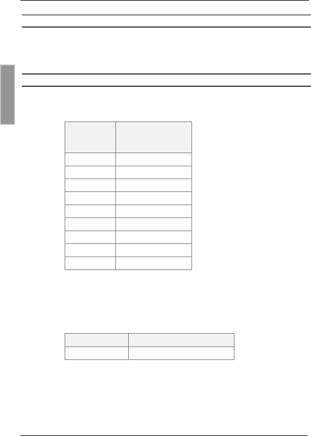
5. Technische Daten
Mechanische Daten
•Gehäuse Kunststoff ABS
geschlossen
•Abmessungen ( B x H x T ) 85 x 145 x 31 mm
•Gewicht 200 g
•Schutzart IP 30
•Farbe RAL 9018
Elektrische Daten
•Spannungsversorgung typisch 12 V DC
max. Spannungsbereich 12 – 24 V DC ±15 %
•Leistungsaufnahme ID ISC.MR100: max. 8 VA
ID ISC.PR100: max. 5 VA
•Betriebsfrequenz 13,56 MHz
•Sendeleistung ID ISC.MR100: 1,0 W
ID ISC.PR100: 0,5 W
•Antennenanschluß
(nur ID ISC.MR100)
SMA Buchse (50Ω)
•Schnittstellen RS232 und RS485 (wahlweise einstellbar)
Funktionelle Eigenschaften
•Unterstützte Transponder I•Code•1, Tag-it-HF, ISO 15693
•Adreßeinstellung für Schnittstelle Software (bis zu 254 Adressen)
•Signalgeber optisch 1 LED ( mehrfarbig – rot / grün)

Identifikation System OBIDi-scan
Seite 16 von 34 FEIG ELECTRONIC GmbH
D E U T S C H
Umgebungsbedingungen
•Temperaturbereich
- Betrieb
- Lagerung
-25°C bis +60°C
-25°C bis +70°C
Angewendete Normen
•Zulassung Funk
- Europa
- USA
EN 300 330
FCC 47 CFR Part 15
•EMV EN 300 683
•Sicherheit
- Europa EN 60950

Montageanleitung ID ISC.MR100-A / ID ISC.PR100-A
FEIG ELECTRONIC GmbH Seite 17 von 34
D E U T S C H
6. Anhang
6.1 Zubehör
Zu dem Reader ist folgendes Zubehör zu erhalten.
Artikel Nr. Bezeichnung Beschreibung
1688.000.00.00 ID NET.12VDC 12 V DC Netzteil mit passendem Stecker
für ID CAB.RS-A.
1690.000.00.00 ID CAB.RS-A Serielles Datenkabel mit integrierter Ver-
sorgungsleitung
1691.000.00.00 ID ISC.MS.MR/PR-A Wandmontagesatz für
ID ISC.MR100 und ID ISC.PR100.
1687.000.00.00 ID CO.RS232/485 Externer RS232/RS485
Umsetzer
1663.000.00.00 ID ISC.ANT340/240 Externe Antenne
Abm.: 340mm x 240mm x 9mm
Schutzart.: IP30
1451.000.00.01 ID ISC.ANT300/300 Externe Antenne
Abm.: 300mm x 300mm x 30mm
Schutzart.: IP65
Identifikation System OBIDi-scan
Seite 18 von 34 FEIG ELECTRONIC GmbH
D E U T S C H
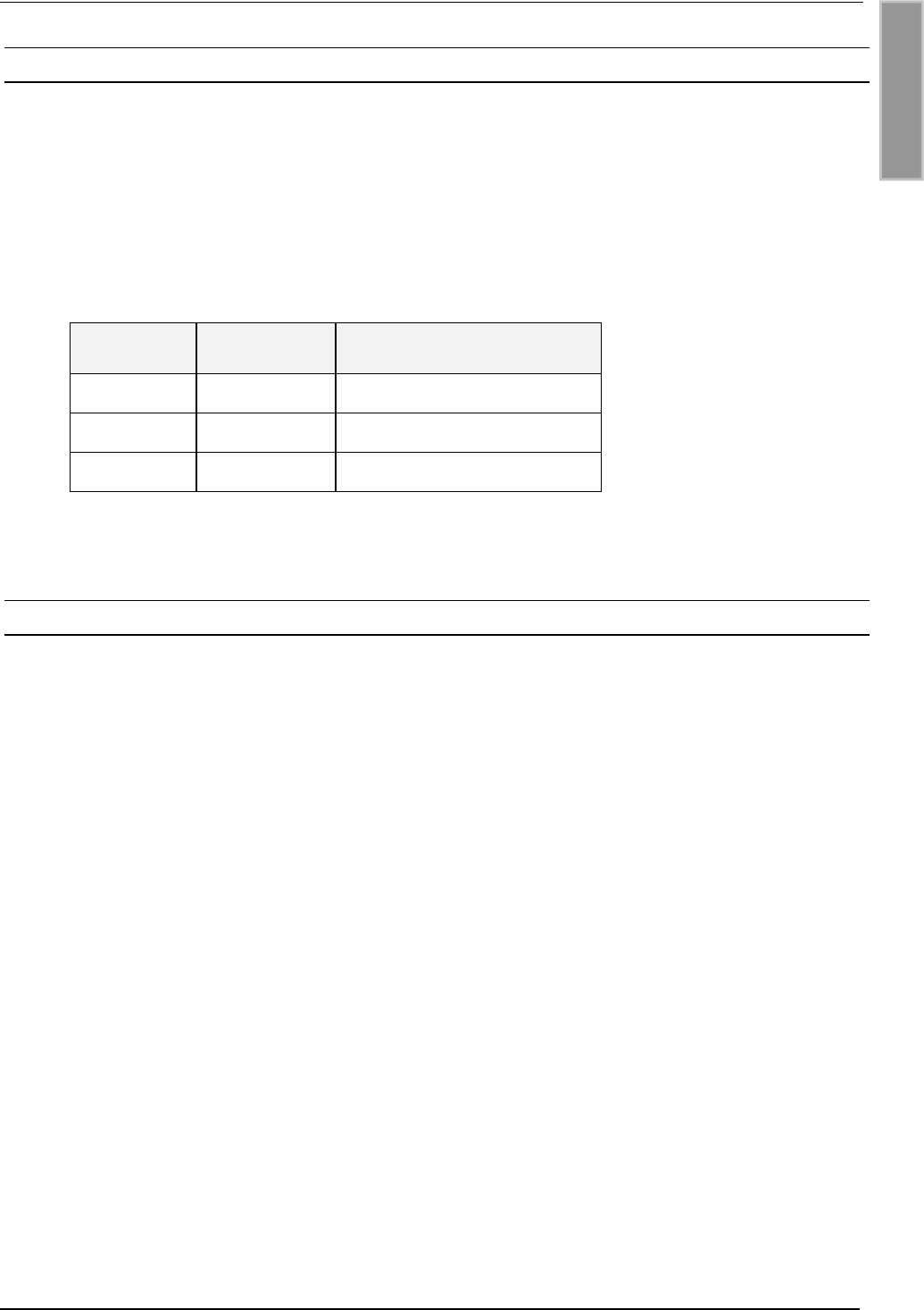
6.1.1 Serielles Datenkabel ID CAB.RS-A
Abbildung 6-1: Serielles Datenkabel mit Spannungsanschluß
Abbildung 6-2: Belegung der DC-Kupplung
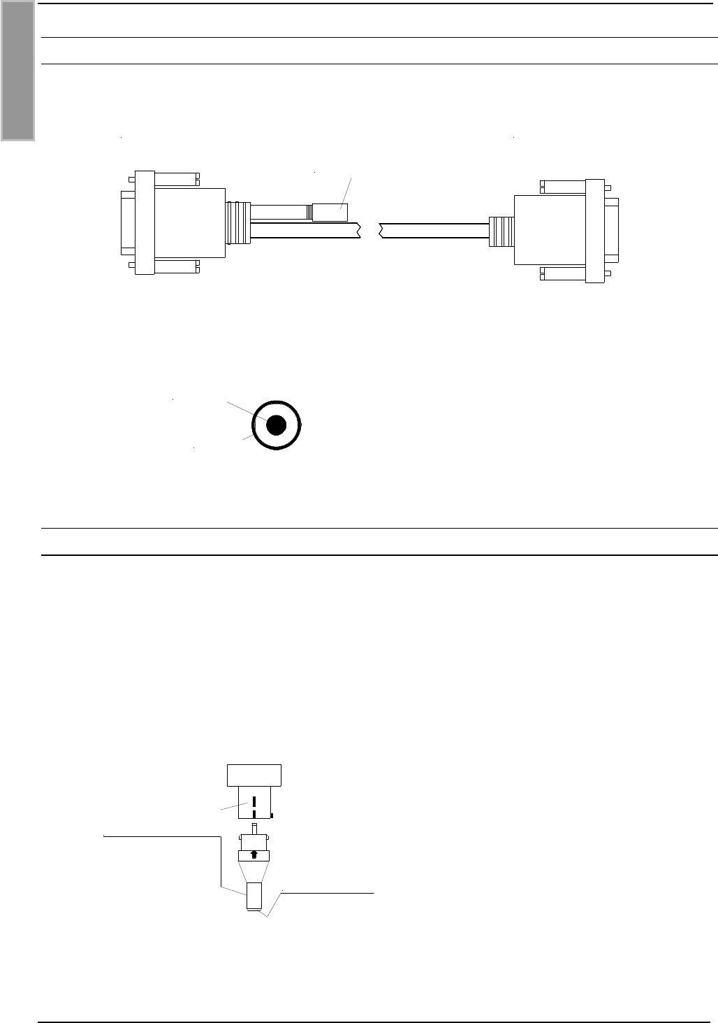
6.1.2 Netzteil ID NET.12VDC
Bei dem Netzteil muß noch der Kupplungsteil mit der korrekten Polarität auf das Netzteil gesteckt
werden.
Achtung: Der Kupplungsteil ist nicht mehr abtrennbar, wenn er einmal eingerastet
ist !
Eine Verpolung kann zur Zerstörung des Gerätes führen.
Abbildung 6-3: Polarität der Kupplung
PC:
9-pol D-Sub Buchse Reader:
9pol. D-Sub Stecker
Versorgung:
DC-Kupplung 2,5mm*5,5mm
+ 12 V DC
AGND
plus - innen
+12 V DC
minus - außen
AGND

Mounting Instruction ID ISC.MR100-A
FEIG ELECTRONIC GmbH Page 19 of 34
E N G L I S H
_________
Edition: cf/01/09/24 -m10202-2de-id-b.doc
© Copyright 2001 by FEIG ELECTRONIC GmbH
Copying of this document, and giving it to others and the use or communication of the contents thereof are
forbidden without express authority. Offenders are liable to the payment of damages. All rights are reserved in
the event of the grant of a patent or the registration of a utility model or design.
Indications made in this manual may be changed without previous notice. With the edition of this manual, all previous
editions become void.
Composition of the information in this manual has been done to the best of our knowledge. FEIG ELECTRONIC GmbH
does not guarantee the correctness and completeness of the details given in this manual and may not be held liable for
damages ensuing from incorrect or incomplete information. Since, despite all our efforts, errors may not be completely
avoided, we are always grateful for your useful tips.
The installation instructions given in this manual are based on advantageous boundary conditions. FEIG ELECTRONIC
GmbH does not give any guarantee promise for perfect function of an OBID®-system in cross surroundings.
FEIG ELECTRONIC GmbH assumes no responsibility for the use of any information contained in this manual and
makes no representation that they free of patent infringement. FEIG ELECTRONIC GmbH does not convey any license
under its patent rights nor the rights of others.
OBID®is a registered trademark of FEIG ELECTRONIC GmbH.

Identifikation System OBIDi-scan
Page 20 of 34 FEIG ELECTRONIC GmbH
E N G L I S H
Type approval
Europe (CE)
When used according to regulation, this radio equipment conforms with the basic requirements of
Article 3 and the other relevant provisions of the R&TTE Guideline 1999/E6 dated March 99.
USA (FCC)
FCC ID: PJMMR100-PR100
This device complies with Part 15 of the FCC Rules. Operation is subject to the following
two conditions:
(1) this device may not cause harmful interference, and
(2) this device must accept any interference received, including interference that may
cause undesired operation.
Unauthorized modifications may void the authority granted under Federal communications
Commission Rules permitting the operation of this device.
ID ISC.MR100:
Approval per FCC 47 CFR CH. I Part 15 applies to use with the
antenna ID ISC.ANT340/240.

Mounting Instruction ID ISC.MR100-A
FEIG ELECTRONIC GmbH Page 21 of 34
E N G L I S H
Contents
1. Safety Instructions / Warning.................................................................................. 22
2Performance Features of the Reader...................................................................... 23
2.1 Performance features ...................................................................................................... 23
2.2 Available Reader-Types................................................................................................... 23
3Assembly and Wiring ............................................................................................... 24
3.1 Power and interface terminal X2..................................................................................... 24
3.2 Supply voltage.................................................................................................................. 25
3.3 Antenna terminal X4 (only ID ISC.MR100)...................................................................... 26
3.4 Asynchronous interface .................................................................................................. 27
3.4.1 Interface configuration using jumpers ......................................................................... 27
3.4.2 RS232 interface .......................................................................................................... 28
3.4.3 RS485 interface .......................................................................................................... 29
3.4.4 Setting the address for bus mode ............................................................................... 29
4Control and Display Elements................................................................................. 30
4.1 LED.................................................................................................................................... 30
5Technical Data .......................................................................................................... 31
6Appendix ................................................................................................................... 33
6.1 Accessories...................................................................................................................... 33
6.1.1 Serial data cable ID CAB.RS-A................................................................................... 34
6.1.2 Power supply ID NET.12VDC ..................................................................................... 34

Identifikation System OBIDi-scan
Page 22 of 34 FEIG ELECTRONIC GmbH
E N G L I S H
1. Safety Instructions / Warning
Please read before startup !
•The device may be used only for the purpose intended by the manufacturer.
•The Mounting Instruction should be kept in an accessible location and handed out to every
user and maintenance person.
•Non-approved modifications and the use of replacement parts and accessories which have not
been purchased or recommended by the manufacturer of the device may cause fires, electrical
shocks and injury. This will furthermore result in exclusion of liability and loss of warranty on
the part of the manufacturer.
•The warranty conditions in effect at the time of purchase shall be considered valid. No liability
is assumed for inappropriate, improper manual or automatic setting of parameters for a device
or for improper use of a device.
•Repairs are to be performed only by the manufacturer.
•Hookup, startup, maintenance, measuring and calibration work on the device must be per-
formed only by electrical specialists who have received the relevant accident prevention train-
ing.
•Before opening the device always turn off the supply voltage and use a test instrument to verify
that the device is unpowered.
•The fact that the indicator lamp is off does not necessarily mean that the device has been dis-
connected from the power supply or that it is without power.
•All work on the device including installation must be in conformance with national electrical
regulations as well as with local code.
•The user has to make sure that the appliance is installed and operated according to the tech-
nical rules of the country of installation as well as other regional regulations. Cable dimensions,
protection, earthing, disconnection, insulation control and excess current protection should be
especially considered.

Mounting Instruction ID ISC.MR100-A
FEIG ELECTRONIC GmbH Page 23 of 34
E N G L I S H
2Performance Features of the Reader
2.1 Performance features
The Reader is designed for reading passive data carriers, so-called „Smart Labels“ at an operating
frequency of 13.56 MHz.
The reader ID ISC.MR100 is suitable for all applications in which moderate reading distances are
required. Also required is an external antenna connected to the Reader.
The ID ISC.PR100 is suitable for all applications which don’t require wide reader ranges.
The reader contains of an internal antenna, so that is no external antenna necessary.
An anti-collision function enables simultaneous reading of up to 30 transponders per second.
The Reader electronics is contained in a plastic housing having an IP30 enclosure rating. The
Reader comes with an asynchronous port which can be configured for RS232 or RS485.
The ability to configure the port means that the Reader can also be operated on a databus with
RS485 interface. The address of the Reader is configured via software.
2.2 Available Reader-Types
Following Reader-Types are available at present:
Reader-Types Description
ID ISC.MR100-A asynchronous interface and external antenna
ID ISC.PR100-A asynchronous interface and internal antenna
Identifikation System OBIDi-scan
Page 24 of 34 FEIG ELECTRONIC GmbH
E N G L I S H
3Assembly and Wiring
The Reader is designed for an office environment. It can be wall-mounted, in this case the wall-
mount kit should be ordered separately. ( see Appendix: 6.1Accessories).
3.1 Power and interface terminal X2
A 9-pin D-sub female socket is located on the circuit board for connecting the supply voltage and
asynchronous interface. See also Fig. 3-1: Circuit board with jumpers and sockets.
X2
Interface
+
Supply voltage
1n.c.
2A-
3B+
4n.c.
5GND
6n.c.
7AGND
8n.c.
9+12 V DC
Table 3-1: Pin configuration X2
A serial data cable with integrated power connection is available for the Reader.
(see 6.1 Accessories and 6.1.1 Serial data cable ID CAB.RS-A).
Feig Article No. Part No.
1690.000.00.00 ID CAB.RS-A
Table 3-2: Serial data cable

Mounting Instruction ID ISC.MR100-A
FEIG ELECTRONIC GmbH Page 25 of 34
E N G L I S H
3.2 Supply voltage
Connect the 12 V DC supply voltage to terminal X2 on the circuit board.
Note:
Reversing the polarity of the supply voltage may destroy the device.
Terminal Name Description
X2 / Pin 9 +12V + 12 V DC – supply voltage
X2 / Pin 7 AGND Ground – supply voltage
Table 3-3: Connecting the supply voltage
Power supply recommendations :
To take full advantage of the Reader module performance, you must use a sufficiently regulated
and noise-free power supply. Preferred is a linear power supply with 12V DC / 580 mA. When us-
ing a switching power supply, be sure that its internal switching frequency is less than 300 kHz.
(see: 6.1 Accessories and 6.1.2 Power supply ID NET.12VDC).
Feig Article No. Part No.
1688.000.00.00 ID NET.12VDC
Table 3-4: Recommended power supply
Identifikation System OBIDi-scan
Page 26 of 34 FEIG ELECTRONIC GmbH
E N G L I S H
3.3 Antenna terminal X4 (only ID ISC.MR100)
An SMA socket is provided on the circuit board for connecting the external antenna.
The maximum tightening torque for the SMA socket is 0.45 Nm.
(Caution: Higher tightening torque will damage the connector.)
Terminal Description
X4 Connecting the external antenna
(input impedance 50Ω)
Table 3-5: Connecting the external antenna
Note:
•The input impedance for the antenna should be calibrated to a value of 50 Ω±(3 Ω∠3°).
•The optimum operating Q factor of the antenna should be in a range of Qoper = 10...20. To
determine the operating Q the antenna must be supplied with a 50 Ohm source such as
a network analyzer or frequency generator.
•To achieve optimum read distances, the length of the antenna lines should not exceed
3.6 m ±0.1 m.
•When connecting an antenna, ensure that it does not exceed the permissible limits pre-
scribed by the national regulations for radio frequency devices.
Installation with FCC Approval:
In countries where FCC approval is required, the ID ISC.MR100 Reader may only be operated
using the antennas listed in Table 3-6. Changes or modifications not expressly authorized by the
relevant approval body may result in revocation of the user’s operating permission.
Article No. Part No.
1663.000.00.00 ID ISC.ANT340/240
Table 3-6: Antennas with FCC Approval
Electrical connection, commissioning, maintenance, measurement and calibration work on
the unit is to be performed only by electrical specialists or persons with equivalent training.
Mounting Instruction ID ISC.MR100-A
FEIG ELECTRONIC GmbH Page 27 of 34
E N G L I S H
3.4 Asynchronous interface
The asynchronous interface can be configured as either RS232 or RS485.
Note:
It is not possible to run both RS232 and RS485 at the same time.
3.4.1 Interface configuration using jumpers
Fig. 3-1: Circuit board with jumpers and sockets
Jumper J21 is used to configure the asynchronous interface as RS232 or RS485.
Jumper RS232RS485
J21 1 - 2 2 - 3
Table 3-7: Configuring as RS232/RS485
J74
J73
J21
J72
J23
J24
1
X2 X4
1
2
3
4
5
6
7
8
9
J77
Identifikation System OBIDi-scan
Page 28 of 34 FEIG ELECTRONIC GmbH
E N G L I S H
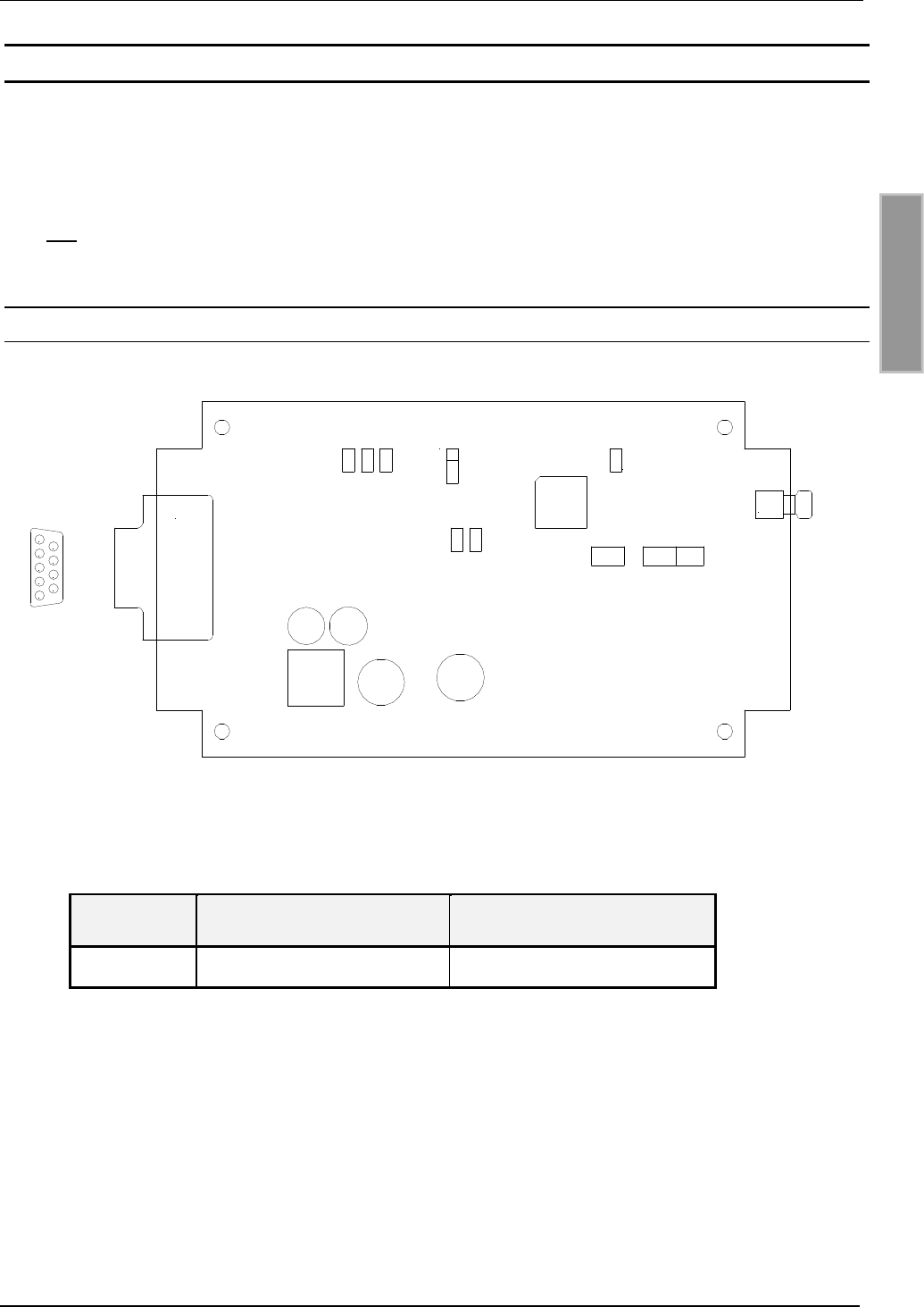
In the case of the RS485 configuration, the termination resistors which may be required can be
inserted using jumpers J73, J74 and J77.
Jumper in out
J73 Pull-Up on RS485 - B out Pull-Up on RS485 - B
J74 Pull-Down on RS485 - A out Pull-Down on RS485 - A
J77 Termination resistor
RS485 - A ⇔RS485 - B
no termination resistor
RS485 - A ⇔RS485 - B
Table 3-8: Configuring the RS485 interface
J73
J77
J74
RS485 - B+
RS485 - A-
Fig. 3-2:Jumper of the RS485 interface
3.4.2 RS232 interface
The RS232 interface is connected through X2.
The transmission parameters can be configured using software protocol.
Pin assignments X2 (RS232 interface):
Terminal Abbrev. Description
2TxD RS232 – TxD
3RxD RS232 – RxD
5GND RS232 – GND
Table 3-9: Wiring assignments for the RS232

Mounting Instruction ID ISC.MR100-A
FEIG ELECTRONIC GmbH Page 29 of 34
E N G L I S H
3.4.3 RS485 interface
The RS485 interface is connected through X2.
The transmission parameters can be configured using software protocol.
Pin assignments X2 (RS485 interface):
Pin Abbrev. Description
2A- RS485 – (A -)
3B+ RS485 – (B +)
5GND RS485 – GND
Table 3-10: Wiring assignments for the RS485 interface
3.4.4 Setting the address for bus mode
For bus operation the Reader can be assigned a bus address using software.
Addresses are assigned by the host computer. Using the software, addresses “0” to “254” can be
assigned to the Reader.
Note:
Since all Readers are factory set with Address 0, you must connect and configure them one
after the other.

Identifikation System OBIDi-scan
Page 30 of 34 FEIG ELECTRONIC GmbH
E N G L I S H
4Control and Display Elements
4.1 LED
The Reader’s LED can be configured through software.
Table 4.1-1 shows the standard configuration of the LED.
Abbreviation Description
LED green "RUN "
-Indicates the Reader software is running properly.
-Turns on when the Reader is ready.
LED red „LABEL“
-Turns on when a label is detected.
LED orange „INITIALIZING“
-Flashes during Reader initialization after power-up.
Table 4.1-1: Standard configuration of the LEDs

Mounting Instruction ID ISC.MR100-A
FEIG ELECTRONIC GmbH Page 31 of 34
E N G L I S H
5Technical Data
Mechanical Data
•Housing ABS plastic
Enclosed
•Dimensions (W x H x D) 85 x 145 x 31 mm
•Weight 200 g
•Enclosure rating IP 30
•Color RAL 9018
Electrical Data
•Supply voltage typical. 12 V DC
max. voltage range 12 – 24 V DC ±15 %
•Power consumption ID ISC.MR100: max. 8 VA
ID ISC.PR100: max. 5 VA
•Operating frequency 13.56 MHz
•Transmitting power ID ISC.MR100: 1,0 W
ID ISC.PR100: 0,5 W
•Antenna connection
(only ID ISC.MR100)
SMA female (50Ω)
•Interfaces RS232 and RS485 (configurable)
Functional properties
•Supported transponders I•Code•1, Tag-it-HF, ISO 15693
•Address setting for interface Software (up to 254 addresses)
•Visual indicators 1 LED ( multicolor – red / green)

Identifikation System OBIDi-scan
Page 32 of 34 FEIG ELECTRONIC GmbH
E N G L I S H
Ambient conditions
•Temperature range
- Operation
- Storage
-25°C to +60°C
-25°C to +70°C
Applicable Norms
•Radio approval
- Europe
- USA
EN 300 330
FCC 47 CFR Part 15
•EMC EN 300 683
•Safety
- Europe EN 60950

Mounting Instruction ID ISC.MR100-A
FEIG ELECTRONIC GmbH Page 33 of 34
E N G L I S H
6Appendix
6.1 Accessories
The following accessories are available for the Reader.
Article No. Part No. Description
1688.000.00.00 ID NET.12VDC 12 V DC power supply with suitable con-
nector for ID CAB.RS-A
1690.000.00.00 ID CAB.RS-A Serial data cable with integrated supply
voltage line
1691.000.00.00 ID ISC.MS.MR/PR-A Wall mounting kit for
ID ISC.MR100. and ID ISC.PR100.
1687.000.00.00 ID CO.RS232/485 External RS232/RS485
converter
1663.000.00.00 ID ISC.ANT340/240 External antenna
Dimensions: 340mm x 240mm x 9mm
Enclosure rating.: IP30
1451.000.00.01 ID ISC.ANT300/300 External antenna
Dimensions: 300mm x 300mm x 30mm
Enclosure rating.: IP65
Identifikation System OBIDi-scan
Page 34 of 34 FEIG ELECTRONIC GmbH
E N G L I S H
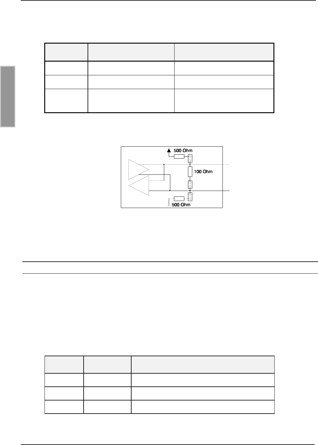
6.1.1 Serial data cable ID CAB.RS-A
Fig. 6-1: Serial data cable with supply voltage connection
Fig. 6-2: DC adapter configuration
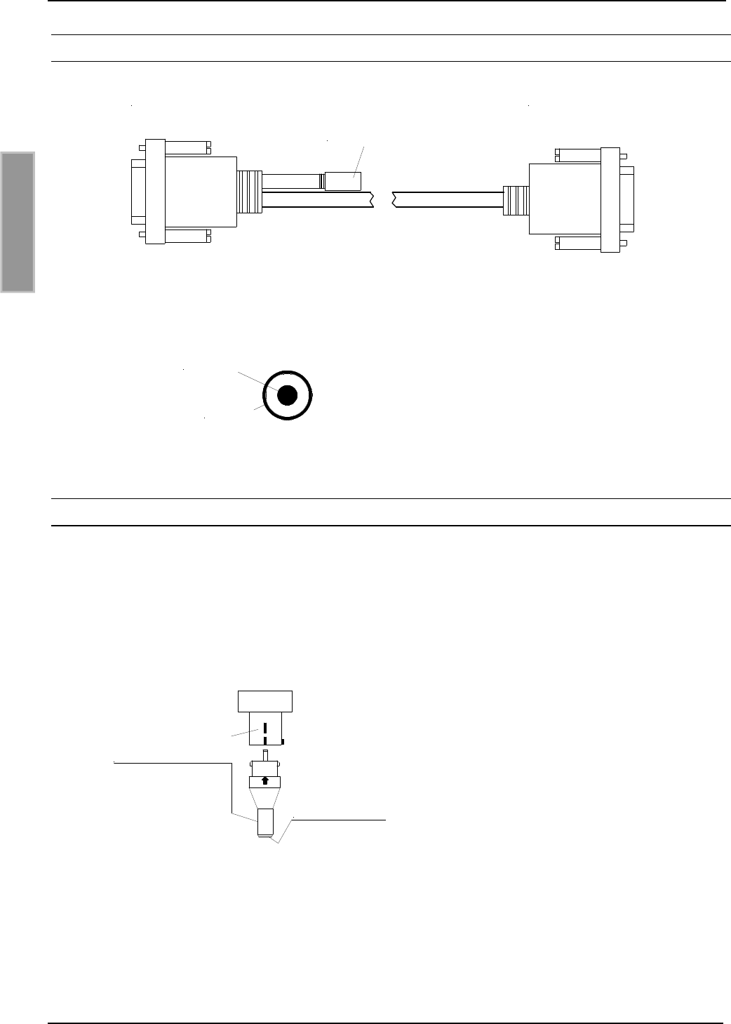
6.1.2 Power supply ID NET.12VDC
The AC adapter must be plugged into the power supply while observing the correct polarity.
Caution: The AC adapter can no longer be unplugged once it has been inserted !
Reversing the polarity may destroy the device.
Fig. 6-3: Polarity of the adapter
PC:
9-pin D-sub female Reader:
9-pin D-sub male
Supply:
DC adapter 2.5mm*5.5mm
+ 12 V DC
AGND
plus - inside
+12 V DC
minus - outside
AGND