Feig Electronic MR100-PR100 Passive Tag Reader User Manual Operation Manual
Feig Electronic GmbH Passive Tag Reader Operation Manual
UserManual.wiki
>
Feig Electronic
>
MR100-PR100 User Manual
>
Users Manual
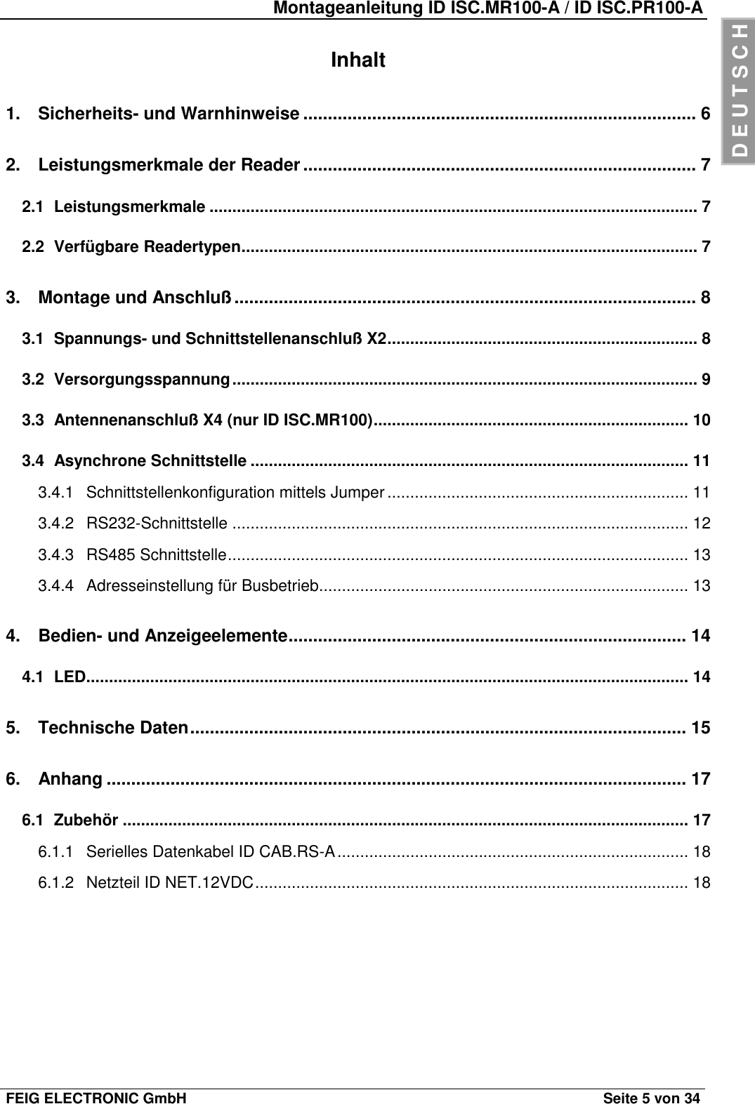
Contents
1.
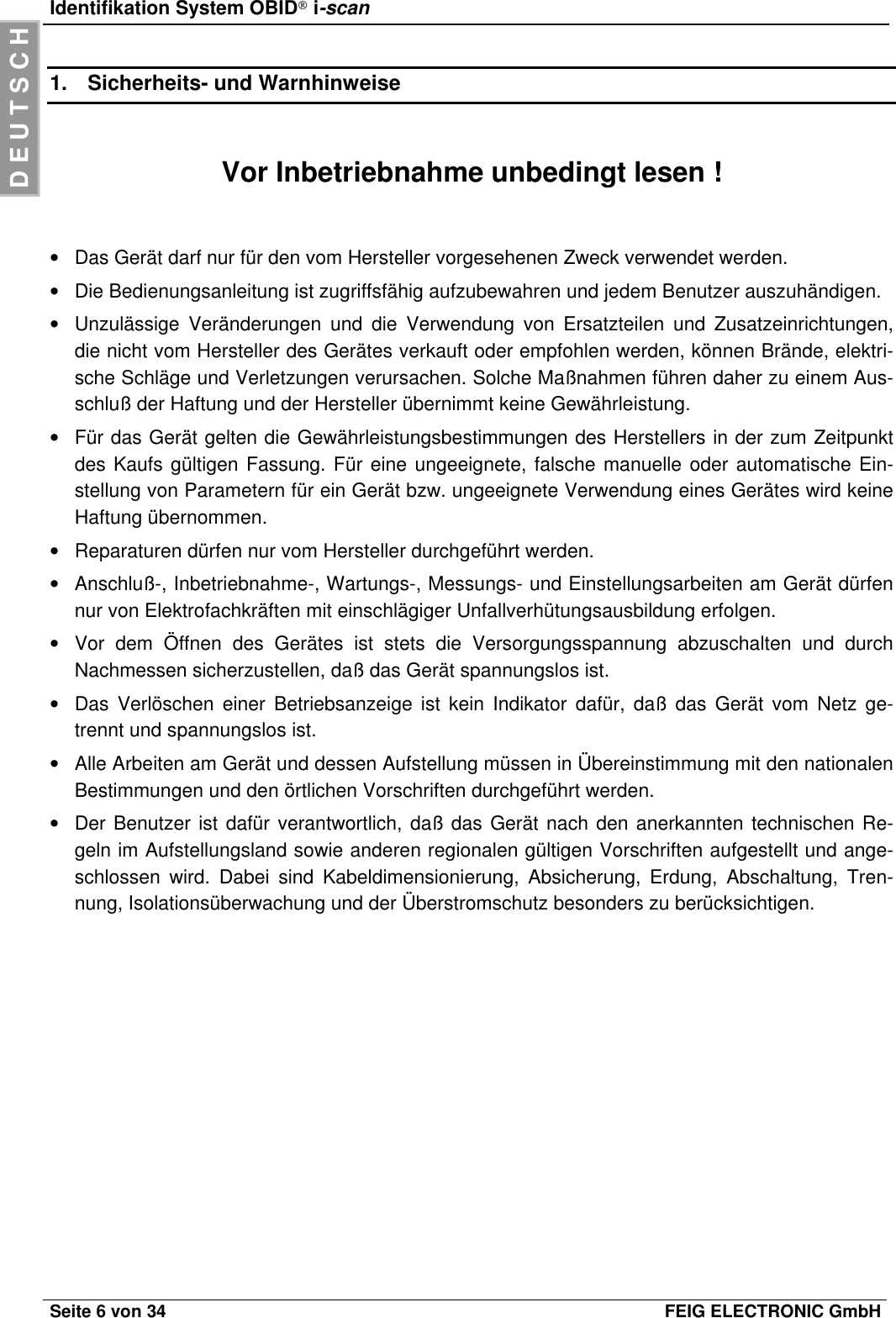
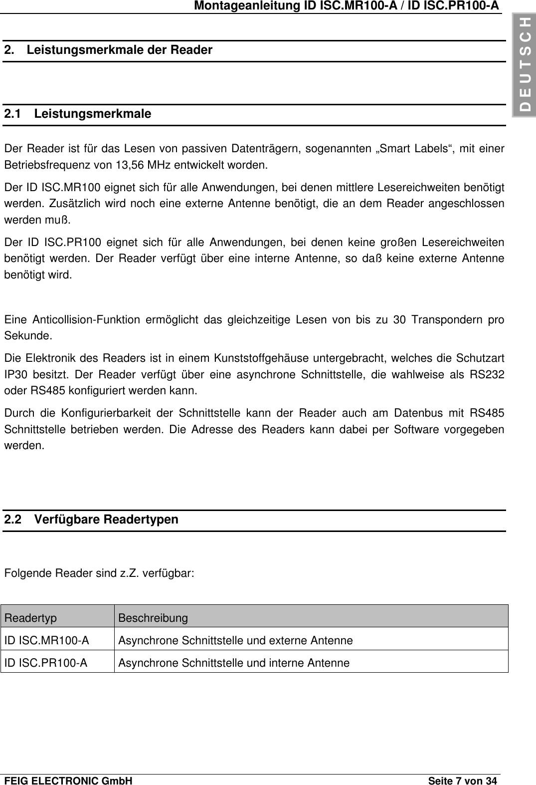
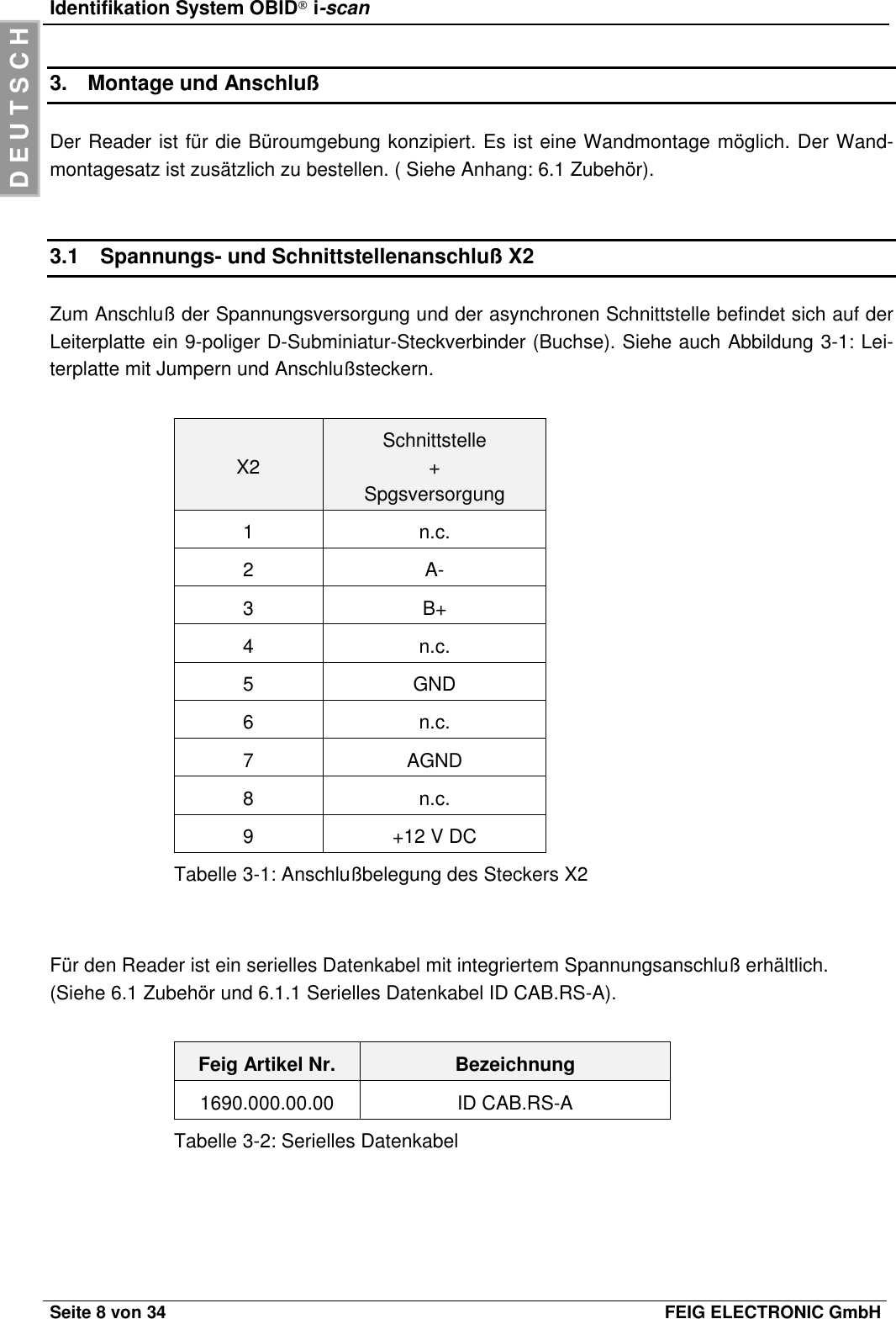
Users Manual
2.
Installation Guide
Users Manual
Navigation menu
Upload a User Manual
Namespaces
Wiki Guide
HTML
PDF
Info
Views
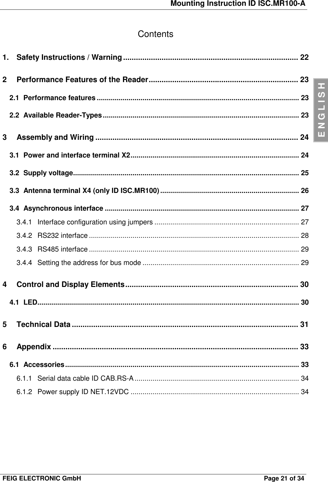
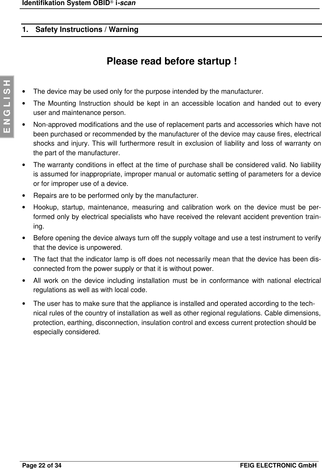
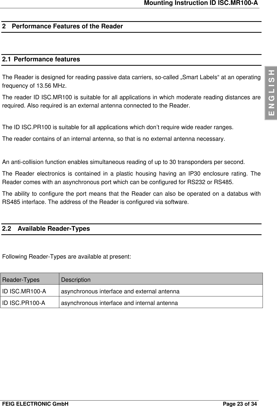
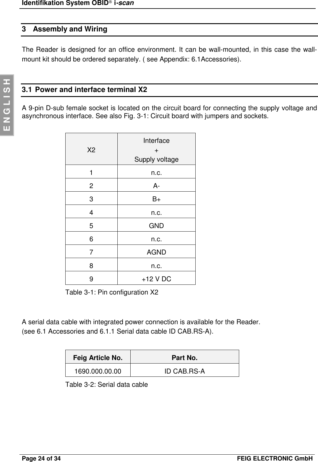
User Manual
Discussion / Help
Navigation