Feig Electronic MRU102 RFID Reader User Manual Annex No
Feig Electronic GmbH RFID Reader Annex No
UserManual.wiki
>
Feig Electronic
>
MRU102 User Manual
user manual
Navigation menu
Upload a User Manual
Namespaces
Wiki Guide
HTML
PDF
Info
Views
User Manual
Discussion / Help
Navigation
![OBID i-scan ® UHF Integration ID ISC.MRMU102-A FEIG ELECTRONIC GmbH Page 3 of 21 Integration Manual M21112-1e-ID-B.docx General information's regarding this document • The sign "" indicates extensions or changes of this manual compared with the former issue. • If bits within one byte are filled with "-", these bit spaces are reserved for future extensions or for internal testing- and manufacturing-functions. These bit spaces must not be changed, as this may cause faulty operation of the reader. • The following figure formats are used: 0...9: for decimal figures 0x00...0xFF: for hexadecimal figures, b0...1 for binary figures. • The hexadecimal value in brackets "[ ]" marks a control byte (command).](https://usermanual.wiki/Feig-Electronic/MRU102/User-Guide-1857283-Page-4.png)
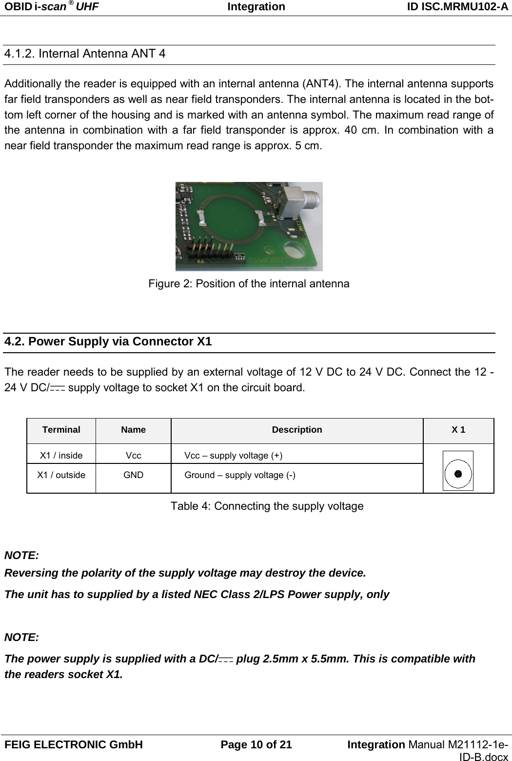
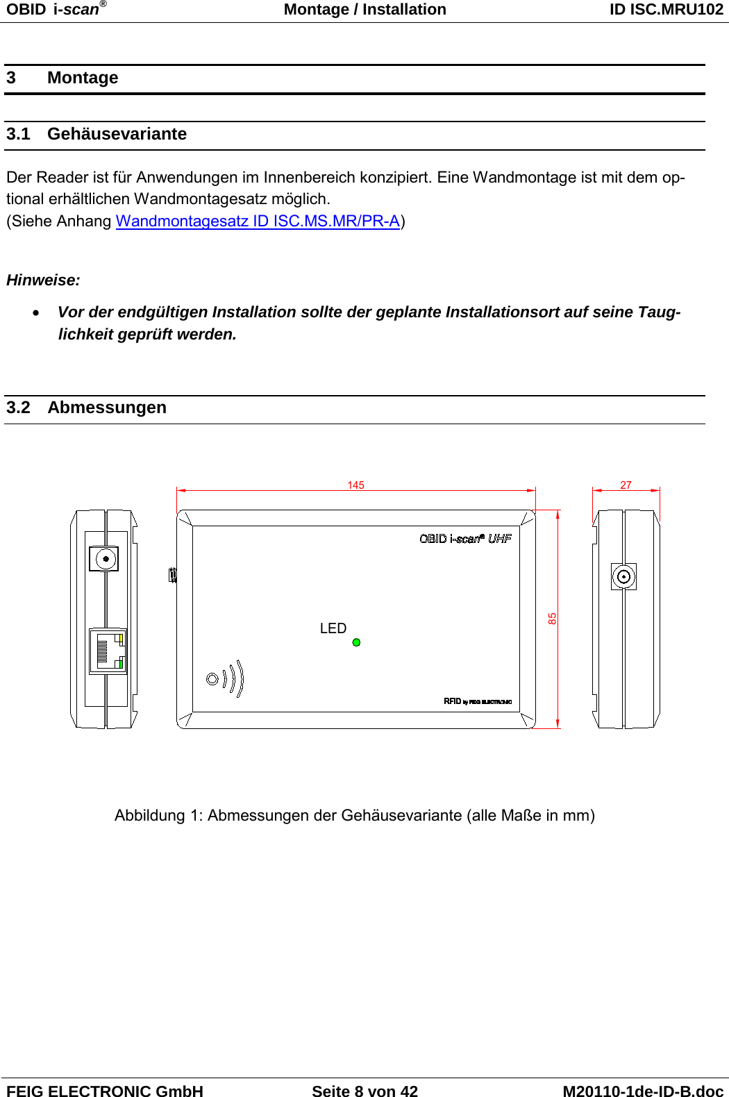
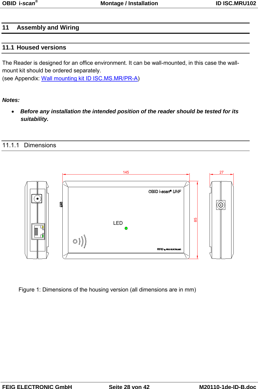
![OBID i-scan ® UHF Integration ID ISC.MRMU102-A FEIG ELECTRONIC GmbH Page 7 of 21 Integration Manual M21112-1e-ID-B.docx 3. Assembly and Wiring 3.1. Module Versions This reader version has been designed for mounting in other equipment. NOTE: Before any installation the intended position of the reader should be tested for its suitabil-ity. 3.1.1. Dimensions 77137Ø3,3Ø7125107,565LEDANT1FE 74168,554,529,5X2X338,5ANT222,5ANT34,75[DB1] Figure 1: Dimensions of the housing version (all dimensions are in mm)](https://usermanual.wiki/Feig-Electronic/MRU102/User-Guide-1857283-Page-8.png)