Feig Electronic MRU102 RFID Reader User Manual Annex No
Feig Electronic GmbH RFID Reader Annex No
user manual

Date: 2012-06-11
Vers. no. 1.12
m. dudde hochfrequenz-technik
Rottland 5a
D-51429 Bergisch Gladbach/ Germany
Tel: +49 2207-96890
Fax +49 2207-968920
Annex no. 5
User Manual
INTEGRATION
final – public (B)
2012-12-03 – Integration Manual M21112-1e-ID-B.docx
ID ISC.MRMU102-A
Module Version

OBID
i-scan
®
UHF
Integration
ID ISC.MRMU102-A
FEIG ELECTRONIC GmbH Page 2 of 21 Integration Manual M21112-1e-
ID-B.docx
Note
Copyright 2012 by
FEIG ELECTRONIC GmbH
Lange Strasse 4
D-35781 Weilburg
Tel.: +49 6471 3109-0
http://www.feig.de
With the edition of this document, all previous editions become void. Indications made in this manual may be
changed without previous notice.
Copying of this document, and giving it to others and the use or communication of the contents thereof are
forbidden without express authority. Offenders are liable to the payment of damages. All rights are reserved
in the event of the grant of a patent or the registration of a utility model or design.
Composition of the information in this document has been done to the best of our knowledge. FEIG
ELECTRONIC GmbH does not guarantee the correctness and completeness of the details given in this
manual and may not be held liable for damages ensuing from incorrect or incomplete information. Since,
despite all our efforts, errors may not be completely avoided, we are always grateful for your useful tips.
The instructions given in this manual are based on advantageous boundary conditions. FEIG ELECTRONIC
GmbH does not give any guarantee promise for perfect function in cross environments and does not give
any guaranty for the functionality of the complete system which incorporates the subject of this document.
FEIG ELECTRONIC call explicit attention that devices which are subject of this document are not designed
with components and testing methods for a level of reliability suitable for use in or in connection with surgical
implants or as critical components in any life support systems whose failure to perform can reasonably be
expected to cause significant injury to a human. To avoid damage, injury, or death, the user or application
designer must take reasonably prudent steps to protect against system failures.
Use Exclusion in Transportation Market: Devices which are subject of this document may NOT be sold,
used, leased, offer for sale, or otherwise transferred, exported, and imported by anyone in the Transportation
Market. “Transportation Market” means (i) Electronic Toll and Traffic Management (ETTM), (ii) Public Sector
Vehicle Registration, Inspection and Licensing Programs, (iii) Railroad Locomotive and Wagon tracking, (iv)
airport based ground transportation management systems (GTMS) and taxi dispatch, (v) revenue based
parking, and (vi) vehicle initiated mobile payment applications, where the RFID sticker/tag is initially attached
to the vehicle but not incorporated at the point of vehicle manufacture.
FEIG ELECTRONIC GmbH assumes no responsibility for the use of any information contained in this docu-
ment and makes no representation that they free of patent infringement. FEIG ELECTRONIC GmbH does
not convey any license under its patent rights nor the rights of others.
OBID® and OBID i-scan® are registered trademarks of FEIG ELECTRONIC GmbH.

OBID
i-scan
®
UHF
Integration
ID ISC.MRMU102-A
FEIG ELECTRONIC GmbH Page 3 of 21 Integration Manual M21112-1e-
ID-B.docx
General information's regarding this document
• The sign "" indicates extensions or changes of this manual compared with the former issue.
• If bits within one byte are filled with "-", these bit spaces are reserved for future extensions or
for internal testing- and manufacturing-functions. These bit spaces must not be changed, as this
may cause faulty operation of the reader.
• The following figure formats are used:
0...9: for decimal figures
0x00...0xFF: for hexadecimal figures,
b0...1 for binary figures.
• The hexadecimal value in brackets "[ ]" marks a control byte (command).

OBID
i-scan
®
UHF
Integration
ID ISC.MRMU102-A
FEIG ELECTRONIC GmbH Page 4 of 21 Integration Manual M21112-1e-
ID-B.docx
Contents
1. Safety Instructions / Warning - Read before start-up ! 5
2. Performance Features of the Reader 6
2.1. Available Reader Types .................................................................................................... 6
2.2. Optional Accessories ........................................................................................................ 6
3. Assembly and Wiring 7
3.1. Module Versions ................................................................................................................ 7
3.1.1. Dimensions .................................................................................................................. 7
4. Connections 8
4.1. Antenna Terminals ............................................................................................................ 8
4.1.1. External Antenna ANT 1 - 3 ......................................................................................... 8
4.1.2. Internal Antenna ANT 4 .............................................................................................. 10
4.2. Power Supply via Connector X1 ..................................................................................... 10
4.3. RS232 Interface on Connector X2 .................................................................................. 11
4.4. USB Interface on Connector X3 ...................................................................................... 12
5. Control and Display Elements 12
5.1. LED ................................................................................................................................... 12
6. Technical Data 13
7. Radio Approvals 16
7.1. Europe (CE) ...................................................................................................................... 16
7.2. Declaration of Conformity ............................................................................................... 17
7.3. USA (FCC) and Canada (IC) ............................................................................................ 19
7.3.1. USA (FCC) and Canada (IC) warning notices ............................................................ 19
7.3.2. USA (FCC) and Canada (IC) approved antennas ...................................................... 20
ANNEX A - Accessories ......................................................................................................... 21

OBID
i-scan
®
UHF
Integration
ID ISC.MRMU102-A
FEIG ELECTRONIC GmbH Page 5 of 21 Integration Manual M21112-1e-
ID-B.docx
1. Safety Instructions / Warning - Read before start-up !
• The device may only be used for the intended purpose designed by for the manufacturer.
• The operation manual should be conveniently kept available at all times for each user.
• Unauthorized changes and the use of spare parts and additional devices which have not been
sold or recommended by the manufacturer may cause fire, electric shocks or injuries. Such
unauthorized measures shall exclude any liability by the manufacturer.
• The liability-prescriptions of the manufacturer in the issue valid at the time of purchase are valid
for the device. The manufacturer shall not be held legally responsible for inaccuracies, errors,
or omissions in the manual or automatically set parameters for a device or for an incorrect
application of a device.
• Repairs may only be executed by the manufacturer.
• Installation, operation, and maintenance procedures should only be carried out by qualified
personnel.
• Use of the device and its installation must be in accordance with national legal requirements
and local electrical codes .
• When working on devices the valid safety regulations must be observed.
• Special advice for carriers of cardiac pacemakers:
Although this device doesn't exceed the valid limits for electromagnetic fields you should keep
a minimum distance of 25 cm between the device and your cardiac pacemaker and not stay in
an immediate proximity of the device respective the antenna for some time.

OBID
i-scan
®
UHF
Integration
ID ISC.MRMU102-A
FEIG ELECTRONIC GmbH Page 6 of 21 Integration Manual M21112-1e-
ID-B.docx
2. Performance Features of the Reader
The Reader ID ISC.MRMU102 is designed for reading of passive data carriers, so-called „Smart
Labels“ at an operating frequency in the UHF band between 860 MHz and 960 MHz. Transponders
according to EPC Class1 Gen2 are supported. Optional an Upgrade Code for the reading of ISO
18000-6-C transponders is available. The reader is designed for application with small tag popula-
tion.
The reader module is equipped with 3 SMA connectors for conduction of external antennas (ANT1
– ANT3). Additional an integrated antenna (ANT4) is available.
For Host communication the reader provides an asynchronous RS232 interface and an USB inter-
face.
The reader is designed for use in applications with small tag populations. Maximum 10 tags at the
same time into the antenna field can be processed.
2.1. Available Reader Types
The following reader types are currently available:
Table 1: Available Reader Types
Reader type Description
ID ISC.MRMU102-A
Module version with asynchronous RS232- and USB-Interface;
3 SMA connectors for external antennas;
1 integrated antenna;
2.2. Optional Accessories
Optional Accessories are listed in the appendix.
OBID
i-scan
®
UHF
Integration
ID ISC.MRMU102-A
FEIG ELECTRONIC GmbH Page 7 of 21 Integration Manual M21112-1e-
ID-B.docx
3. Assembly and Wiring
3.1. Module Versions
This reader version has been designed for mounting in other equipment.
NOTE:
Before any installation the intended position of the reader should be tested for its suitabil-
ity.
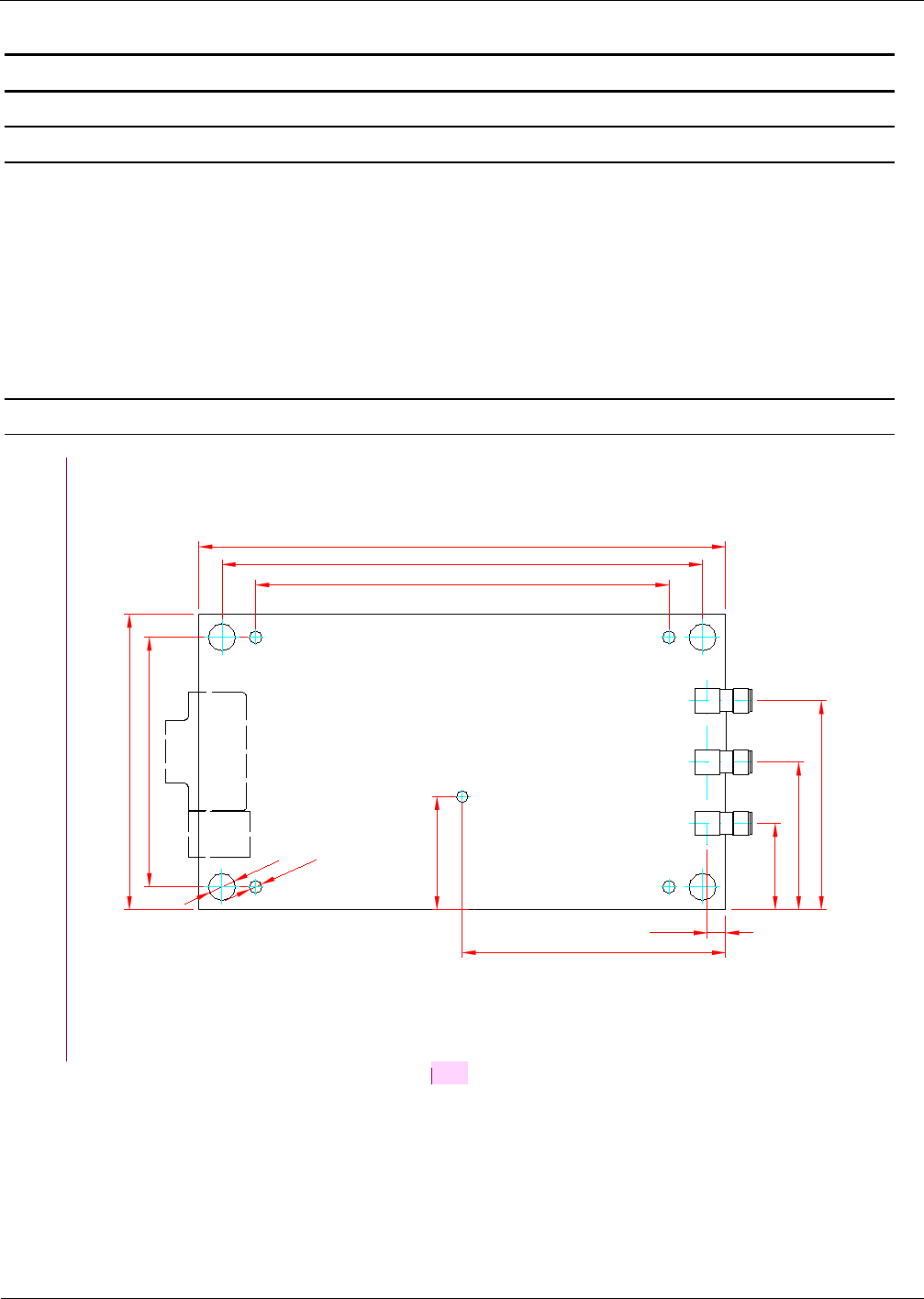
3.1.1. Dimensions
77
137
Ø3,3
Ø7
125
107,5
65
LED
ANT1
FE 741
68,5
54,5
29,5
X2
X3
38,5
ANT2
22,5
ANT3
4,75
[DB1]
Figure 1: Dimensions of the housing version (all dimensions are in mm)

OBID
i-scan
®
UHF
Integration
ID ISC.MRMU102-A
FEIG ELECTRONIC GmbH Page 8 of 21 Integration Manual M21112-1e-
ID-B.docx
4. Connections
The module version of the reader is equipped with an asynchronous RS232 Interface (X2) and a
USB Interface (X3). The Table 2: Connectors shows which connector can be used for the different
interface cable.
Table 2: Connectors
Connector Description
ANT 1-3 External Antenna ANT 1 - 3
ANT 4 Internal Antenna ANT 4
X1 Power Supply via Connector X1
X2 RS232 Interface on Connector X2
X3 USB Interface on Connector X3
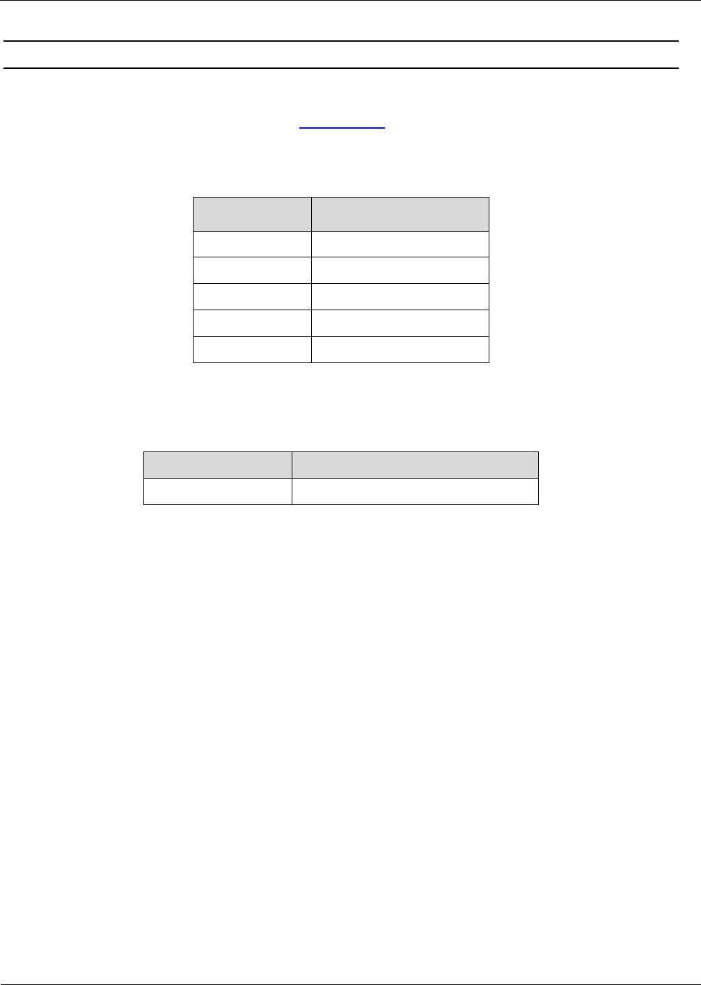
4.1. Antenna Terminals
4.1.1. External Antenna ANT 1 - 3
Three SMA sockets are provided on the circuit board for connecting of the external antennas.
The maximum tightening torque for the SMA socket is 0.45 Nm.
CAUTION:
Higher tightening torque will damage the connector.
Table 3: Connecting an external antenna
Terminal Description
ANT 1-3 Connecting the external antenna
(input impedance 50Ω)
NOTE:
When connecting an antenna, ensure that it does not exceed the permissible limits pre-
scribed by the national regulations for radio frequency devices.

OBID
i-scan
®
UHF
Integration
ID ISC.MRMU102-A
FEIG ELECTRONIC GmbH Page 9 of 21 Integration Manual M21112-1e-
ID-B.docx
OBID
i-scan
®
UHF
Integration
ID ISC.MRMU102-A
FEIG ELECTRONIC GmbH Page 10 of 21 Integration Manual M21112-1e-
ID-B.docx
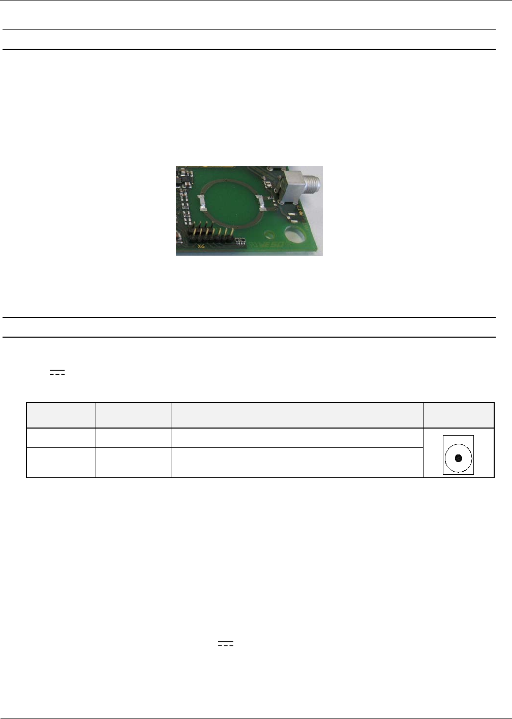
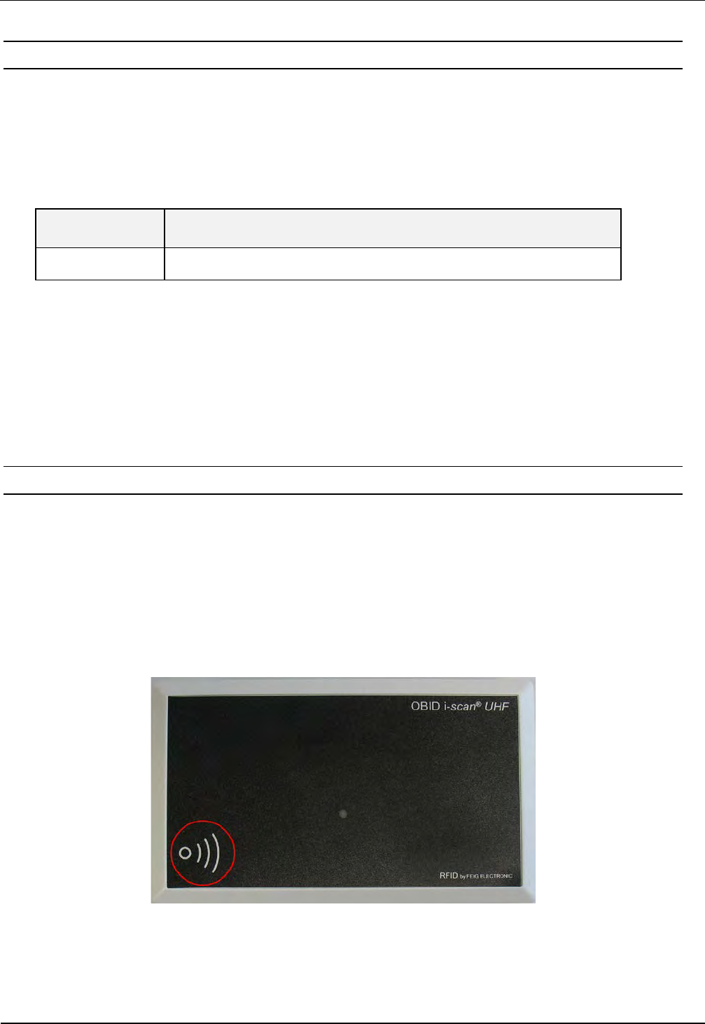
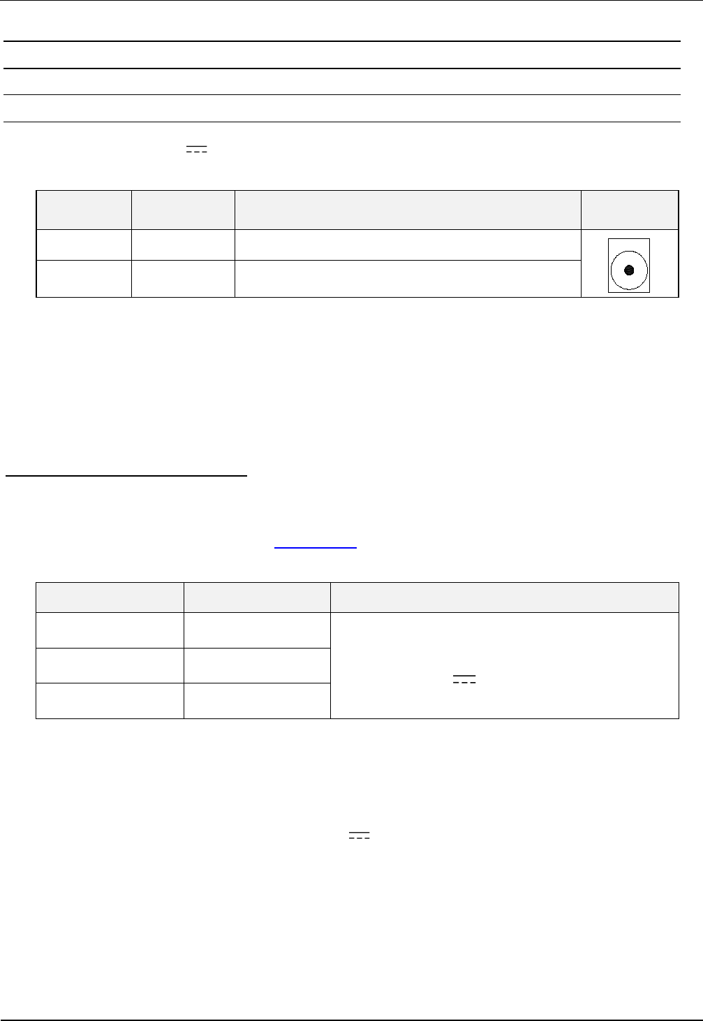
4.1.2. Internal Antenna ANT 4
Additionally the reader is equipped with an internal antenna (ANT4). The internal antenna supports
far field transponders as well as near field transponders. The internal antenna is located in the bot-
tom left corner of the housing and is marked with an antenna symbol. The maximum read range of
the antenna in combination with a far field transponder is approx. 40 cm. In combination with a
near field transponder the maximum read range is approx. 5 cm.
Figure 2: Position of the internal antenna
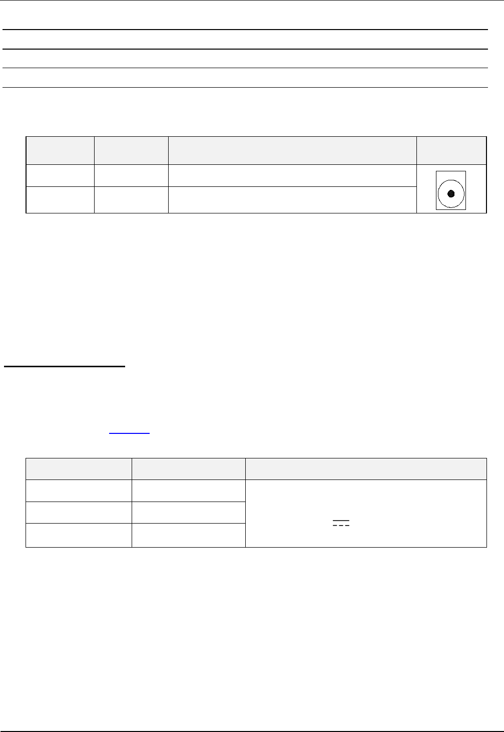
4.2. Power Supply via Connector X1
The reader needs to be supplied by an external voltage of 12 V DC to 24 V DC. Connect the 12 -
24 V DC/ supply voltage to socket X1 on the circuit board.
Terminal Name Description X 1
X1 / inside Vcc Vcc – supply voltage (+)
X1 / outside GND Ground – supply voltage (-)
Table 4: Connecting the supply voltage
NOTE:
Reversing the polarity of the supply voltage may destroy the device.
The unit has to supplied by a listed NEC Class 2/LPS Power supply, only
NOTE:
The power supply is supplied with a DC/ plug 2.5mm x 5.5mm. This is compatible with
the readers socket X1.
OBID
i-scan
®
UHF
Integration
ID ISC.MRMU102-A
FEIG ELECTRONIC GmbH Page 11 of 21 Integration Manual M21112-1e-
ID-B.docx
4.3. RS232 Interface on Connector X2
For the connection of the asynchronous interface RS232 the reader provides a 9-pin D-
Subminiature female connector. (See also Connections).
Table 5: Connection assignment of the connector X2
X2 Interface
2 TxD
3 RxD
5 GND
7 GND
1;4;6;8;9 n.c.
For this reader a serial cable is available.
Table 6: Serial Data Cable
Feig Part No. Description
1690.000.00 ID CAB.RS-A
Interface parameter can be configured via software protocol (e.g. ISOStart). Further information
can be found in the System Manual H10410-Xe-ID-B.pdf of the reader.

OBID
i-scan
®
UHF
Integration
ID ISC.MRMU102-A
FEIG ELECTRONIC GmbH Page 12 of 21 Integration Manual M21112-1e-
ID-B.docx
4.2. USB Interface on Connector X3
There is a USB-socket X3 on board for the connection of the USB-Interface. The pinout is stand-
ardized. The data rate is reduced to 12 Mbit (USB full speed). A standard USB-cable can be used.
Figure 3: USB interface for host communication
NOTE:
The length of the USB-cable can be a max. of 5 meter. It isn’t allowed to use longer cables!
The reader must be powered with a external power supply even if it is connected to a “high
powered port”.
5. Control and Display Elements
5.1. LED
The Reader’s LED can be configured through software.
The following Table 8: Default Configuration of the LEDs shows the default setting.
Table 7: Default Configuration of the LEDs
Abbreviation Description
LED green "RUN "
- Turns on when the Reader is ready
LED red
„LABEL“
- Turns on when a transponder is detected.
- Flashes if RF-Warning (red – green alternating with 8Hz)
(Temperature alarm, short circuit on antenna output)
LED orange „INITIALIZING“
- Flashes during Reader initialization after power-up.

OBID
i-scan
®
UHF
Integration
ID ISC.MRMU102-A
FEIG ELECTRONIC GmbH Page 13 of 21 Integration Manual M21112-1e-
ID-B.docx
6. Technical Data
MECHANICAL DATA
Housing -
Dimension (W x H x D) 137 mm x 77 mm x 17 mm
Weight 60 g
Protection Class -
Colour -
ELECTRICAL DATA
Power Supply 12 V DC – 24 V DC
Power Consumption max. 7 W
Operating Frequency 860 MHz to 960 MHz
RF-Power max. 500 mW ± 1,5 dB
Antenna Connector 3 x SMA female(50 Ω)
1 x integrated Antenna (ANT4)
Interfaces USB (Full Speed)
RS232
FUNCTIONAL PROPERTIES
Protocol Modes FEIG ISO HOST (Advanced Protocol Frame)
Buffered Read Mode
Scan Mode (RS232, USB: HID Mode)
Supported Transponder Types EPC Class 1 Generation 2
ISO 18000-6-C (Upgrade Code required)
Signaller 1 LED (multi-colour red and green)

OBID
i-scan
®
UHF
Integration
ID ISC.MRMU102-A
FEIG ELECTRONIC GmbH Page 14 of 21 Integration Manual M21112-1e-
ID-B.docx
Further Features Anticollision (max. 10 Transponders)
RSSI
Temperature Monitoring*
AMBIENT CONDITIONS
Temperature Range
• Operation
• Storage
-25 °C to +55 °C
-25 °C to +85 °C
Humidity 5 % to 95 % non-condensing
APPLICABLE STANDARDS
Radio Regulation
• Europe
• USA
• Canada
EN 302 208
FCC 47 CFR Part 15
IC RSS-Gen, RSS-210
EMC EN 301 489
Vibration EN 60068-2-6
10 Hz bis 150 Hz: 0,075 mm / 1 g
Shock EN 60068-2-27
Accelleration 30 g

OBID
i-scan
®
UHF
Integration
ID ISC.MRMU102-A
FEIG ELECTRONIC GmbH Page 15 of 21 Integration Manual M21112-1e-
ID-B.docx
* Caution: Overheating of the device may result in performance losses. It is recommended to activate the RF of the reader only if there is a transponder in
the detection range of an antenna.

OBID
i-scan
®
UHF
Integration
ID ISC.MRMU102-A
FEIG ELECTRONIC GmbH Page 16 of 21 Integration Manual M21112-1e-
ID-B.docx
7. Radio Approvals
7.1. Europe (CE)
When used according to regulation, this radio equipment conforms with the basic requirements of
Article 3 and the other relevant provisions of the R&TTE Guideline 1999/E6 dated March 99.
Equipment Classification according to ETSI EN 301 489: Class 2

OBID
i-scan
®
UHF
Integration
ID ISC.MRMU102-A
FEIG ELECTRONIC GmbH Page 17 of 21 Integration Manual M21112-1e-
ID-B.docx
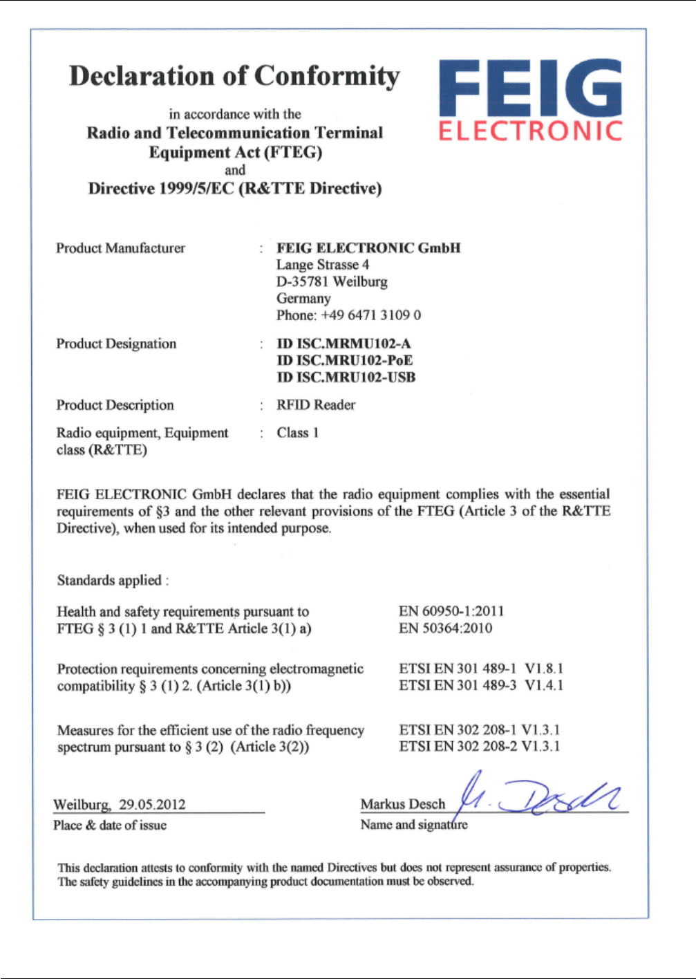
7.2. Declaration of Conformity
OBID
i-scan
®
UHF
Integration
ID ISC.MRMU102-A
FEIG ELECTRONIC GmbH Page 18 of 21 Integration Manual M21112-1e-
ID-B.docx

OBID i-scan ® UHF
Integration
ID ISC.MRMU102-A
FEIG ELECTRONIC GmbH
Page 19 of 21
Integration Manual M21112-1e-
ID-B.docx
7.3. USA (FCC) and Canada (IC)
7.3.1. USA (FCC) and Canada (IC) warning notices
Product name:
ID ISC.MRMU102-A
Reader name:
ID ISC.MRMU102-A
FCC ID:
IC:
PJMMRU102
6633A-MRM102
Notice for USA and
Canada
This device complies with Part 15 of the FCC Rules and with
RSS-210 of Industry Canada.
Operation is subject to the following two conditions.
(1) this device may not cause harmful interference, and (2)
this device must accept any interference received,
including interference that may cause undesired operation.
Unauthorized modifications may void the authority granted under
Federal communications Commission Rules permitting the operation
of this device.
This equipment has been tested and found to comply with the limits for
a Class A digital device, pursuant to Part 15 of the FCC Rules. These
limits are designed to provide reasonable protection against harmful
interference when the equipment is operated in a commercial
environment. This equipment generates, uses, and can radiate radio
frequency energy and, if not installed and used in accordance with the
instruction manual, may cause harmful interference to radio
communications. Operation of this equipment in a residential area is
likely to cause harmful interference in which case the user will be
required to correct the interference at his own expense.
Le présent appareil est conforme aux CNR d'Industrie Canada appli-
cables aux appareils radio exempts de licence. L'exploitation est auto-
risée aux deux conditions suivantes :
(1) l'appareil ne doit pas produire de brouillage, et
(2) l'utilisateur de l'appareil doit accepter tout brouillage radioélectrique
subi, même si le brouillage est susceptible d'en compromettre le fonc-
tionnement.
Warning: Changes or modification made to this equipment not expressly approved by
FEIG ELECTRONIC GmbH may void the FCC authorization to operate this equipment.
OBID i-scan ® UHF
Integration
ID ISC.MRMU102-A
FEIG ELECTRONIC GmbH
Page 20 of 21
Integration Manual M21112-1e-
ID-B.docx
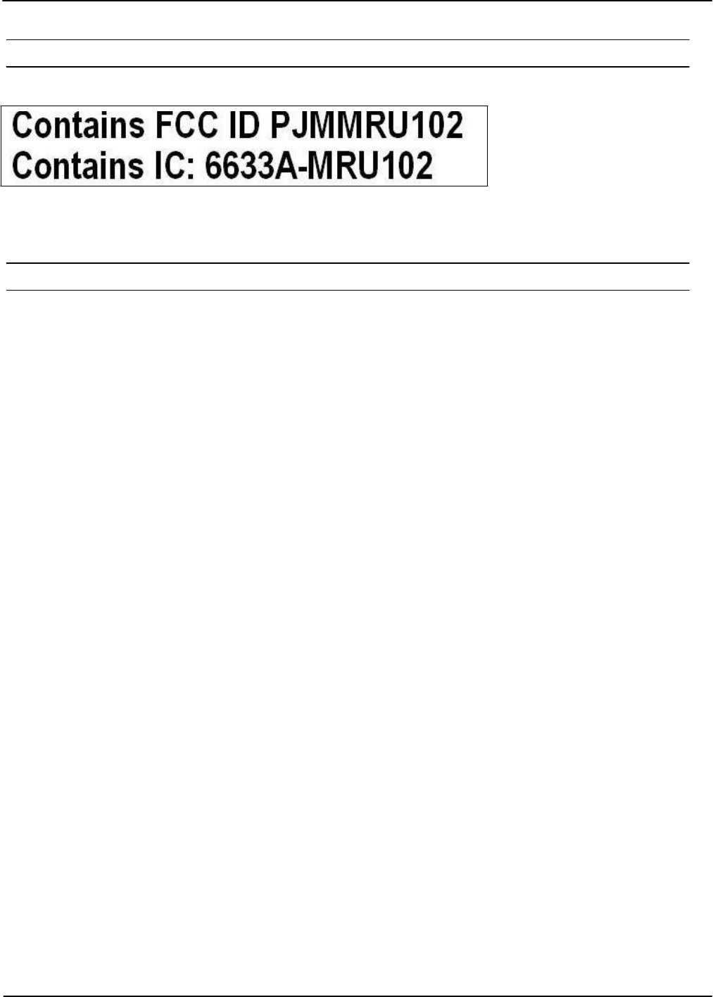
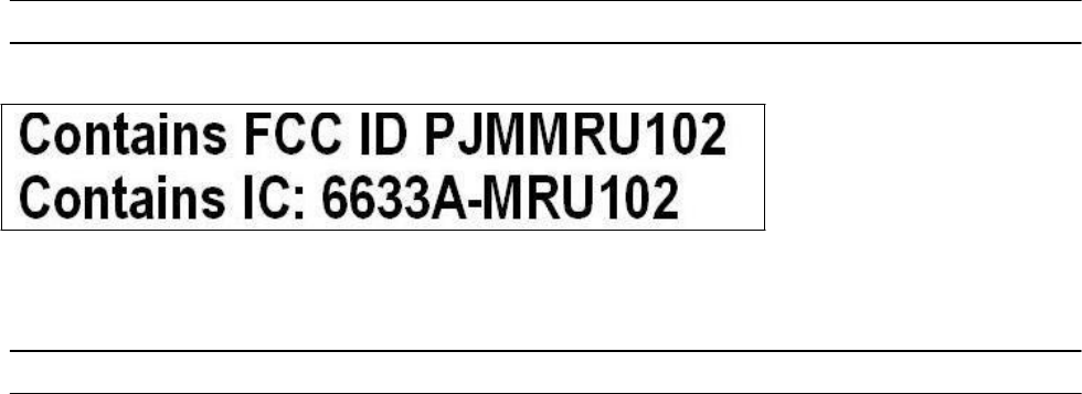
7.3.2. Label Information Reader Module ID ISC.MRMU102-A
The following information has to be mounted outside on the housing of the reader module.
7.3.3. USA (FCC) and Canada (IC) approved antennas
This radio transmitter (identify the device by certification number, or model number if Category II)
has been approved by Industry Canada to operate with the antenna types listed below with maxi-
mum permission gain and required antenna impedance for each antenna type indicated. Antenna
types, not included in this list, having a gain greater than the maximum gain indicated for that type,
are strictly prohibited for use with this device
Le présent émetteur radio (identifier le dispositif par son numéro de certification ou son numéro de
modèle s’il fait partie du matériel de catégorie I) a été approuvé par Industrie Canada pour fonc-
tionner avec les types d’antenne ’énoncé ci-dessus et ayant un gain admissible maximal et
l’impédance requise pour chaque type d’antenne. Les types d’antenne non inclus dans cette liste,
ou dont le gain est supérieur au gain maximal indiqué, sont strictement interdits pour l’exploitation
de l’émetteur
Following antennas are approved by FCC according FCC Part 15 and IC Canada according
RS210
•
ID ISC.ANT.U170/170 –FCC (4.0 dBic)
•
ID ISC.ANT.U270/270-FCC (9.0 dBic)
•
ID ISC.ANT.U600/270-FCC (11,0 dBic)
•
Integrated antenna (- 7dBic)

OBID
i-scan
®
UHF
Integration
ID ISC.MRMU102-A
FEIG ELECTRONIC GmbH Page 21 of 21 Integration Manual M21112-1e-
ID-B.docx
ANNEX A - Accessories
The following accessories are available for the Reader.
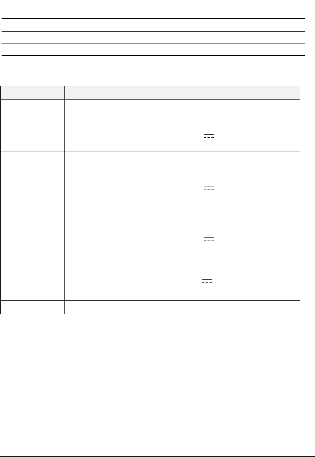
Article No. Part No. Description
1688.002.00 ID NET.12V-B-EU
Power Supply 95 - 265V AC Input Voltage,
(Continental European Plug),
with angular DC Plug 2,5mm*5,5mm
Output: 12 V DC/ ; 700mA
Ambient Operating Temperature: 0°C to +40°C
3886.000.00 ID NET.12V-B-GB
Power Supply 95 - 265V AC Input Voltage,
(GB/UK Plug),
with angular DC Plug 2,5mm*5,5mm
Output: 12 V DC/ ; 700mA
Ambient Operating Temperature: 0°C to +40°C
3887.000.00 ID NET.12V-B-US
Power Supply 95 - 265V AC Input Voltage,
(US Plug),
with angular DC Plug 2,5mm*5,5mm
Output: 12 V DC/ ; 700mA
Ambient Operating Temperature: 0°C to +40°C
1686.000.00 ID CAB.USB-A USB-cable 2,5m
1690.000.00 ID CAB.RS-A Serial data cable
Table 8: Accessories
MONTAGE
INSTALLATION
preliminary
public (B)
2012-03-22
M20110-1de-ID-B.doc
ID ISC.MRU102-PoE
ID ISC.MRU102-USB
Gehäuse-Variante
Housed Version


OBID
i-scan
®
Montage / Installation
ID ISC.MRU102
FEIG ELECTRONIC GmbH Seite 3 von 42 M20110-1de-ID-B.doc
Hinweis
Copyright 2012 by
FEIG ELECTRONIC GmbH
Lange Straße 4
D-35781 Weilburg
Tel.: +49 6471 3109-0
http://www.feig.de
Alle früheren Ausgaben verlieren mit dieser Ausgabe ihre Gültigkeit.
Die Angaben in diesem Dokument können ohne vorherige Ankündigung geändert werden.
Weitergabe sowie Vervielfältigung dieses Dokuments, Verwertung und Mitteilung ihres Inhalts sind nicht
gestattet, soweit nicht ausdrücklich zugestanden. Zuwiderhandlung verpflichtet zu Schadenersatz. Alle
Rechte für den Fall der Patenterteilung oder Gebrauchsmuster-Eintragung vorbehalten.
Die Zusammenstellung der Informationen in diesem Dokument erfolgt nach bestem Wissen und Gewissen.
FEIG ELECTRONIC GmbH übernimmt keine Gewährleistung für die Richtigkeit und Vollständigkeit der An-
gaben in diesem Dokument. Insbesondere kann FEIG ELECTRONIC GmbH nicht für Folgeschäden auf
Grund fehlerhafter oder unvollständiger Angaben haftbar gemacht werden. Da sich Fehler, trotz aller Bemü-
hungen nie vollständig vermeiden lassen, sind wir für Hinweise jederzeit dankbar.
Die in diesem Dokument gemachten Installationsempfehlungen gehen von günstigsten Rahmenbedingun-
gen aus. FEIG ELECTRONIC GmbH übernimmt weder Gewähr für die einwandfreie Funktion in system-
fremden Umgebungen, noch für die Funktion eines Gesamtsystems, welches die in diesem Dokument be-
schriebenen Geräte enthält.
FEIG ELECTRONIC weist ausdrücklich darauf hin, dass die in diesem Dokument beschriebenen Geräte
nicht für den Einsatz mit oder in medizinischen Geräten oder für Geräte für lebenserhaltende Maßnahmen
konzipiert sind, bei denen ein Fehler eine Gefahr für menschliches Leben oder für die gesundheitliche Un-
versehrtheit zur Folge haben kann. Der Applikationsdesigner ist dafür verantwortlich geeignete Maßnahmen
zu ergreifen um Gefahren, Schäden oder Verletzungen zu vermeiden.
FEIG ELECTRONIC GmbH übernimmt keine Gewährleistung dafür, dass die in diesem Dokument enthal-
tenden Informationen frei von fremden Schutzrechten sind. FEIG ELECTRONIC GmbH erteilt mit diesem
Dokument keine Lizenzen auf eigene oder fremde Patente oder andere Schutzrechte.
OBID® und OBID i-scan® ist ein eingetragenes Warenzeichen der FEIG ELECTRONIC GmbH.

OBID
i-scan
®
Montage / Installation
ID ISC.MRU102
FEIG ELECTRONIC GmbH Seite 4 von 42 M20110-1de-ID-B.doc
Inhalt
1 Sicherheits- und Warnhinweise - vor Inbetriebnahme unbedingt lesen 6
2 Leistungsmerkmale der Readerfamilie ID ISC.MRU102 7
2.1 Verfügbare Readertypen ............................................................................................ 7
2.2 Verfügbares Zubehör .................................................................................................. 7
3 Montage 8
3.1 Gehäusevariante ......................................................................................................... 8
3.2 Abmessungen ............................................................................................................. 8
4 Anschlüsse 9
4.1 Antennenanschluss ANT 1....................................................................................... 10
4.2 Interne Antenne ANT 4 ............................................................................................. 10
4.3 Versorgungsspannung ............................................................................................. 11
4.3.1 Spannungsversorgung über X1 .............................................................................. 11
4.3.2 Versorgungsspannung über PoE (Power over Ethernet) (ID ISC.MRU102-PoE) .... 12
4.4 Ethernet-Schnittstelle an X2 (10/100Tbase) ............................................................ 13
4.5 USB – Schnittstelle X3 (Host Kommunikation) ....................................................... 14
5 Bedien und Anzeigeelemente 15
5.1 LED ............................................................................................................................ 15
6 Technische Daten 16
7 Funk Zulassungen 18
7.1 Europa (CE) ............................................................................................................... 18
7.2 Declaration of Conformity ........................................................................................ 19

OBID
i-scan
®
Montage / Installation
ID ISC.MRU102
FEIG ELECTRONIC GmbH Seite 5 von 42 M20110-1de-ID-B.doc
8 Anhang 20
8.1 Zubehör ..................................................................................................................... 20
8.1.1 Wandmontagesatz ID ISC.MS.MR/PR-A ................................................................ 21

OBID
i-scan
®
Montage / Installation
ID ISC.MRU102
FEIG ELECTRONIC GmbH Seite 6 von 42 M20110-1de-ID-B.doc
1 Sicherheits- und Warnhinweise - vor Inbetriebnahme unbedingt lesen
• Das Gerät darf nur für den vom Hersteller vorgesehenen Zweck verwendet werden.
• Die Bedienungsanleitung ist zugriffsfähig aufzubewahren und jedem Benutzer auszuhändigen.
• Unzulässige Veränderungen und die Verwendung von Ersatzteilen und Zusatzeinrichtungen,
die nicht vom Hersteller des Gerätes verkauft oder empfohlen werden, können Brände, elektri-
sche Schläge und Verletzungen verursachen. Solche Maßnahmen führen daher zu einem
Ausschluß der Haftung und der Hersteller übernimmt keine Gewährleistung.
• Für das Gerät gelten die Gewährleistungsbestimmungen des Herstellers in der zum Zeitpunkt
des Kaufs gültigen Fassung. Für eine ungeeignete, falsche manuelle oder automatische Ein-
stellung von Parametern für ein Gerät bzw. ungeeignete Verwendung eines Gerätes wird keine
Haftung übernommen.
• Reparaturen dürfen nur vom Hersteller durchgeführt werden.
• Anschluß-, Inbetriebnahme-, Wartungs-, und sonstige Arbeiten am Gerät dürfen nur von Elekt-
rofachkräften mit einschlägiger Ausbildung erfolgen.
• Alle Arbeiten am Gerät und dessen Aufstellung müssen in Übereinstimmung mit den nationa-
len elektrischen Bestimmungen und den örtlichen Vorschriften durchgeführt werden.
• Beim Arbeiten an dem Gerät müssen die jeweils gültigen Sicherheitsvorschriften beachtet wer-
den.
• Besonderer Hinweis für Träger von Herzschrittmachern:
Obwohl dieses Gerät die zulässigen Grenzwerte für elektromagnetische Felder nicht über-
schreitet, sollten Sie einen Mindestabstand von 25 cm zwischen dem Gerät und Ihrem Herz-
schrittmacher einhalten und sich nicht für längere Zeit in unmittelbarer Nähe des Geräts bzw.
der Antenne aufhalten.

OBID
i-scan
®
Montage / Installation
ID ISC.MRU102
FEIG ELECTRONIC GmbH Seite 7 von 42 M20110-1de-ID-B.doc
2 Leistungsmerkmale der Readerfamilie ID ISC.MRU102
Der Reader ist für das Lesen von passiven Datenträgern, sogenannten „Smart Labels“, mit einer
Betriebsfrequenz im UHF Bereich zwischen 860 MHz und 960 MHz entwickelt. Es werden Trans-
ponder nach EPC Class1 Gen2 unterstützt. Optional kann eine Freischaltung zum Lesen von
Transpondern nach ISO 18000-6-C erfolgen. Der Leser ist konzipiert für Anwendungen mit gerin-
ger Transponderdichte.
Der Reader verfügt über einen externen Antennenanschluss über eine SMA Buchse (ANT1) und
eine interne Antenne (ANT 4). Die interne Antenne ist sowohl zum Lesen von Fernfeld- als auch
zum Lesen von Nahfeld-Transpondern geeignet.
Der Leser ist für die Nutzung in Applikationen mit geringer Transponderdichte konzipiert. Er ist in
der Lage maximal 10 Transponder, die sich gleichzeitig im Antennenfeld befinden, zu verarbeiten.
Es stehen zwei unterschiedliche Gerätevarianten zur Verfügung. Je nach Variante kann eine An-
bindung an ein Host-System über die Ethernet- oder die USB-Schnittstelle erfolgen.
2.1 Verfügbare Readertypen
Folgende Reader sind z.Z. verfügbar:
Readertyp Beschreibung
ID ISC.MRU102-PoE Gehäusevariante mit LAN Schnittstelle und Power over Ethernet
ID ISC.MRU102-USB Gehäusevariante mit USB-Schnittstelle
Tabelle 1: Readertypen
2.2 Verfügbares Zubehör
optionales Zubehör ist im Anhang aufgeführt:

OBID
i-scan
®
Montage / Installation
ID ISC.MRU102
FEIG ELECTRONIC GmbH Seite 8 von 42 M20110-1de-ID-B.doc
3 Montage
3.1 Gehäusevariante
Der Reader ist für Anwendungen im Innenbereich konzipiert. Eine Wandmontage ist mit dem op-
tional erhältlichen Wandmontagesatz möglich.
(Siehe Anhang Wandmontagesatz ID ISC.MS.MR/PR-A)
Hinweise:
• Vor der endgültigen Installation sollte der geplante Installationsort auf seine Taug-
lichkeit geprüft werden.
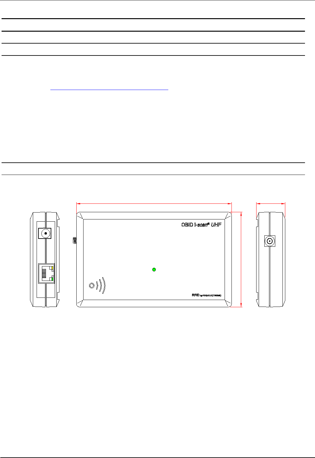
3.2 Abmessungen
145
85
LED
27
Abbildung 1: Abmessungen der Gehäusevariante (alle Maße in mm)
OBID
i-scan
®
Montage / Installation
ID ISC.MRU102
FEIG ELECTRONIC GmbH Seite 9 von 42 M20110-1de-ID-B.doc
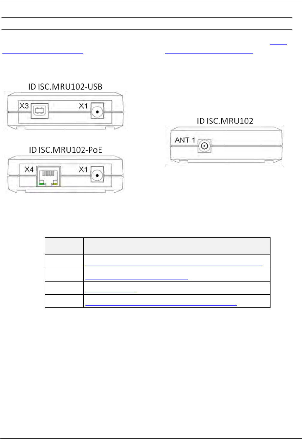
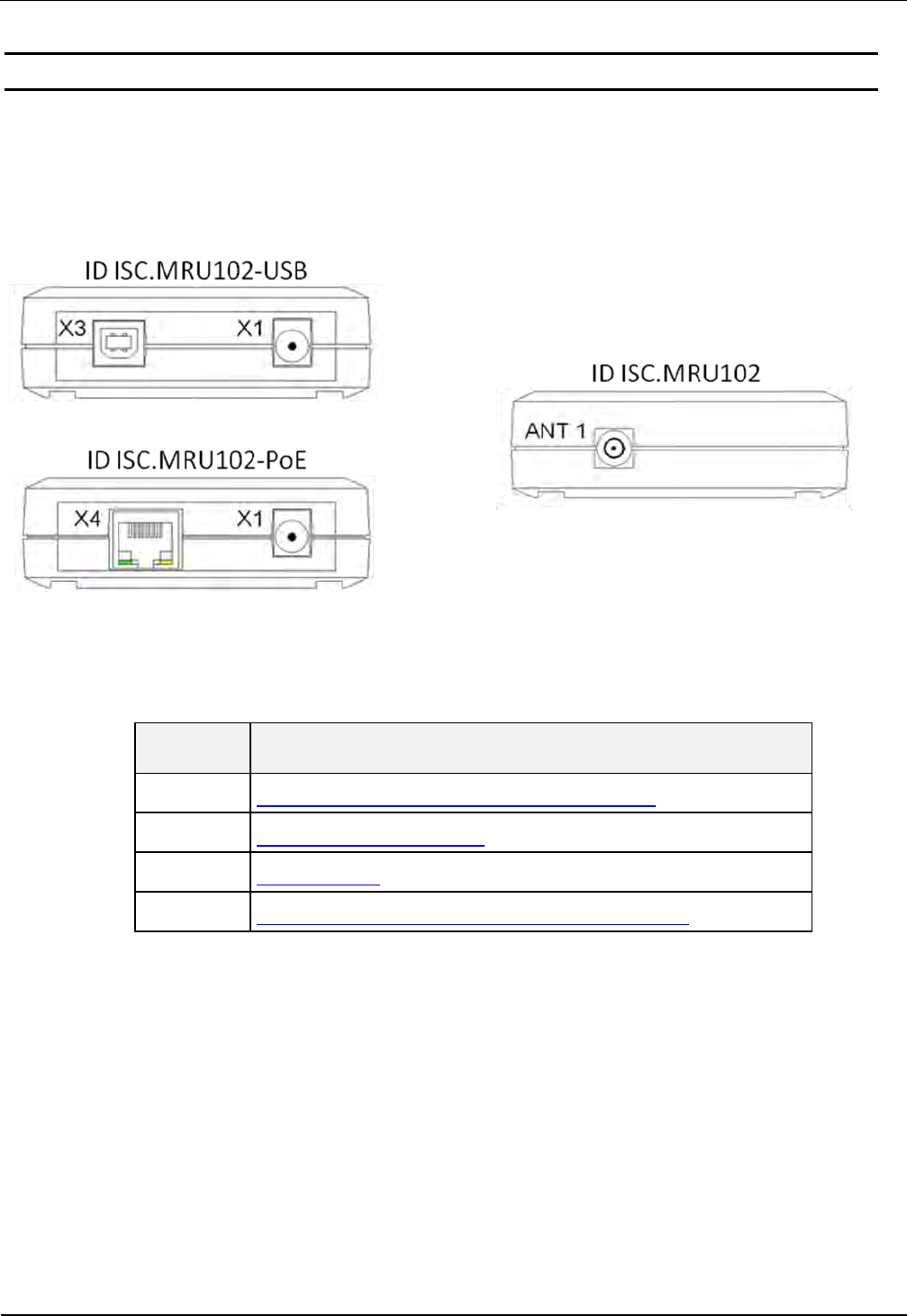
4 Anschlüsse
Je nach Variante des Readers stehen unterschiedliche Anschlussklemmen zur Verfügung. Abbil-
dung 3: Anschlussübersicht zeigt die Anordnung und in Tabelle 2: Anschlussklemmen ist darge-
stellt, welche Anschlüsse für die einzelnen Schnittstellenkabel verwendet werden sollen.
Abbildung 2: Anschlussübersicht
Anschluss Beschreibung
ANT 1 Anschluss einer externen Antenne (Eingangsimpedanz 50Ω)
X1 Versorgungsspannung 12 - 24VDC
X3 USB Schnittstelle
X4 10/100Tbase Netzwerkschnittstelle mit RJ-45 (PoE)
Tabelle 2: Anschlussklemmen
OBID
i-scan
®
Montage / Installation
ID ISC.MRU102
FEIG ELECTRONIC GmbH Seite 10 von 42 M20110-1de-ID-B.doc
4.1 Antennenanschluss ANT 1
Zum Anschluss der externen Antenne befindet sich auf der Leiterplatte eine SMA-Buchse (ANT1).
Das maximale Anzugsdrehmoment der SMA-Buchsen beträgt 0,45 Nm.
Achtung:
• Höhere Anzugsdrehmomente führen zur Zerstörung des Steckers.
Klemme Beschreibung
ANT 1 Anschluss der externen Antenne (Eingangsimpedanz 50 Ω)
Tabelle 3: Anschluss der externen Antenne
Hinweise:
• Beim Anschluss einer Antenne ist darauf zu achten, dass diese die zulässigen
Grenzwerte der nationalen Vorschriften bezüglich Funkanlagen nicht überschreitet.
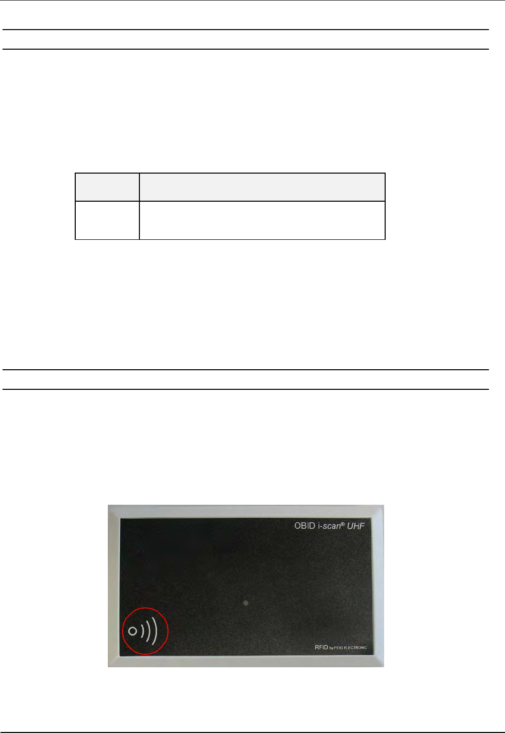
4.2 Interne Antenne ANT 4
Der Reader verfügt zusätzlich über eine bereits integrierte Antenne (ANT4). Die integrierte Anten-
ne ist sowohl zur Kommunikation mit Fernfeld- als auch mit Nahfeldtranspondern geeignet. Die
Antenne befindet sich in der unteren linken Ecke des Gehäuses und ist durch ein entsprechendes
Symbol gekennzeichnet. Die maximal mögliche Lesereichweite mit einem Fernfeldtransponder
beträgt ca. 40 cm. Mit einem Nahfeldtransponder können Lesereichweiten von maximal 5 cm er-
zielt werden.
Abbildung 3: Position der internen Antenne
OBID
i-scan
®
Montage / Installation
ID ISC.MRU102
FEIG ELECTRONIC GmbH Seite 11 von 42 M20110-1de-ID-B.doc
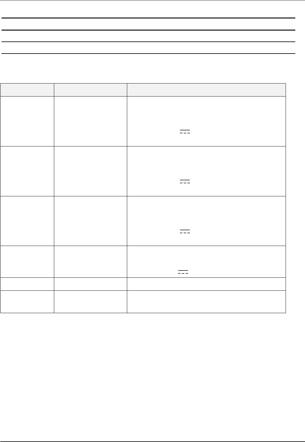
4.3 Versorgungsspannung
4.3.1 Spannungsversorgung über X1
Die Versorgungsspannung von 12 - 24 V DC ist an der Buchse X1 der Leiterplatte anzuschließen.
Buchse Kurzzeichen Beschreibung X 1
X1 / Innen Vcc Vcc – Versorgungsspannung (+)
X1 / Außen GND Ground – Versorgungsspannung (-)
Tabelle 4: Anschluss der Versorgungsspannung
Hinweis:
• Eine Verpolung der Versorgungsspannung kann zur Zerstörung des Gerätes führen.
• Das Gerät sollte nur durch ein gelistetes NEC Class 2/LPS Netzteil versorgt werden.
Netzteilempfehlungen :
Zur Ausnutzung der vollständigen Leistungsfähigkeit des Readers sollte auf eine ausreichend sta-
bilisierte und rauscharme Spannungsversorgung geachtet werden. Bei der Verwendung eines
Schaltnetzteils ist darauf zu achten, dass die interne Schaltfrequenz des Netzteils unterhalb von
300 kHz liegt.(Siehe: Zubehör)
Feig Artikel Nr. Bezeichnung Beschreibung
1688.002.00 ID NET.12V-B-EU Netzteil 95 - 265V AC Eingangsspannung,
mit abgewinkelten DC Stecker 2,5mm*5,5mm
Output: 12 V DC/ ; 700mA
Umgebungstemperatur: 0°C bis +40°C
3886.000.00 ID NET.12V-B-GB
3887.000.00 ID NET.12V-B-US
Tabelle 5: Empfohlenes Netzteil
Hinweis:
• Das Netzteil wird mit einem DC-Stecker 2,5mm*5,5mm geliefert. Dieser ist passend
für die Buchse X1 des Readers.
OBID
i-scan
®
Montage / Installation
ID ISC.MRU102
FEIG ELECTRONIC GmbH Seite 12 von 42 M20110-1de-ID-B.doc
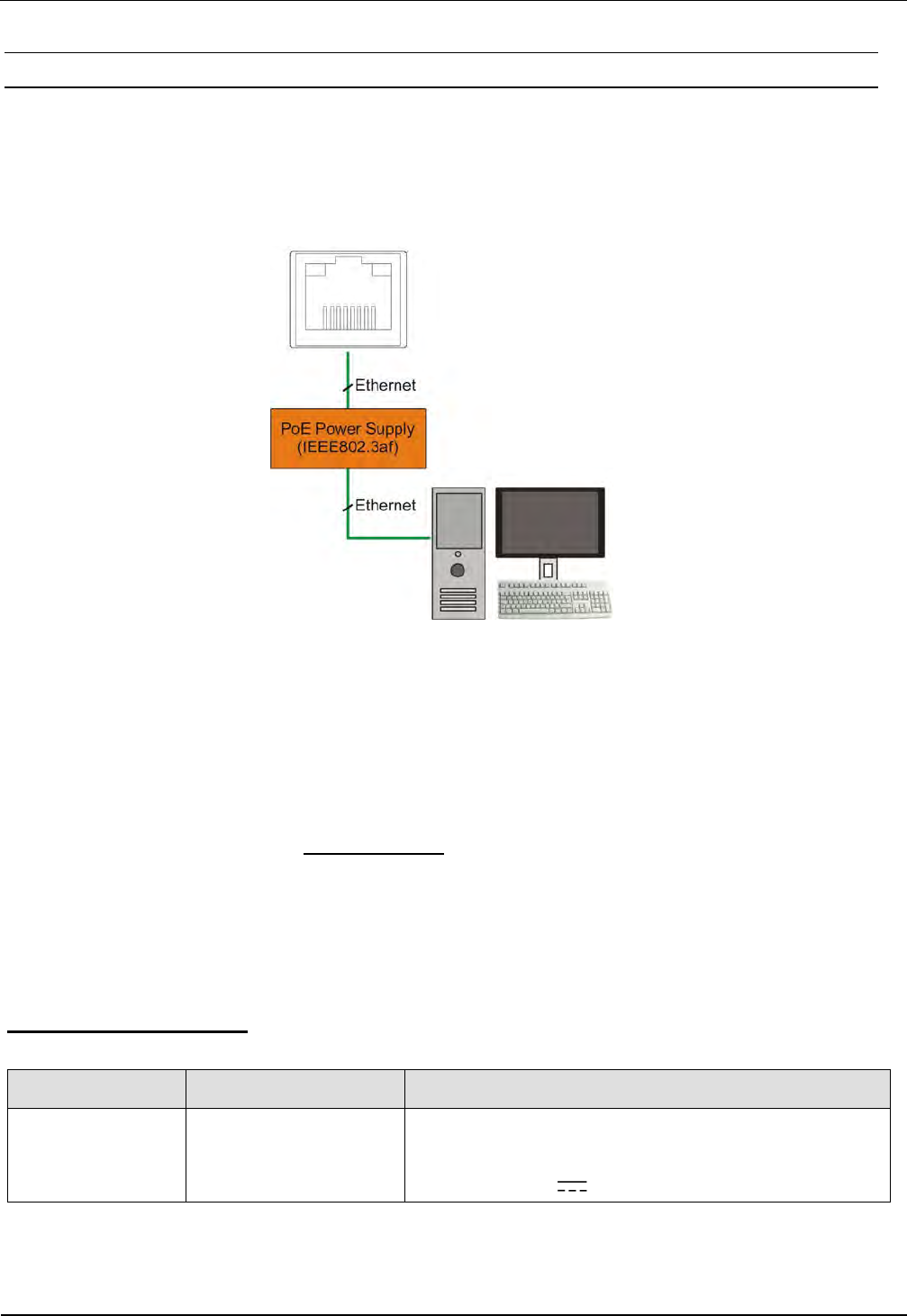
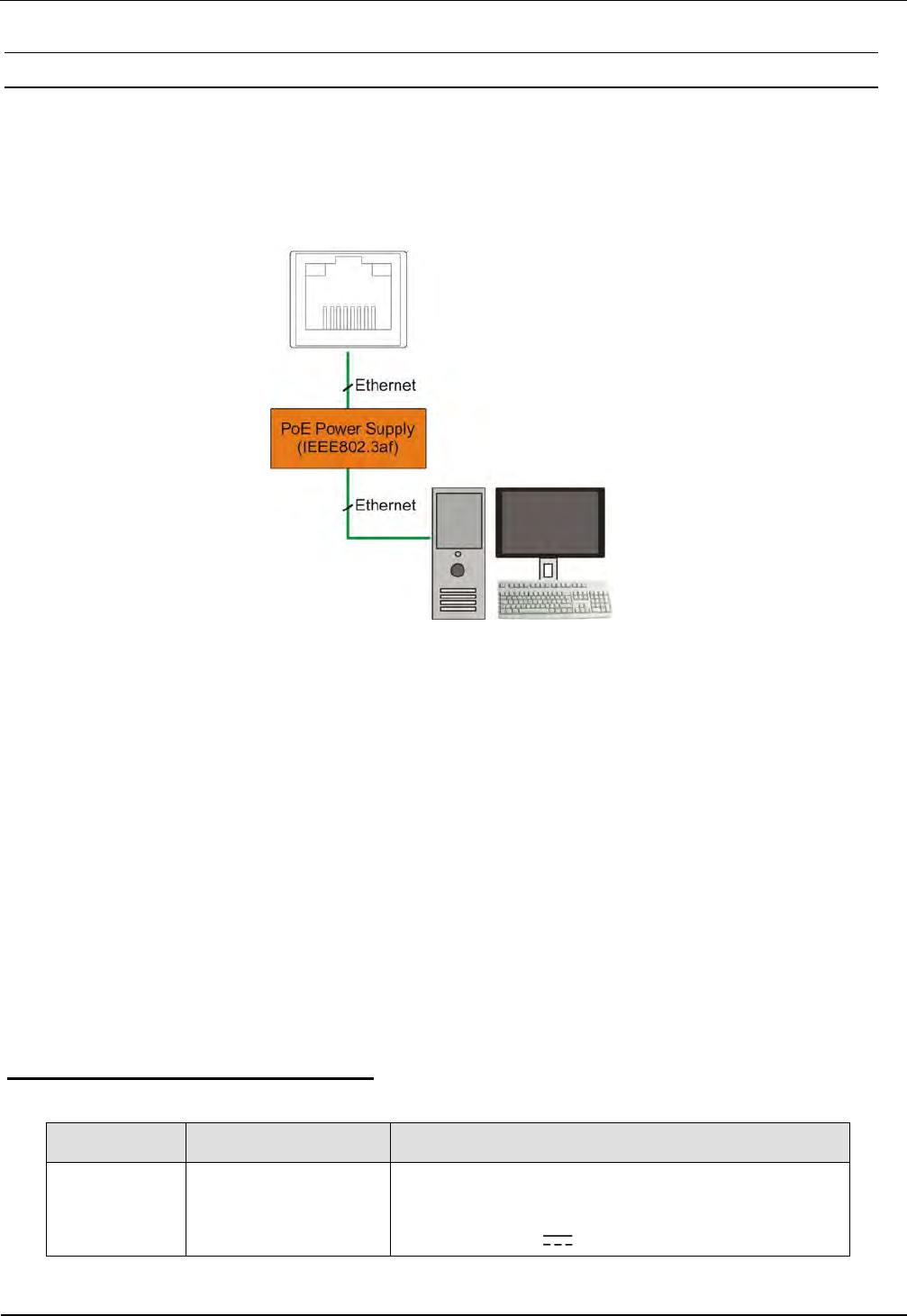
4.3.2 Versorgungsspannung über PoE (Power over Ethernet) (ID ISC.MRU102-PoE)
Alternativ kann die PoE Variante über den LAN-Anschluss X4 mit Hilfe eines „Power over Ether-
net“-Netzteil gem. IEEE802.3af*, Class2 (6,49 Watt) versorgt werden. Die DC Speisung kann über
die freien Pin’s 4,5 und 7,8 erfolgen (Midspan-Power), als auch eine „Phantomspeisung“ über die
Signalverbindung 1,2,3 und 6 ist möglich (Inline-Power).
Abbildung 4: LAN und PoE Anschluss
Hinweis
• Es ist sicherzustellen das der Reader mit mindestens 42,5 V (48 VDC – Leitungsver-
luste) versorgt wird.
• Die max. Leitungslänge für Ethernet ist 100m.
• Es wird empfohlen ein abgeschirmtes STP (shielded twisted pair) CAT5 Kabel zu
verwenden.
* Detaillierte technische Informationen zu dem Standard 802.3af können der aktuellen Version der
entsprechenden IEEE Spezifikation entnommen werden.
PoE-.Netzteilempfehlung:
Feig Artikel Nr. Bezeichnung Beschreibung
3842.000.00 ID NET.PoEI13W-A Power over Ethernet Netzteil 100-240V AC
(Continental European Plug),
Output: 48V DC/ ; 0,5A
Tabelle 6: Empfohlenes PoE-Netzteil
X4

OBID
i-scan
®
Montage / Installation
ID ISC.MRU102
FEIG ELECTRONIC GmbH Seite 13 von 42 M20110-1de-ID-B.doc
4.4 Ethernet-Schnittstelle an X2 (10/100Tbase)
Der Reader verfügt über eine integrierte 10/100 base-T Netzwerkschnittstelle mit Standard RJ-45-
Anschluss. Der Anschluss erfolgt über X2 und hat eine automatische „Crossover Detection“ ent-
sprechend dem 1000BASE-T Standard.
Bei einer strukturierten Verkabelung sollten mindestens Kabel der Kategorie CAT5 verwendet wer-
den. Dies garantiert einen problemlosen Betrieb bei 10 Mbps oder 100 Mbps.
Vorraussetzung für den Einsatz des TCP/IP-Protokolls ist, dass jedes Gerät am Netzwerk über
eine eigene IP-Adresse verfügt. Alle Reader verfügen über eine werksseitig voreingestellte IP-
Adresse. Die Übertragungsparameter können per Softwareprotokoll konfiguriert werden.
Netzwerk Adresse
IP-Adresse 192.168.10.10
Subnet-Mask 255.255.255.0
Port 10001
DHCP AUS
Tabelle 7: Werkskonfiguration der Ethernet-Schnittstelle
Hinweis:
• Der Reader verfügt über eine DHCP-fähige TCP/IP Schnittstelle.
• Es wird empfohlen ein abgeschirmtes STP (shielded twisted pair) CAT5 Kabel zu
verwenden.

OBID
i-scan
®
Montage / Installation
ID ISC.MRU102
FEIG ELECTRONIC GmbH Seite 14 von 42 M20110-1de-ID-B.doc
4.5 USB – Schnittstelle X3 (Host Kommunikation)
Der Anschluss der USB-Schnittstelle erfolgt über die Buchse X3. Die Belegung ist genormt. Die
Daten-rate des Readers ist auf 12 Mbit beschränkt (USB Full Speed). Es kann ein Standard-USB-
Kabel verwendet werden.
Hinweis:
• Die maximale Länge des USB-Kabels darf 5 m betragen. Längere Kabel sind nicht er-
laubt.
• Auch bei Verwendung der USB-Schnittstelle an einem „High Powered Port“ muss der
Reader mit einem externen Netzteil versorgt werden.
Abbildung
5: USB-Schnittstelle für Host Kommunikation

OBID
i-scan
®
Montage / Installation
ID ISC.MRU102
FEIG ELECTRONIC GmbH Seite 15 von 42 M20110-1de-ID-B.doc
5 Bedien und Anzeigeelemente
5.1 LED
Die LED des Readers kann per Software konfiguriert werden.
Die folgende Tabelle 8 zeigt die Werkseinstellung.
Kurzzeichen Beschreibung
LED grün "RUN "
- Leuchtet, wenn der Reader betriebsbereit ist.
LED rot
„TRANSPONDER“
- Leuchtet, wenn ein Transponder erkannt wird.
- Blinkt bei RF-Warning (rot - grün abwechselnd mit 8Hz)
(Temperaturalarm, Kurzschluss am Antennenausgang)
LED orange
„INITIALISIERUNG“
- Blinkt während der Reader-Initialisierung nach dem Ein-
schalten.
Tabelle 8: Standard-Konfiguration der LED

OBID
i-scan
®
Montage / Installation
ID ISC.MRU102
FEIG ELECTRONIC GmbH Seite 16 von 42 M20110-1de-ID-B.doc
6 Technische Daten
Mechanische Daten
• Gehäuse
Kunststoff ABS geschlossen
• Abmessungen ( B x H x T )
145 mm x 85 mm x 27 mm
• Gewicht
200 g
• Schutzart
IP 30
• Farbe
ähnlich RAL 9018 (Papyrusweiß)
Elektrische Daten
• Spannungsversorgung
– ID ISC.MRU102-USB
– ID ISC.MRU102-PoE
12 V DC bis 24 V DC
12 V DC bis 24 V DC oder PoE
• Leistungsaufnahme
max. 7 W
• Betriebsfrequenz
860 MHz bis 960 MHz
• Sendeleistung
max. 500 mW ± 1,5 dB
• Antennenanschluss
1 x SMA Buchse (50Ω)
1 x interne Antenne (ANT4)
• Schnittstellen
– ID ISC.MRU102-PoE
– ID ISC.MRU102-USB
Ethernet (TCP/IP)
USB (Full Speed)
• Sonstiges
Anticollision,
RSSI,
Temperaturüberwachung*
Funktionelle Eigenschaften
• Protokoll Modi
FEIG ISO HOST (Advanced Protocol Frame)
Scan Mode (nur ID ISC.MRU102-USB, HID
Mode)
Notification Mode (nur ID ISC.MRU102-PoE)
• Unterstützte Transponder
EPC Class1 Gen2
ISO 18000-6-C (Freischaltcode erforderlich)
• Signalgeber optisch
1 LED ( mehrfarbig – rot / grün)
* Achtung: Eine Überhitzung des Gerätes kann zu Leistungseinbußen führen. Um dies auszuschließen wird empfohlen die RF des Lesers nur
dann zu aktivieren, wenn sich ein Transponder im Erfassungsbereich einer Antenne befindet.

OBID
i-scan
®
Montage / Installation
ID ISC.MRU102
FEIG ELECTRONIC GmbH Seite 17 von 42 M20110-1de-ID-B.doc
Umgebungsbedingungen
• Temperaturbereich
- Betrieb
- Lagerung
-25 °C bis +55 °C (-USB)
-25 °C bis +45 °C (-PoE)
-25 °C bis +85 °C
• Relative Luftfeuchtigkeit
5 % bis 95 % nicht betauend
Angewendete Normen
• Zulassung Funk
- Europa
- USA
- Kanada
EN 302 208
FCC 47 CFR Part 15
IC RSS-Gen, RSS-210
• EMV
EN 301 489
• Vibration
EN60068-2-6
10 Hz bis 150 Hz : 0,075 mm / 1 g
• Schock
EN60068-2-27
Beschleunigung : 30 g

OBID
i-scan
®
Montage / Installation
ID ISC.MRU102
FEIG ELECTRONIC GmbH Seite 18 von 42 M20110-1de-ID-B.doc
7 Funk Zulassungen
7.1 Europa (CE)
Die Funkanlage entspricht, bei bestimmungsgemäßer Verwendung den grundlegenden Anforde-
rungen des Artikels 3 und den übrigen einschlägigen Bestimmungen der R&TTE Richtlinie
1999/5/EG vom März 1999.
Equipment Classification gemäß ETSI EN 301 489: Class 2

OBID
i-scan
®
Montage / Installation
ID ISC.MRU102
FEIG ELECTRONIC GmbH Seite 19 von 42 M20110-1de-ID-B.doc
7.2 Declaration of Conformity
OBID
i-scan
®
Montage / Installation
ID ISC.MRU102
FEIG ELECTRONIC GmbH Seite 20 von 42 M20110-1de-ID-B.doc
8 Anhang
8.1 Zubehör
Zu dem Reader ist folgendes Zubehör zu erhalten.
Artikel Nr.
Bezeichnung
Beschreibung
1688.002.00 ID NET.12V-B-EU
Netzteil 95 - 265V AC Eingangsspannung,
(Continental European Plug),
mit abgewinkelten DC Stecker 2,5mm*5,5mm
Output: 12 V DC/ ; 700mA
Umgebungstemperatur: 0°C bis +40°C
3886.000.00 ID NET.12V-B-GB
Netzteil 95 - 265V AC Eingangsspannung,
(GB/UK Plug),
mit abgewinkelten DC Stecker 2,5mm*5,5mm
Output: 12 V DC/ ; 700mA
Umgebungstemperatur: 0°C bis +40°C
3887.000.00 ID NET.12V-B-US
Netzteil 95 - 265V AC Eingangsspannung,
(US Plug),
mit abgewinkelten DC Stecker 2,5mm*5,5mm
Output: 12 V DC/ ; 700mA
Umgebungstemperatur: 0°C bis +40°C
3842.000.00 ID NET.PoEI13W-A
Power over Ethernet Netzteil 100-240V AC
(Continental European Plug),
Output: 48V DC/ ; 0,5A
1686.000.00 ID CAB.USB-A USB-Kabel 2,5m
1691.000.01 ID ISC.MS.MR/PR-A Wandmontagesatz für ID ISC.MR102
Tabelle 9: Zubehör
OBID
i-scan
®
Montage / Installation
ID ISC.MRU102
FEIG ELECTRONIC GmbH Seite 21 von 42 M20110-1de-ID-B.doc
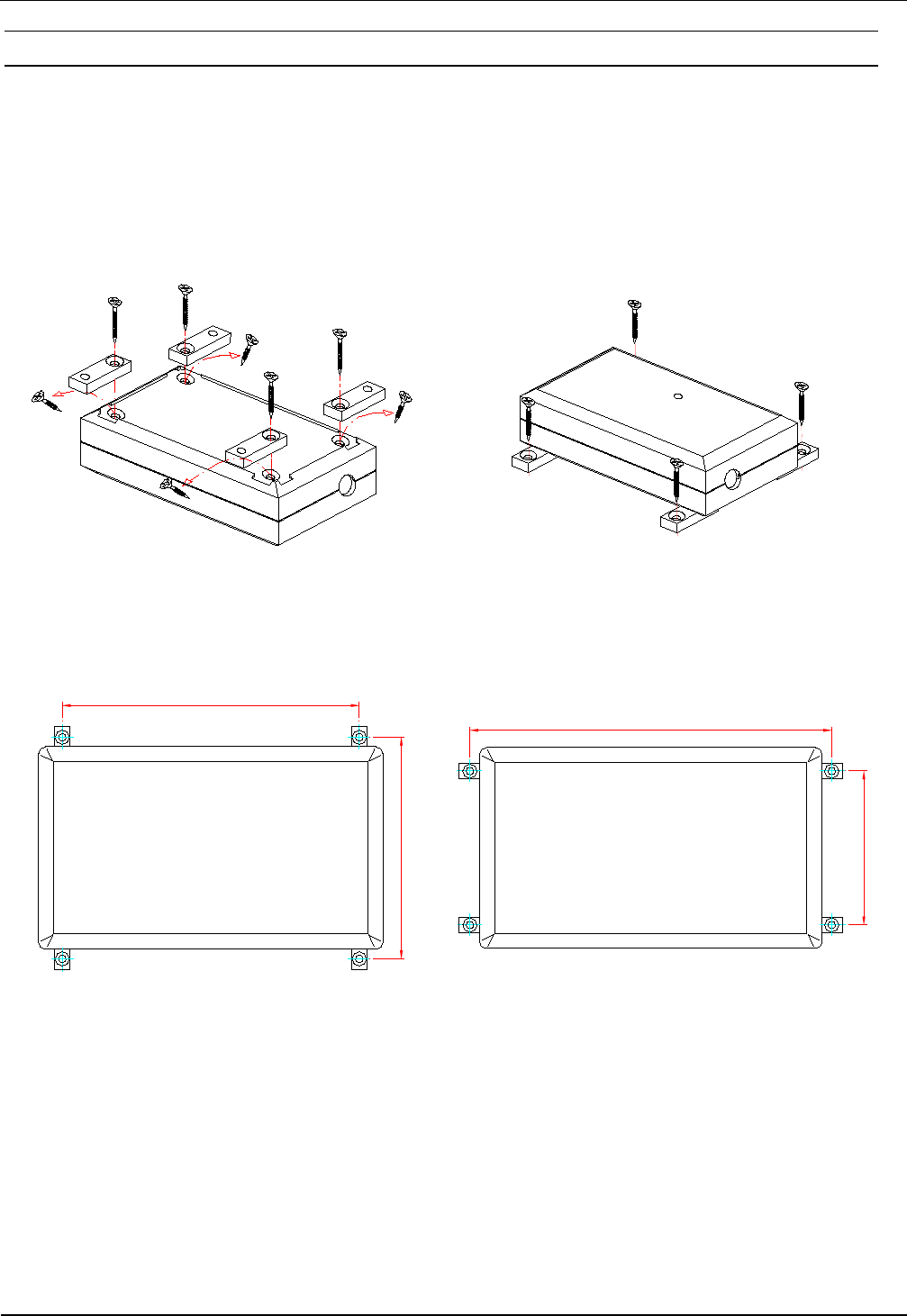
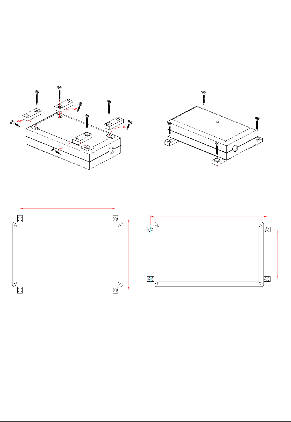
8.1.1 Wandmontagesatz ID ISC.MS.MR/PR-A
Mit Hilfe des Wandmontagesatzes kann der Reader auf einer ebenen Fläche befestigt werden.
• Die Schrauben auf der Rückseite des Readers entfernen.
• Die einzelnen Wandhalter mit denen im Montagesatz beigefügten Schrauben befestigen.
Abbildung 6: Montage Wandhalter
93
125
153
65
Abbildung 7: Montage - Bohrmaße (alle Maße in mm)

OBID
i-scan
®
Montage / Installation
ID ISC.MRU102
FEIG ELECTRONIC GmbH Seite 22 von 42 M20110-1de-ID-B.doc

OBID
i-scan
®
Montage / Installation
ID ISC.MRU102
FEIG ELECTRONIC GmbH Seite 23 von 42 M20110-1de-ID-B.doc
Note
Copyright 2012 by
FEIG ELECTRONIC GmbH
Lange Strasse 4
D-35781 Weilburg
Tel.: +49 6471 3109-0
http://www.feig.de
With the edition of this document, all previous editions become void. Indications made in this manual may be
changed without previous notice.
Copying of this document, and giving it to others and the use or communication of the contents thereof are
forbidden without express authority. Offenders are liable to the payment of damages. All rights are reserved
in the event of the grant of a patent or the registration of a utility model or design.
Composition of the information in this document has been done to the best of our knowledge. FEIG
ELECTRONIC GmbH does not guarantee the correctness and completeness of the details given in this
manual and may not be held liable for damages ensuing from incorrect or incomplete information. Since,
despite all our efforts, errors may not be completely avoided, we are always grateful for your useful tips.
The instructions given in this manual are based on advantageous boundary conditions. FEIG ELECTRONIC
GmbH does not give any guarantee promise for perfect function in cross environments.
FEIG call explicit attention that devices which are subject of this document are not designed with compo-
nents and testing methods for a level of reliability suitable for use in or in connection with surgical implants or
as critical components in any life support systems whose failure to perform can reasonably be expected to
cause significant injury to a human. To avoid damage, injury, or death, the user or application designer must
take reasonably prudent steps to protect against system failures.
FEIG ELECTRONIC GmbH assumes no responsibility for the use of any information contained in this docu-
ment and makes no representation that they free of patent infringement. FEIG ELECTRONIC GmbH does
not convey any license under its patent rights nor the rights of others.
OBID® and OBID i-scan® are registered trademarks of FEIG ELECTRONIC GmbH.

OBID
i-scan
®
Montage / Installation
ID ISC.MRU102
FEIG ELECTRONIC GmbH Seite 24 von 42 M20110-1de-ID-B.doc
Contents
9 Safety Instructions / Warning - Read before start-up ! 26
10 Performance Features of the readers 27
10.1 Available Reader types ............................................................................................. 27
10.2 Optional accessories ................................................................................................ 27
11 Assembly and Wiring 28
11.1 Housed versions ....................................................................................................... 28
11.1.1 Dimensions ............................................................................................................ 28
12 Connections 29
12.1 Antenna Terminal ANT 1 .......................................................................................... 30
12.2 Internal Antenna ANT4 ............................................................................................. 30
12.3 Power supply ............................................................................................................ 31
12.3.1 Power supply via X1 ............................................................................................... 31
12.3.2 Power supply via PoE (Power over Ethernet) on X4 (ID ISC.MRU102-PoE) .......... 32
12.4 Ethernet-Interface on X4 (10/100Tbase) .................................................................. 33
12.5 USB – Interface X3 (Host communication) .............................................................. 34
13 Control and display elements LED 35
13.1 LED ............................................................................................................................ 35
14 Technical Data 36
15 Radio Approvals 38
15.1 Europe (CE) ............................................................................................................... 38
15.2 Declaration of Conformity ........................................................................................ 39
15.3 USA (FCC) and Canada (IC) ..................................................................................... 40

OBID
i-scan
®
Montage / Installation
ID ISC.MRU102
FEIG ELECTRONIC GmbH Seite 25 von 42 M20110-1de-ID-B.doc
16 Annex 41
16.1 Accessories .............................................................................................................. 41
16.1.1 Wall mounting kit ID ISC.MS.MR/PR-A .................................................................. 42

OBID
i-scan
®
Montage / Installation
ID ISC.MRU102
FEIG ELECTRONIC GmbH Seite 26 von 42 M20110-1de-ID-B.doc
9 Safety Instructions / Warning - Read before start-up !
• The device may only be used for the purpose intended by the manufacturer.
• The operation manual should be kept readily available at all times for each user.
• Unauthorized changes and the use of spare parts and additional devices which have not been
sold or recommended by the manufacturer may cause fire, electric shocks or injuries. Such
unauthorized measures shall exclude the manufacturer from any liability.
• The liability-prescriptions of the manufacturer in the issue valid at the time of purchase are valid
for the device. The manufacturer shall not be held legally responsible for inaccuracies, errors,
or omissions in the manual or automatically set parameters for a device or for an incorrect
application of a device.
• Repairs may only be undertaken by the manufacturer.
• Installation, operation, and maintenance procedures should only be carried out by qualified
personnel.
• Use of the device and its installation must be in accordance with national legal requirements
and local electrical codes .
• When working on devices the valid safety regulations must be observed.
• Before touching the device, the power supply must always be interrupted. Make sure that the
device is without voltage by measuring. The fading of an operation control (LED) is no indicator
for an interrupted power supply or the device being out of voltage!
• Special advice for wearers of cardiac pacemakers:
Although this device doesn't exceed the valid limits for electromagnetic fields you should keep
a minimum distance of 25 cm between the device and your cardiac pacemaker and not stay in
the immediate proximity of the device’s antenna for any length of time.

OBID
i-scan
®
Montage / Installation
ID ISC.MRU102
FEIG ELECTRONIC GmbH Seite 27 von 42 M20110-1de-ID-B.doc
10 Performance Features of the readers
The Reader ID ISC.MRU102 is designed for reading of passive data carriers, so-called „Smart La-
bels“ at an operating frequency in the UHF band between 860 MHz and 960 MHz. Transponders
according to EPC Class1 Gen2 are supported. Optional an Upgrade Code for the reading of ISO
18000-6-C transponders is available. The reader is designed for application with small tag popula-
tion.
The reader is equipped with 1 SMA connector for conduction of an external antenna (ANT1). Addi-
tional an integrated antenna (ANT4) is available.
The reader is designed for use in applications with small tag populations. Maximum 10 tags at the
same time into the antenna field can be processed.
The reader is available in two different versions. Depending on the used version a connection to
the Host-System can either be made via the USB or the Ethernet Interface.
10.1 Available Reader types
The following reader types are currently available:
Reader type Description
ID ISC.MRU102-PoE Housed version with LAN Interface and Power over Ethernet (PoE)
ID ISC.MRU102-USB Housed version with USB Interface
Table 1: Reader types
10.2 Optional accessories
Optional Accessories are listed in the attachment.
OBID
i-scan
®
Montage / Installation
ID ISC.MRU102
FEIG ELECTRONIC GmbH Seite 28 von 42 M20110-1de-ID-B.doc
11 Assembly and Wiring
11.1 Housed versions
The Reader is designed for an office environment. It can be wall-mounted, in this case the wall-
mount kit should be ordered separately.
(see Appendix: Wall mounting kit ID ISC.MS.MR/PR-A)
Notes:
• Before any installation the intended position of the reader should be tested for its
suitability.
11.1.1 Dimensions
145
85
LED
27
Figure 1: Dimensions of the housing version (all dimensions are in mm)
OBID
i-scan
®
Montage / Installation
ID ISC.MRU102
FEIG ELECTRONIC GmbH Seite 29 von 42 M20110-1de-ID-B.doc
12 Connections
Depending on the reader variant different connectors are available. Figure 3: Connection overview
displays the arrangement and the Table 2: Connectors shows which connector can be used for the
different interface cable.
Figure 2: Connection overview
Connector Description
ANT 1 Antenna terminal ANT 1 (Impedance 50Ohm)
X1 Power supply 12 - 24VDC
X3 USB Interface
X4 10/100Tbase Ethernet interface with RJ-45 (PoE)
Table 2: Connectors
OBID
i-scan
®
Montage / Installation
ID ISC.MRU102
FEIG ELECTRONIC GmbH Seite 30 von 42 M20110-1de-ID-B.doc
12.1 Antenna Terminal ANT 1
A SMA socket (ANT1) is provided on the circuit board for connecting the external antenna. The
maximum tightening torque for the SMA socket is 0.45 Nm.
Caution:
• Higher tightening torque will damage the connector.
Terminal Description
ANT1 Connecting the external antenna
(input impedance 50Ω)
Table 3: Connecting the external antenna
Note:
• When connecting an antenna, ensure that it does not exceed the permissible limits
pre-scribed by the national regulations for radio frequency devices.
12.2 Internal Antenna ANT4
Additionally the reader is equipped with an internal antenna (ANT4). The internal antenna supports
far field transponders as well as near field transponders. The internal antenna is located in the bot-
tom left corner of the housing and is marked with an antenna symbol. The maximum read range of
the antenna in combination with a far field transponder is approx. 40 cm. In combination with a
near field transponder the maximum read range is approx. 5 cm.
Figure 3: Position of the internal antenna
OBID
i-scan
®
Montage / Installation
ID ISC.MRU102
FEIG ELECTRONIC GmbH Seite 31 von 42 M20110-1de-ID-B.doc
12.3 Power supply
12.3.1 Power supply via X1
Connect the 12 - 24 V DC/ supply voltage to socket X1 on the circuit board.
Terminal Name Description X 1
X1 / inside Vcc Vcc – supply voltage (+)
X1 / outside GND Ground – supply voltage (-)
Table 4: Connecting the supply voltage
Note:
• Reversing the polarity of the supply voltage may destroy the device.
• The unit has to supplied by a listed NEC Class 2/LPS Power supply, only
Power supply recommendations:
To take full advantage of the Reader performance, you must use a sufficiently regulated and low-
noise power supply. When using a switching power supply, be sure that its internal switching fre-
quency is less than 300 kHz. See also: Accessories
Feig Article No Part No. Description.
1688.002.00 ID NET.12V-B-EU Power Supply 95 - 265V AC Input Voltage,
with angular DC Plug 2,5mm*5,5mm
Output: 12 V DC/ ; 700mA
Ambient Operating Temperature: 0°C to +40°C
3886.000.00 ID NET.12V-B-GB
3887.000.00 ID NET.12V-B-US
Table 5: Recommended power supply
Note:
• The power supply is supplied with a DC/ plug 2.5mm x 5.5mm. This is compatible
with the readers socket X1.
OBID
i-scan
®
Montage / Installation
ID ISC.MRU102
FEIG ELECTRONIC GmbH Seite 32 von 42 M20110-1de-ID-B.doc
12.3.2 Power supply via PoE (Power over Ethernet) on X4 (ID ISC.MRU102-PoE)
Optional the reader (only MRU102-PoE) can be powered via the LAN connector on X4 with the use
of a PoE „Power over Ethernet“ power supply according to IEEE802.3af*, Class2 (6,49 Watt).
The DC supply can be achieved via the free pin’s 4,5 and 7,8 (Midspan-Power). Also a “Phantom
Powering” (Inline-Power) via the signal pin’s 1,2,3,and 6 is possible.
Figure 4: LAN and PoE connection
Note:
• It must be ensured that the reader is supplied with 42,5 V DC (48 V DC – cable losses) at
least.
• The maximum cable distance for Ethernet is 100m.
• A connection of the PoE Port X4 to devices at outside building installation (e.g. con-
nected to the outside plants) is not allowed.
• It is recommended to use a shielded twisted pair STP CAT5 cable.
* For detailed technical information regarding the 802.3af standard, please refer to the most
recent edition of the corresponding IEEE specification.
PoE - power supply recommendations:
Article No. Name Description
3842.000.00 ID NET.PoEI13W-A
Power over Ethernet Supply 100-240V AC
(Continental European Plug),
Output: 48V DC/ ; 0,5A
Table 6: Recommended PoE Power Supply
X4

OBID
i-scan
®
Montage / Installation
ID ISC.MRU102
FEIG ELECTRONIC GmbH Seite 33 von 42 M20110-1de-ID-B.doc
12.4 Ethernet-Interface on X4 (10/100Tbase)
The Reader has an integrated 10 / 100 base-T network port for an RJ-45. Connection is made on
X4 and has an automatic “Crossover Detection” according to the 100BASE-T Standard.
With structured cabling CAT 5 cables should be used. This ensures a reliable operation at 10 Mbps
or 100 Mbps.
The prerequisite for using TCP/IP protocol is that each device has a unique address on the net-
work. All Readers have a factory set IP address. Interface parameter can be configured via soft-
ware protocol (e.g. ISOStart).
Network Address
IP-Address 192.168.10.10
Subnet-Mask 255.255.255.0
Port 10001
DHCP OFF
Table 7: Standard factory configuration of the Ethernet connection
Note:
• The reader provides a DHCP able TCP/IP interface.
• It is recommended to use a shielded twisted pair STP CAT5 cable.

OBID
i-scan
®
Montage / Installation
ID ISC.MRU102
FEIG ELECTRONIC GmbH Seite 34 von 42 M20110-1de-ID-B.doc
12.5 USB – Interface X3 (Host communication)
There is a USB-socket X3 on board for the connection of the USB-Interface. The pinout is standar-
dized. The data rate is reduced to 12 Mbit (USB full speed). A standard USB-cable can be used.
Note:
• The length of the USB-cable can be a max. of 5 meter. It isn’t allowed to use longer
cables!
• The reader must be powered with a external power supply even if it is connected to a
“high powered port”.
Figure
5: USB interface for host communication

OBID
i-scan
®
Montage / Installation
ID ISC.MRU102
FEIG ELECTRONIC GmbH Seite 35 von 42 M20110-1de-ID-B.doc
13 Control and display elements LED
13.1 LED
The Reader’s LED can be configured through software.
The following Table 8 shows the default setting.
Abbreviation Description
LED green "RUN "
- Turns on when the Reader is ready
LED red
„LABEL“
- Turns on when a transponder is detected.
- Flashes if RF-Warning (red – green alternating with 8Hz)
(Temperature alarm, short circuit on antenna output)
LED orange „INITIALIZING“
- Flashes during Reader initialization after power-up.
Table 8: Default configuration of the LEDs

OBID
i-scan
®
Montage / Installation
ID ISC.MRU102
FEIG ELECTRONIC GmbH Seite 36 von 42 M20110-1de-ID-B.doc
14 Technical Data
Mechanical Data
• Housing
ABS plastic, enclosed
• Dimensions (W x H x D)
145 mm x 85 mm x 27 mm
• Weight
200 g
• Degree of Protection
IP 30
• Color
similar RAL 9018 (papyrus white)
Electrical Data
• Supply voltage
– ID ISC.MRU102-USB
– ID ISC.MRU102-PoE
12 V DC to 24V DC
12 V DC to 24V DC or PoE
• Power consumption
max. 7 W
• Operating frequency
860 MHz to 960 MHz
• Transmitting power
max. 500 mW ± 1,5 dB
• Antenna connection
1 x SMA female (50Ω)
1 x internal antenna
• Interfaces
– ID ISC.MRU102-PoE
– ID ISC.MRU102-USB
Ethernet (TCP/IP)
USB (Full Speed)
• Features
Anticollision
RSSI
Temperature control*
Functional Properties
• Protocol Modes
FEIG ISO HOST (Advanced Protocol Frame)
Scan Mode (only ID ISC.MRU102-USB, HID
Mode)
Notification Mode (only ID ISC.MRU102-PoE)
• Supported transponders
EPC Class1 Gen2
ISO 18000-6-C (Upgrade Code required)
• Visual indicators
1 LED (multicolor – red / green)
* Caution: Overheating of the device may result in performance losses. It is recommended to activate the RF of the reader only if there is a trans-
ponder in the detection range of an antenna.

OBID
i-scan
®
Montage / Installation
ID ISC.MRU102
FEIG ELECTRONIC GmbH Seite 37 von 42 M20110-1de-ID-B.doc
Ambient Conditions
• Temperature range
- Operation
- Storage
-25 °C to +55 °C (-USB)
-25 °C to +45 °C (-PoE)
-25 °C to +85 °C
• Humidity
5 % to 95 % non condensing
Applicable Norms
• Radio approval
- Europe
- USA
- Canada
EN 302 208
FCC 47 CFR Part 15
IC RSS-GEN, RSS-210
• EMC
EN 301 489
• Vibration
EN 60068-2-6
10 Hz to 150 Hz : 0,075 mm / 1 g
• Shock
EN 60068-2-27
Acceleration : 30 g

OBID
i-scan
®
Montage / Installation
ID ISC.MRU102
FEIG ELECTRONIC GmbH Seite 38 von 42 M20110-1de-ID-B.doc
15 Radio Approvals
15.1 Europe (CE)
When used according to regulation, this radio equipment conforms with the basic requirements of
Article 3 and the other relevant provisions of the R&TTE Guideline 1999/E6 dated March 99.
Equipment Classification according to ETSI EN 301 489: Class 2

OBID i-scan® Montage / Installation ID ISC.MRU102
FEIG ELECTRONIC GmbH Seite 39 von 42 M20110-1de-ID-B.doc
15.2. USA (FCC) and Canada (IC)
15.2.1 USA (FCC) and Canada (IC) warning notices
Product name:
ID ISC.MRU102-USB
ID ISC.MRU102-PoE
Reader name:
ID ISC.MRU102-USB
ID ISC.MRU102-PoE
FCC
ID
:
IC
:
PJMMRU102
6633A-MRM102
Notice for USA and
Canada
This device complies with Part 15 of the FCC Rules and with
RSS-210 of Industry Canada.
Operation is subject to the following two conditions.
(1) this device may not cause harmful interference, and (2) this
device must accept any interference received, including
interference that may cause undesired operation.
Unauthorized modifications may void the authority granted under Federal
communications Commission Rules permitting the operation of this
device.
This equipment has been tested and found to comply with the limits for a
Class A digital device, pursuant to Part 15 of the FCC Rules. These limits
are designed to provide reasonable protection against harmful interference
when the equipment is operated in a commercial environment. This
equipment generates, uses, and can radiate radio frequency energy and, if
not installed and used in accordance with the instruction manual, may cause
harmful interference to radio communications. Operation of this equipment in
a residential area is likely to cause harmful interference in which case the
user will be required to correct the interference at his own expense.
Le présent appareil est conforme aux CNR d'Industrie Canada appli- cables
aux appareils radio exempts de licence. L'exploitation est auto- risée aux
deux conditions suivantes :
(1) l'appareil ne doit pas produire de brouillage, et
(2) l'utilisateur de l'appareil doit accepter tout brouillage radioélectrique subi,
même si le brouillage est susceptible d'en compromettre le fonc-
tionnement.
Warning: Changes or modification made to this equipment not expressly approved by
FEIG ELECTRONIC GmbH may void the FCC authorization to operate this equipment.
OBID i-scan® Montage / Installation ID ISC.MRU102
FEIG ELECTRONIC GmbH Seite 40 von 42 M20110-1de-ID-B.doc
15.2.2 Label Information Reader Module ID ISC.MRMU102-A
The following information has to be mounted outside on the housing of the reader module.
15.2.3 USA (FCC) and Canada (IC) approved antennas
This radio transmitter (identify the device by certification number, or model number if Category II)
has been approved by Industry Canada to operate with the antenna types listed below with maxi-
mum permission gain and required antenna impedance for each antenna type indicated. Antenna
types, not included in this list, having a gain greater than the maximum gain indicated for that type,
are strictly prohibited for use with this device
Le présent émetteur radio (identifier le dispositif par son numéro de certification ou son numéro de
modèle s’il fait partie du matériel de catégorie I) a été approuvé par Industrie Canada pour fonc-
tionner avec les types d’antenne ’énoncé ci-dessus et ayant un gain admissible maximal et
l’impédance requise pour chaque type d’antenne. Les types d’antenne non inclus dans cette liste,
ou dont le gain est supérieur au gain maximal indiqué, sont strictement interdits pour l’exploitation
de l’émetteur
Following antennas are approved by FCC according FCC Part 15 and IC Canada according
RS210
•
ID ISC.ANT.U170/170 –FCC (4.0 dBic)
•
ID ISC.ANT.U270/270-FCC (9.0 dBic)
•
ID ISC.ANT.U600/270-FCC (11,0 dBic)
•
Integrated antenna (- 7dBic)
OBID
i-scan
®
Montage / Installation
ID ISC.MRU102
FEIG ELECTRONIC GmbH Seite 41 von 42 M20110-1de-ID-B.doc
16 Annex
16.1 Accessories
The following accessories are available for the Reader.
Article No.
Part No.
Description
1688.002.00 ID NET.12V-B-EU
Power Supply 95 - 265V AC Input Voltage,
(Continental European Plug),
with angular DC Plug 2,5mm*5,5mm
Output: 12 V DC/ ; 700mA
Ambient Operating Temperature: 0°C to +40°C
3886.000.00 ID NET.12V-B-GB
Power Supply 95 - 265V AC Input Voltage,
(GB/UK Plug),
with angular DC Plug 2,5mm*5,5mm
Output: 12 V DC/ ; 700mA
Ambient Operating Temperature: 0°C to +40°C
3887.000.00 ID NET.12V-B-US
Power Supply 95 - 265V AC Input Voltage,
(US Plug),
with angular DC Plug 2,5mm*5,5mm
Output: 12 V DC/ ; 700mA
Ambient Operating Temperature: 0°C to +40°C
3842.000.00 ID NET.PoEI13W-A
Power over Ethernet Supply 100-240V AC
(Continental European Plug),
Output: 48V DC/ ; 0,5A
1686.000.00 ID CAB.USB-A USB-cable 2,5m
1691.000.01 ID ISC.MS.MR/PR-A Wall mounting kit for
ID ISC.MR102
Table 9: Accessories
OBID
i-scan
®
Montage / Installation
ID ISC.MRU102
FEIG ELECTRONIC GmbH Seite 42 von 42 M20110-1de-ID-B.doc
16.1.1 Wall mounting kit ID ISC.MS.MR/PR-A
The wall mounting kit can be used to attach the Reader to a flat surface.
• Remove the screws from the back side of the Reader.
• Attach the individual wall hangers using the screws supplied with the mounting kit.
Figure 6: Mounting wall hangers
93
125
153
65
Figure 7: Mounting drill dimensioning (all dimensions in mm)