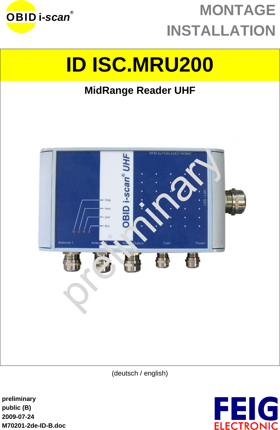
Feig Electronic MRU200 UHF Reader User Manual M70201 2de ID B
Feig Electronic GmbH UHF Reader M70201 2de ID B
UserManual.wiki
>
Feig Electronic
>
MRU200 User Manual
>
Users Manual
Contents
1.
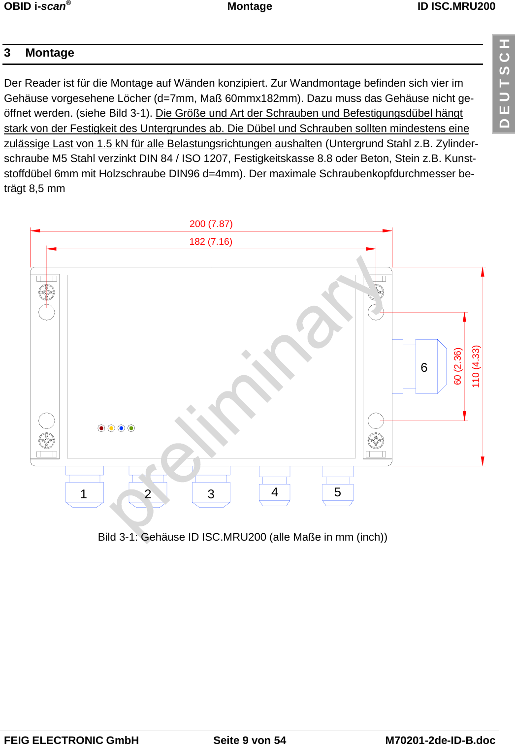
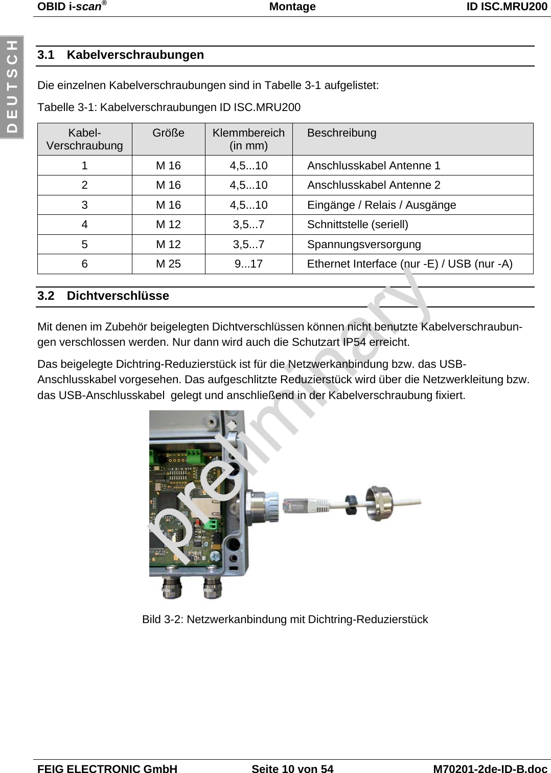
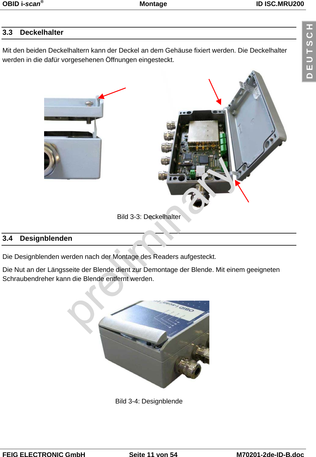
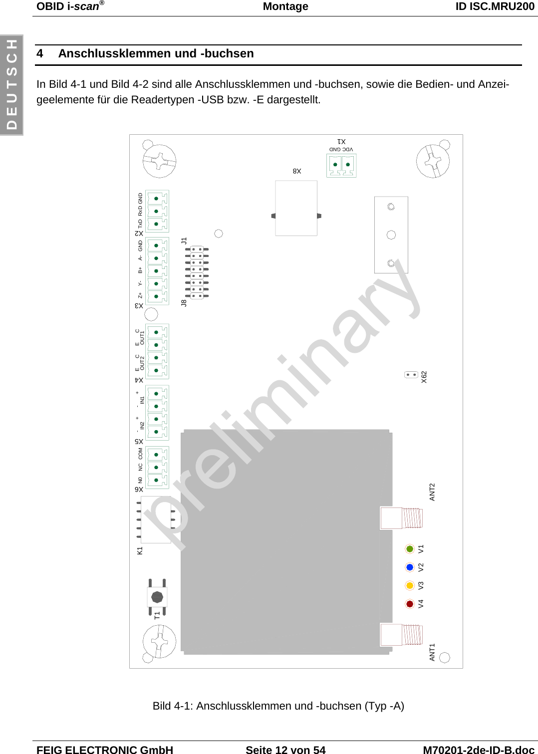
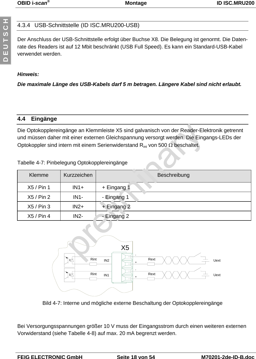
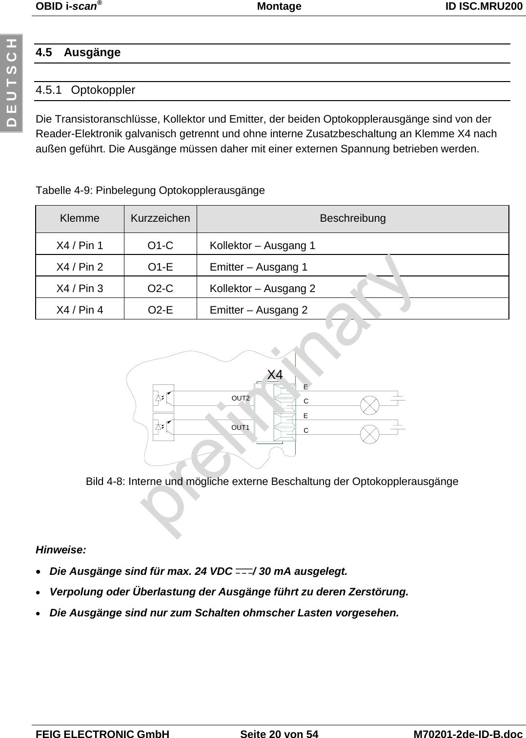
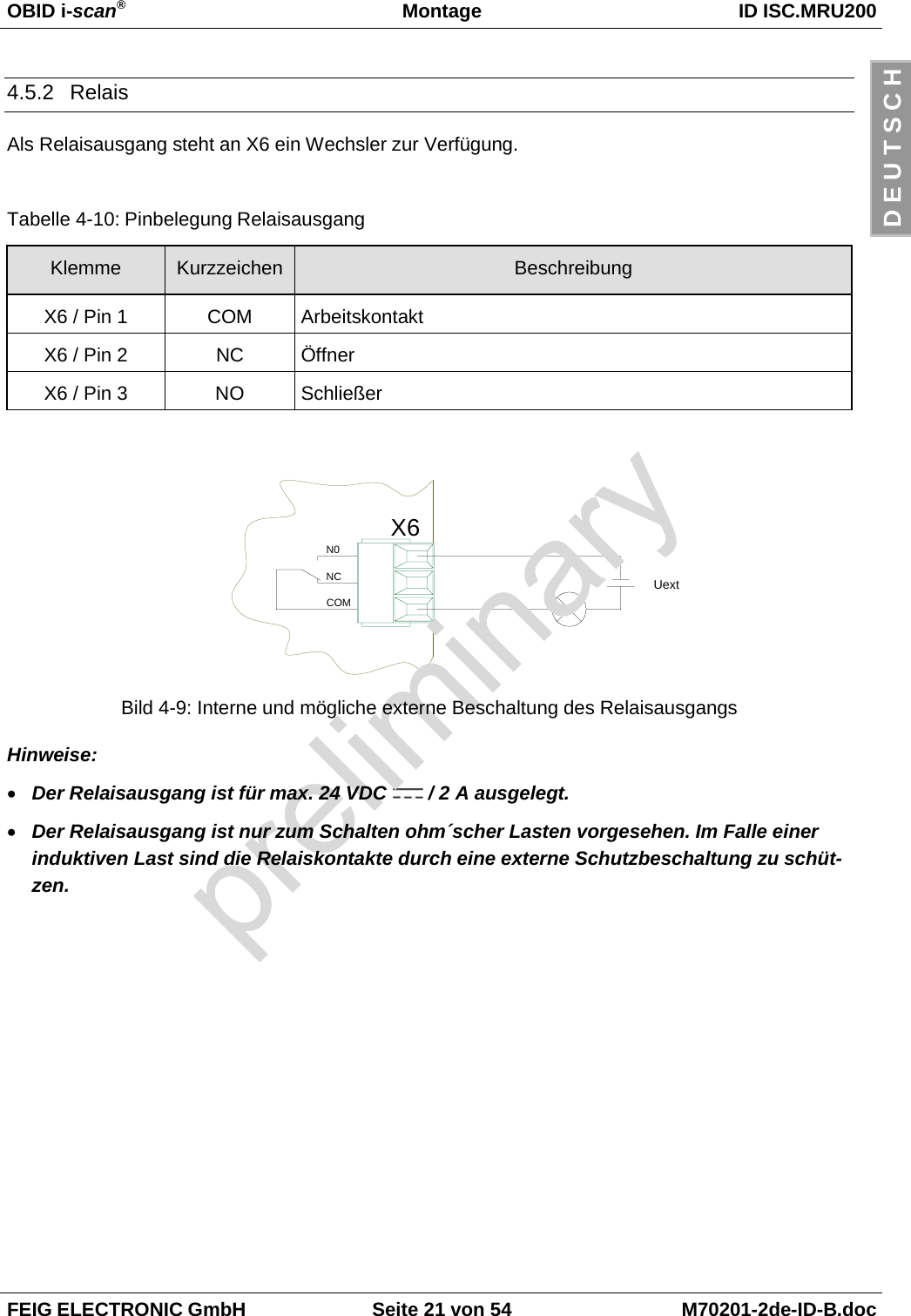
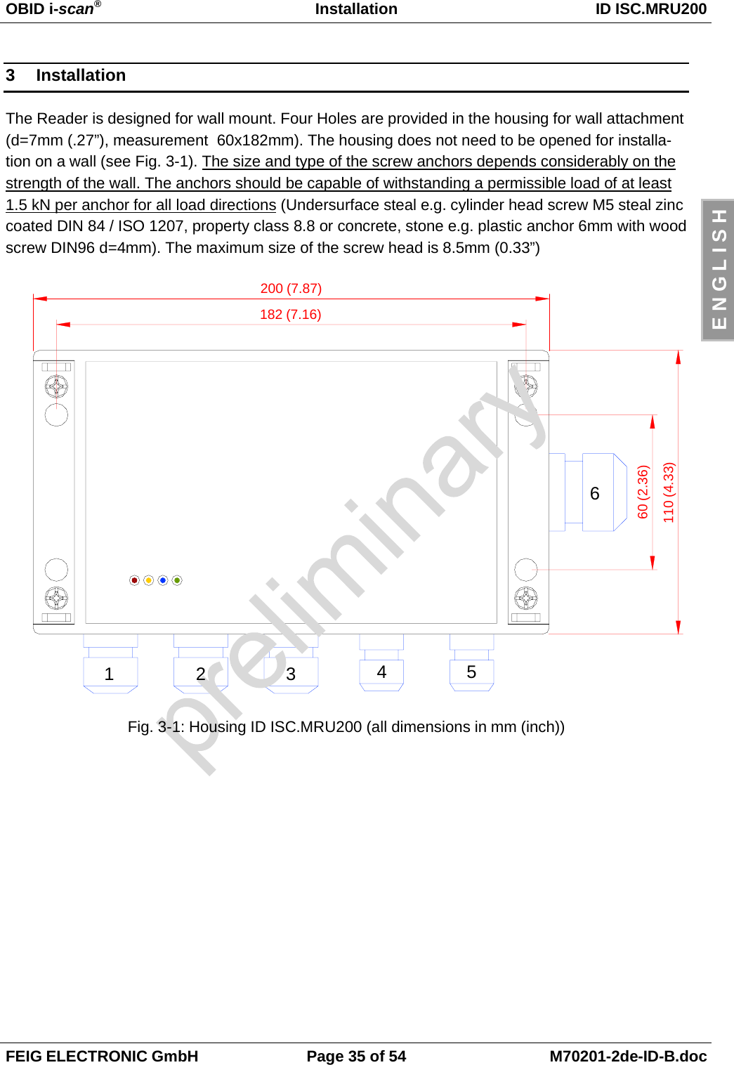
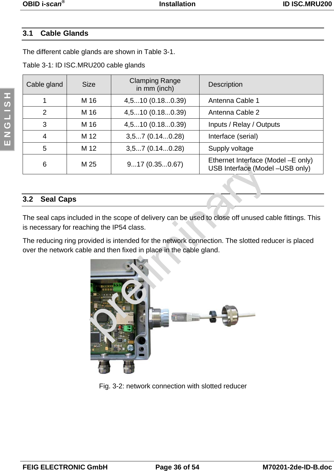
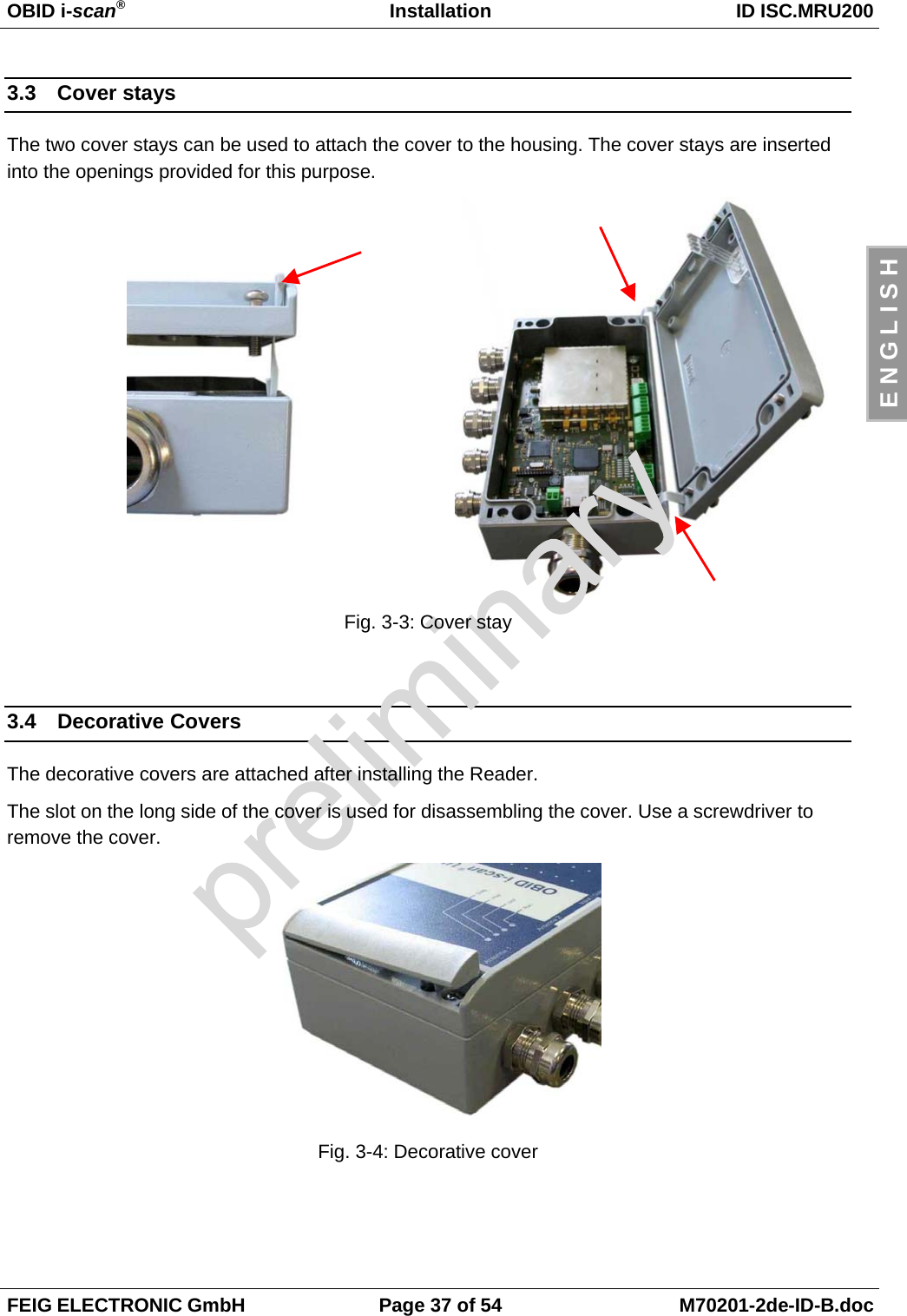
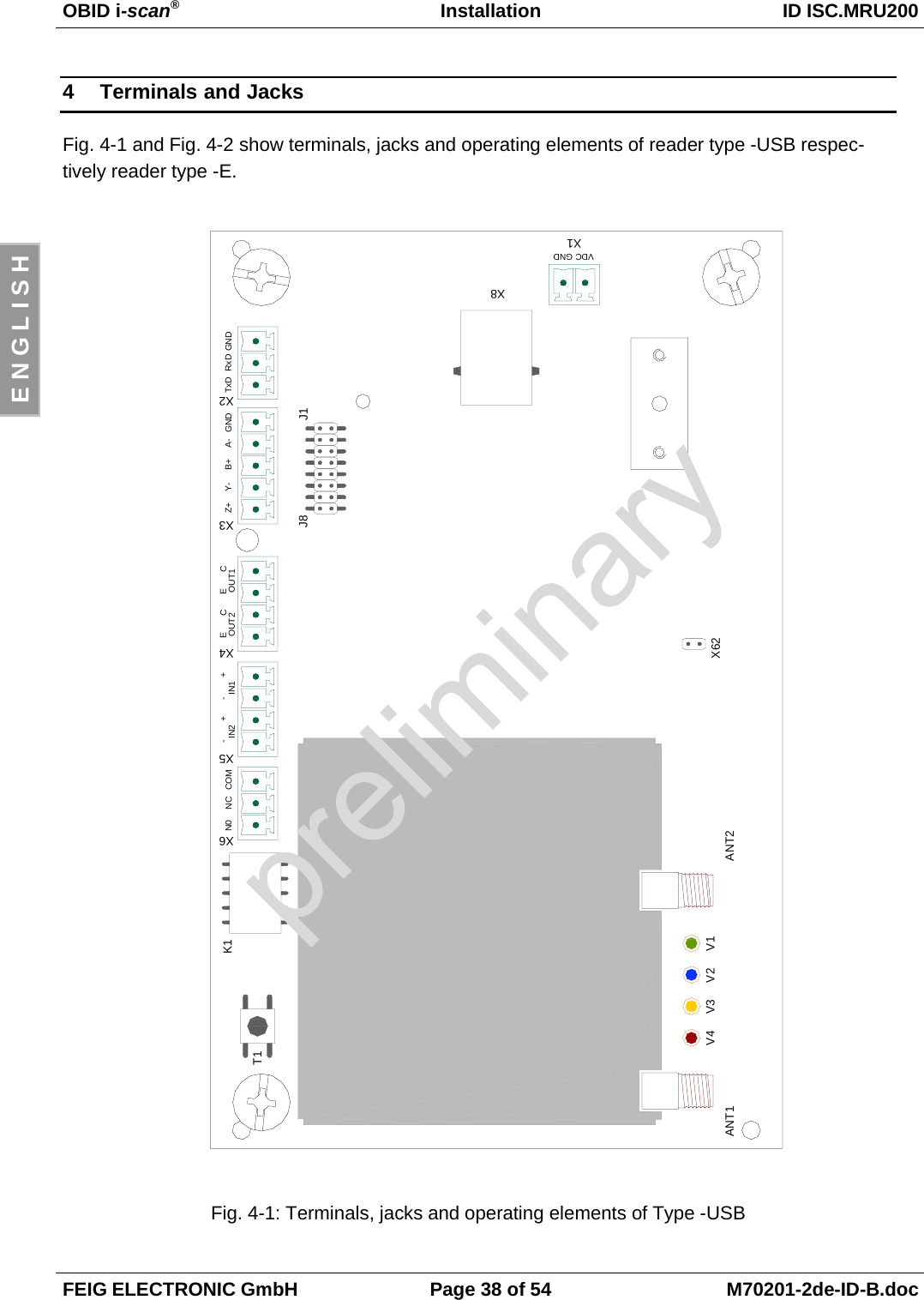
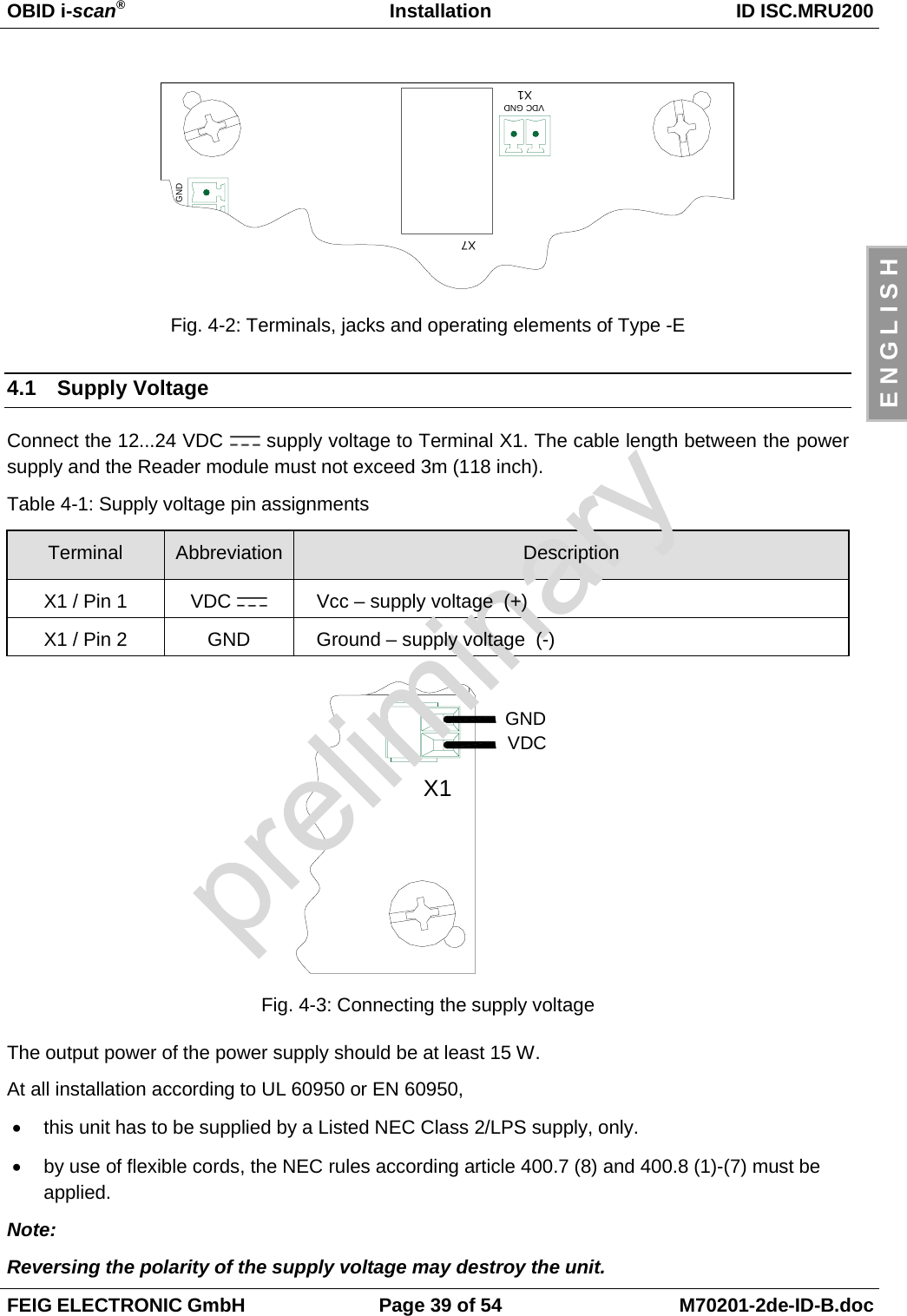
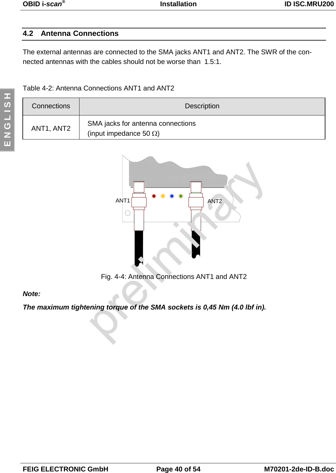
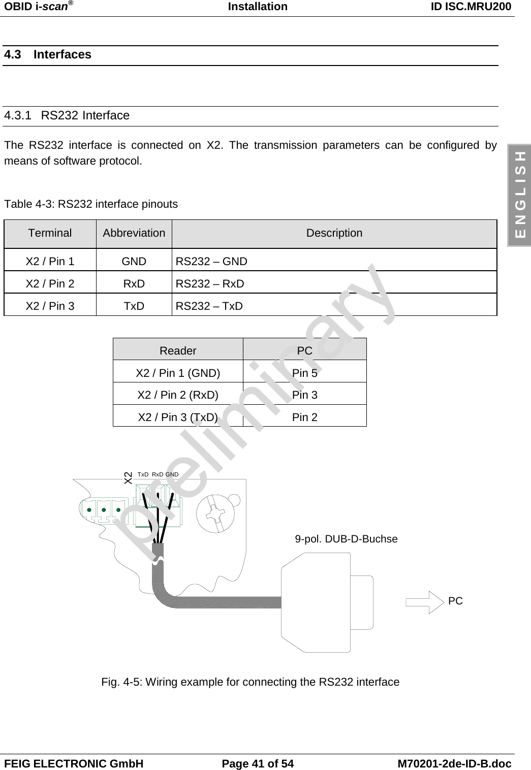
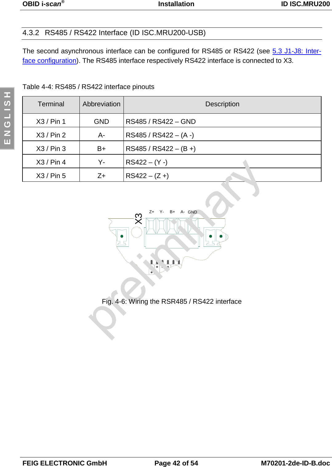
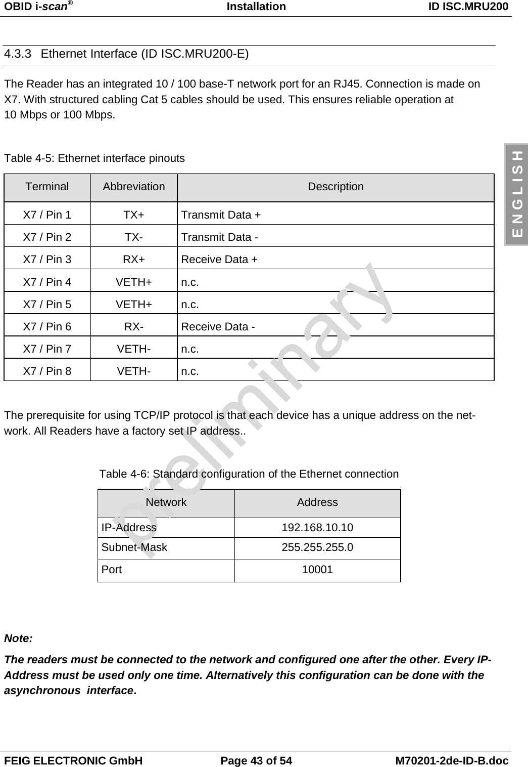
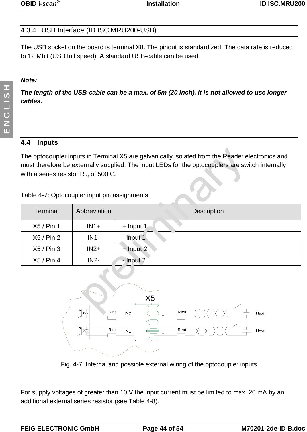
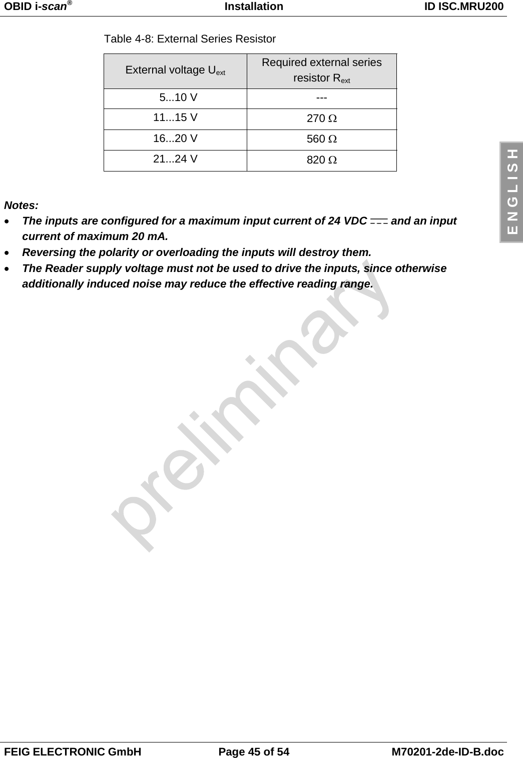
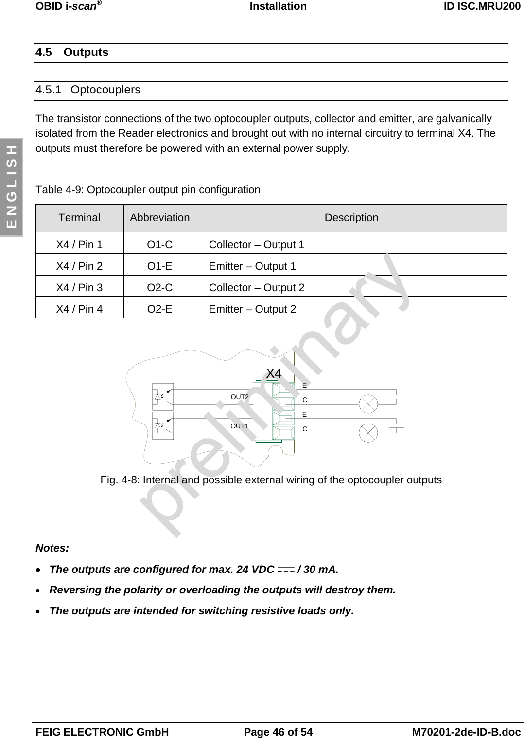
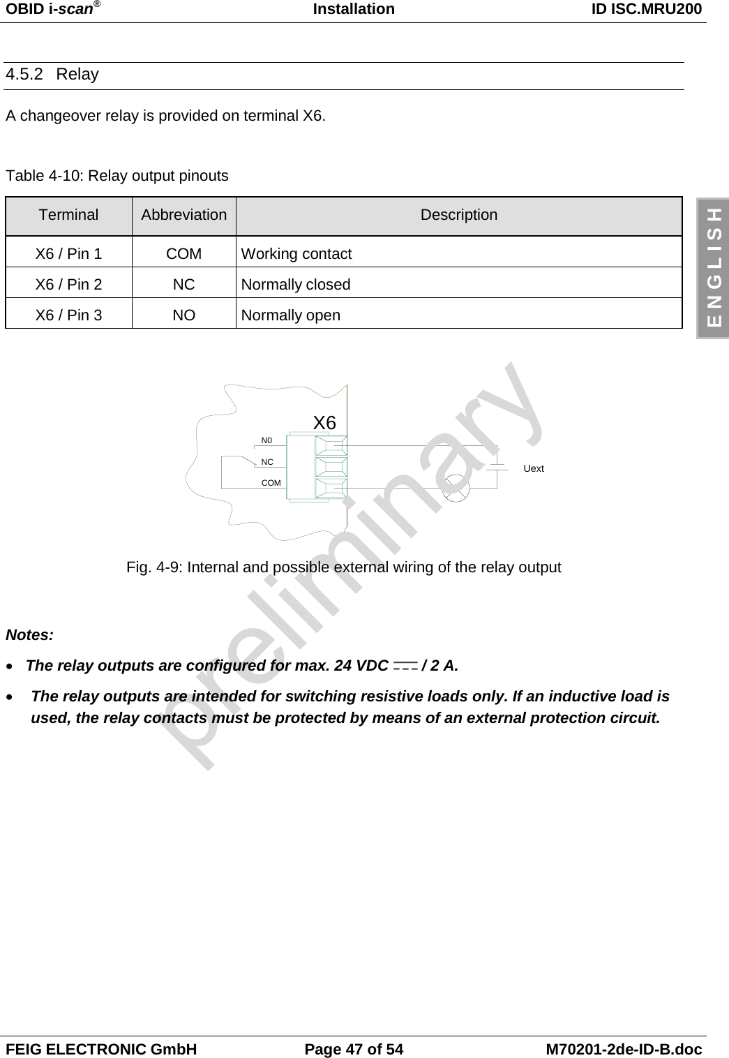
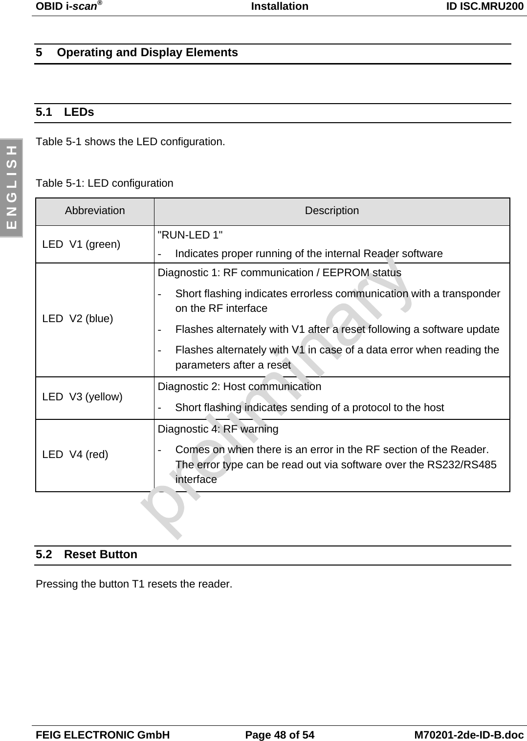
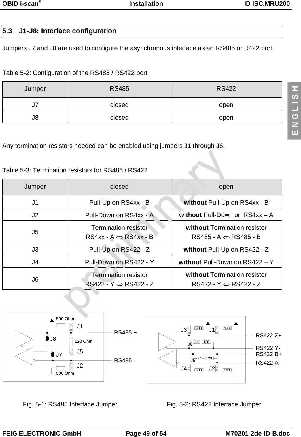
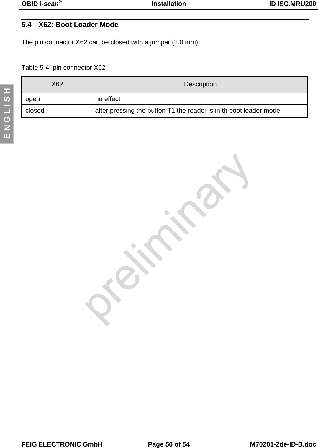
Installation Manual
2.
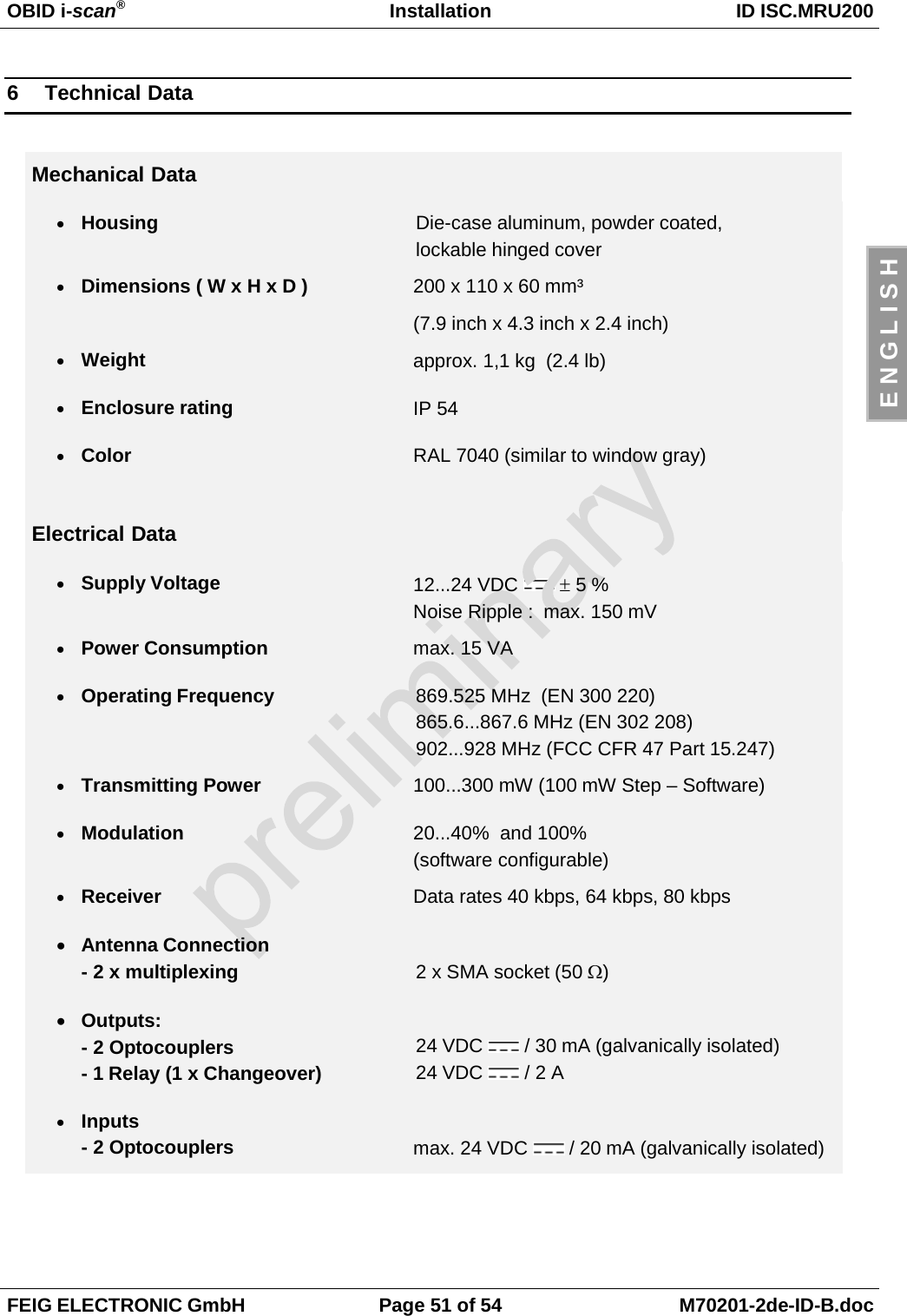
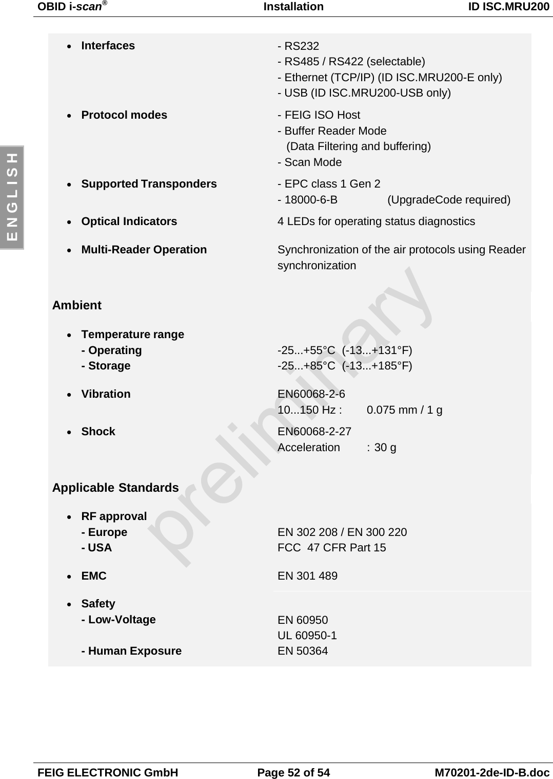
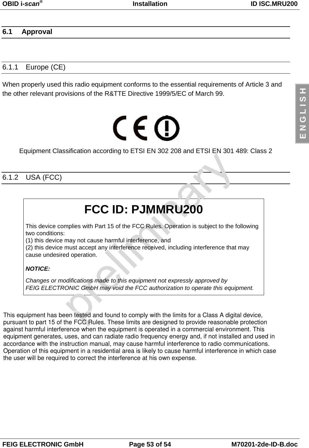
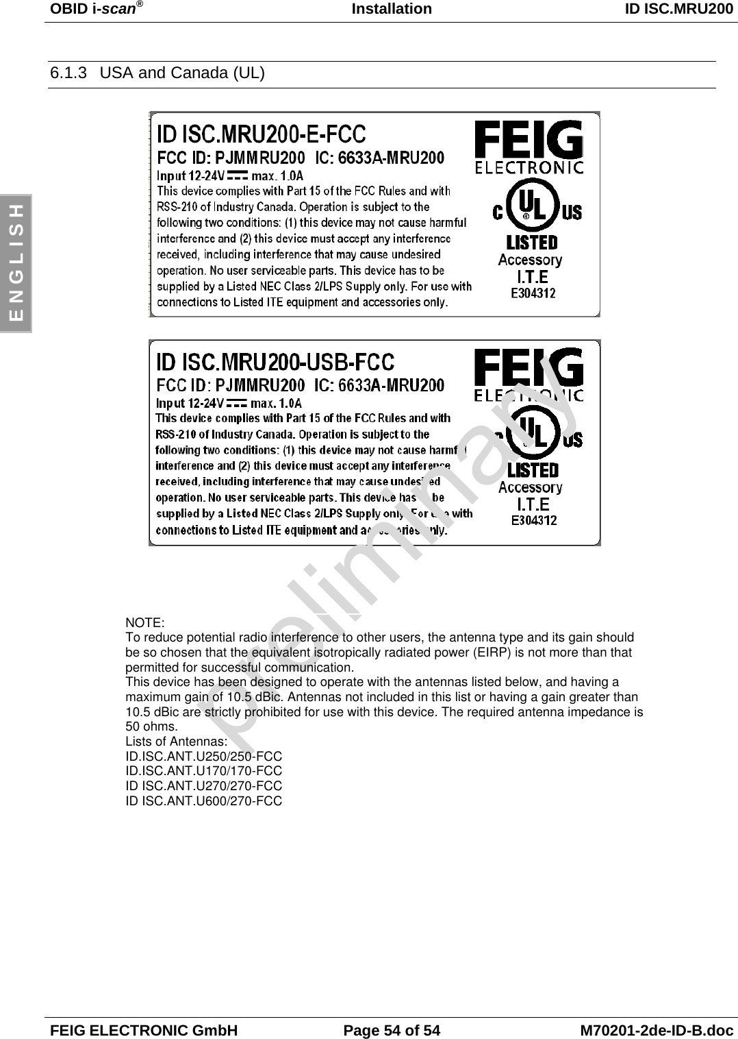
Users Manual
Users Manual
Navigation menu
Upload a User Manual
Namespaces
Wiki Guide
HTML
PDF
Info
Views
User Manual
Discussion / Help
Navigation