Feig Electronic MU02 UHF RFID MODULE User Manual
Feig Electronic GmbH UHF RFID MODULE
User Manual
MONTAGE
INSTALLATION
final
public (B)
2010-02-12
M91002-0de-ID-B.doc
OBI
D
i-scan
®
ID ISC.MU02.02
(deutsch / english)


OBID® i-scan Montage ID ISC.MU02.02
FEIG ELECTRONIC GmbH Page 3 of 36 M91002-0de-ID-B.doc
D E U T S C H
Hinweis
© Copyright 2009 by
FEIG ELECTRONIC GmbH
Lange Straße 4
D-35781 Weilburg
Tel.: +49 6471 3109-0
http://www.feig.de
Alle früheren Ausgaben verlieren mit dieser Ausgabe ihre Gültigkeit.
Die Angaben in diesem Dokument können ohne vorherige Ankündigung geändert werden.
Weitergabe sowie Vervielfältigung dieses Dokuments, Verwertung und Mitteilung ihres Inhalts sind nicht
gestattet, soweit nicht ausdrücklich zugestanden. Zuwiderhandlung verpflichtet zu Schadenersatz. Alle
Rechte für den Fall der Patenterteilung oder Gebrauchsmuster-Eintragung vorbehalten.
Die Zusammenstellung der Informationen in diesem Dokument erfolgt nach bestem Wissen und Gewissen.
FEIG ELECTRONIC GmbH übernimmt keine Gewährleistung für die Richtigkeit und Vollständigkeit der An-
gaben in diesem Dokument. Insbesondere kann FEIG ELECTRONIC GmbH nicht für Folgeschäden auf
Grund fehlerhafter oder unvollständiger Angaben haftbar gemacht werden. Da sich Fehler, trotz aller Bemü-
hungen nie vollständig vermeiden lassen, sind wir für Hinweise jederzeit dankbar.
Die in diesem Dokument gemachten Installationsempfehlungen gehen von günstigsten Rahmenbedingun-
gen aus. FEIG ELECTRONIC GmbH übernimmt weder Gewähr für die einwandfreie Funktion in system-
fremden Umgebungen, noch für die Funktion eines Gesamtsystems, welches die in diesem Dokument be-
schriebenen Geräte enthält.
FEIG ELECTRONIC weist ausdrücklich darauf hin, dass die in diesem Dokument beschriebenen Geräte
nicht für den Einsatz mit oder in medizinischen Geräten oder für Geräte für lebenserhaltende Maßnahmen
konzipiert sind, bei denen ein Fehler eine Gefahr für menschliches Leben oder für die gesundheitliche Un-
versehrtheit zur Folge haben kann. Der Applikationsdesigner ist dafür verantwortlich geeignete Maßnahmen
zu ergreifen um Gefahren, Schäden oder Verletzungen zu vermeiden.
FEIG ELECTRONIC GmbH übernimmt keine Gewährleistung dafür, dass die in diesem Dokument enthal-
tenden Informationen frei von fremden Schutzrechten sind. FEIG ELECTRONIC GmbH erteilt mit diesem
Dokument keine Lizenzen auf eigene oder fremde Patente oder andere Schutzrechte.
OBID® und OBID i-scan® ist ein eingetragenes Warenzeichen der FEIG ELECTRONIC GmbH.

OBID® i-scan Montage ID ISC.MU02.02
FEIG ELECTRONIC GmbH Page 4 of 36 M91002-0de-ID-B.doc
D E U T S C H
Inhalt
1. Sicherheits- und Warnhinweise - vor Inbetriebnahme unbedingt lesen 5
2. Leistungsmerkmale des Readermoduls ID ISC.MU02.02 6
2.1. Leistungsmerkmale.............................................................................................................6
2.2. Verfügbare Readertypen.....................................................................................................6
2.3. Optional erhältlich...............................................................................................................6
3. Montage und Anschluss 7
3.1. Abmessungen......................................................................................................................7
3.2. Anschluss RS232- und Daten-/Takt-Schnittstelle X2.......................................................8
3.2.1. Spannungsversorgung...................................................................................................9
3.2.2. RS232-Schnittstelle .....................................................................................................10
3.2.3. Daten-/Taktschnittstelle ...............................................................................................11
3.2.4. Abschaltung.................................................................................................................12
3.3. Anschluss USB-Schnittstelle X1......................................................................................12
3.4. Antennenanschluss ..........................................................................................................13
3.5. Anzeigeelemente...............................................................................................................14
3.6. Montagehinweise ..............................................................................................................15
3.6.1. Metallische Umgebung ................................................................................................15
3.6.2. EMV-Beeinflussung über Zuleitungen .........................................................................16
4. Funkzulassungen 16
4.1. Europa (CE)........................................................................................................................16
4.2. USA (FCC)..........................................................................................................................17
5. Technische Daten 18

OBID® i-scan Montage ID ISC.MU02.02
FEIG ELECTRONIC GmbH Page 5 of 36 M91002-0de-ID-B.doc
D E U T S C H
1. Sicherheits- und Warnhinweise - vor Inbetriebnahme unbedingt lesen
• Das Gerät darf nur für den vom Hersteller vorgesehenen Zweck verwendet werden.
• Beim Aufstellen des Gerätes im Geltungsbereich der FCC 47 CFR Part 15 ist ein Mindestab-
stand von 23cm (8inch) zwischen Antenne und menschlichem Körper zu gewährleisten.
• Die Bedienungsanleitung ist zugriffsfähig aufzubewahren und jedem Benutzer auszuhändigen.
• Unzulässige Veränderungen und die Verwendung von Ersatzteilen und Zusatzeinrichtungen,
die nicht vom Hersteller des Gerätes verkauft oder empfohlen werden, können Brände, elektri-
sche Schläge und Verletzungen verursachen. Solche Maßnahmen führen daher zu einem
Ausschluss der Haftung und der Hersteller übernimmt keine Gewährleistung.
• Für das Gerät gelten die Gewährleistungsbestimmungen des Herstellers in der zum Zeitpunkt
des Kaufs gültigen Fassung. Für eine ungeeignete, falsche manuelle oder automatische Ein-
stellung von Parametern für ein Gerät bzw. ungeeignete Verwendung eines Gerätes wird keine
Haftung übernommen.
• Reparaturen dürfen nur vom Hersteller durchgeführt werden.
• Anschluss-, Inbetriebnahme-, Wartungs-, und sonstige Arbeiten am Gerät dürfen nur von Elekt-
rofachkräften mit einschlägiger Ausbildung erfolgen.
• Alle Arbeiten am Gerät und dessen Aufstellung müssen in Übereinstimmung mit den nationa-
len elektrischen Bestimmungen und den örtlichen Vorschriften durchgeführt werden.
• Beim Arbeiten an dem Gerät müssen die jeweils gültigen Sicherheitsvorschriften beachtet wer-
den.
• Besonderer Hinweis für Träger von Herzschrittmachern:
Obwohl dieses Gerät die zulässigen Grenzwerte für elektromagnetische Felder nicht über-
schreitet, sollten Sie einen Mindestabstand von 25 cm zwischen dem Gerät und Ihrem Herz-
schrittmacher einhalten.

OBID® i-scan Montage ID ISC.MU02.02
FEIG ELECTRONIC GmbH Page 6 of 36 M91002-0de-ID-B.doc
D E U T S C H
2. Leistungsmerkmale des Readermoduls ID ISC.MU02.02
2.1. Leistungsmerkmale
Das Readermodul ID ISC.MU02.02 ist für das Lesen und Schreiben von passiven Transpondern,
sogenannten "Smart Labels", mit einer Betriebsfrequenz von 860 - 960 MHz entwickelt worden. Es
eignet sich für alle Anwendungen, bei denen geringe bis mittlere Lesereichweiten bei kleinen Ab-
messungen des Readers benötigt werden.
Das Modul besitzt 2 integrierte Antennenausgänge, an die jeweils eine externe 50 Ω-Antenne an-
geschlossen werden kann.
2.2. Verfügbare Readertypen
Folgende Readertypen sind z.Z. verfügbar:
Readertyp Beschreibung
ID ISC.MU02.02-AD Readermodul mit RS232- und Daten-/Takt-Schnittstelle, externe Ver-
sorgungsspannung von 5 V DC
ID ISC.MU02.02-CU Readermodul mit RS232-LVTTL- und USB-Schnittstelle, externe Ver-
sorgungsspannung von 5 V DC oder über USB
2.3. Optional erhältlich
Folgende Komponenten sind optional erhältlich. Diese Komponenten werden zum Beispiel benö-
tigt, um den Reader ID ISC.MU02.02 an einem COM-Port zu betreiben.
Zubehör: Bestellnummer:
ID CAB.A-A Adapterkabel für RS232 und Daten/Takt 2259.000.00.00
ID CAB.RS-A Kabel für RS232 und Spannungsversorgung 1690.000.00.00
RS232-TTL Konverter 1962.000.00.00
ID Net.5V Netzteil 1689.000.00.01
ID CAB.USB-B Kabel für USB 3541.000.00.00
ID ISC.ANT.C05-A UHF-Antennenkabel U.FL-U.FL 500 mm 3540.000.00.00
ID ISC.ANT.U75/50-EU UHF-Antennenmodul 865 – 868 MHz 3544.000.00.00
ID ISC.ANT.U75/50-FCC UHF-Antennenmodul 902 – 928 MHz 3543.000.00.00
OBID® i-scan Montage ID ISC.MU02.02
FEIG ELECTRONIC GmbH Page 7 of 36 M91002-0de-ID-B.doc
D E U T S C H
3. Montage und Anschluss
3.1. Abmessungen
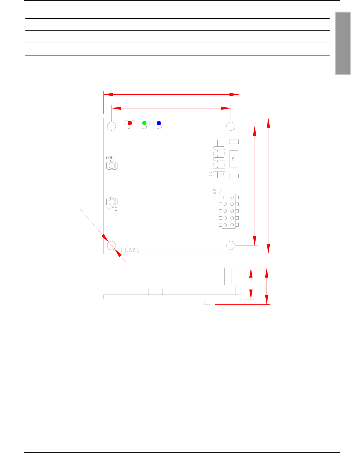
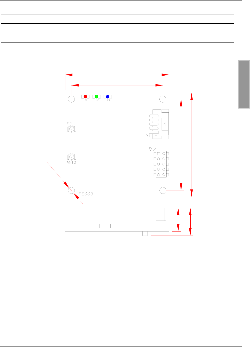
Bild 1 zeigt die Maßzeichnung des Readermoduls ID ISC.MU02.02 in mm.
Bild 1: Maßzeichnung des Readermoduls ID ISC.MU02.02 in mm
13,4
50
50
44
44
Ø3,2
11,4
OBID® i-scan Montage ID ISC.MU02.02
FEIG ELECTRONIC GmbH Page 8 of 36 M91002-0de-ID-B.doc
D E U T S C H
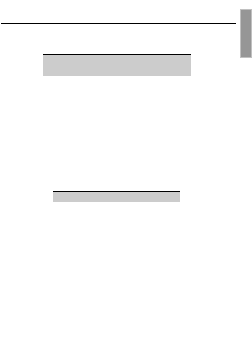
3.2. Anschluss RS232- und Daten-/Takt-Schnittstelle X2
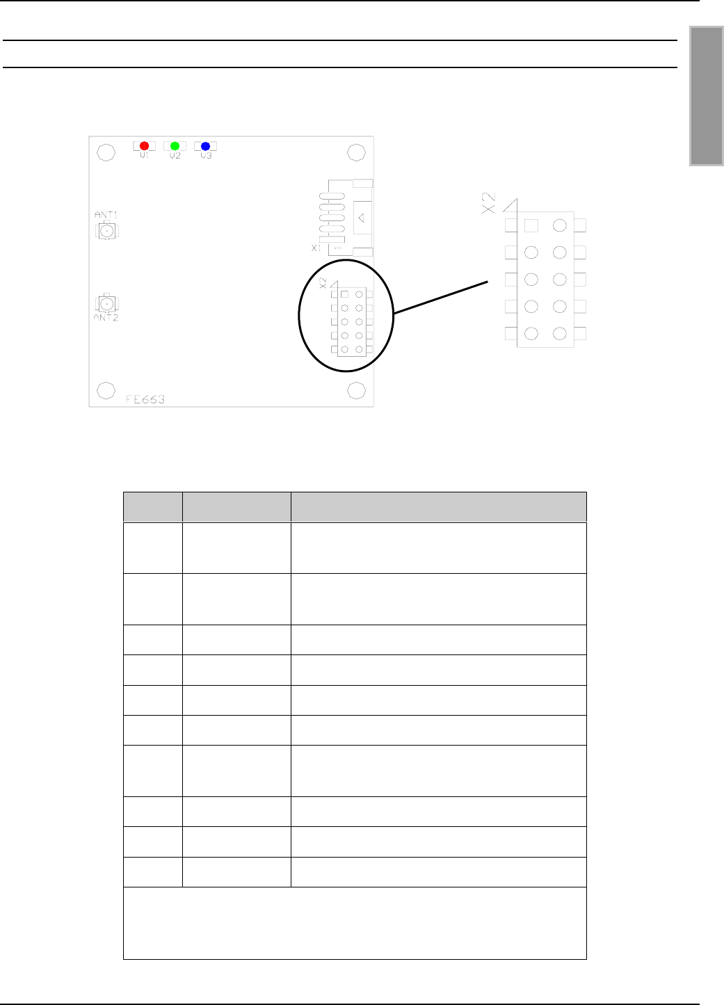
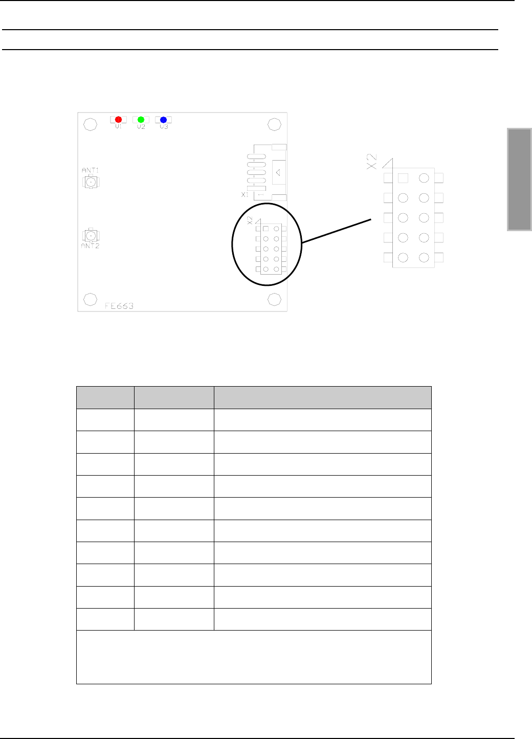
Bild 2 und Tabelle 1 zeigen die Belegung der Anschlussstiftleiste X2. Die Stiftleiste ist für
Flachbandkabelanschluss mittels IDC-Federleiste mit Rastermaß 2,54 mm ausgelegt.
Bild 2: Belegung der Anschlussstiftleiste X2
Pin Kurzzeichen Beschreibung
1DAT Datenleitung der
Daten-/Taktschnittstelle
2CLK Taktleitung der
Daten-/Taktschnittstelle
3TxD RS232 – Transmit Data
4GND ** Masse
5RxD RS232 – Receive Data
6SHDN Abschaltung
7CLS CLS-Leitung der
Daten-/Taktschnittstelle
8VCC * + 5 V DC
9GND ** Masse
10 -- Keine Funktion (NUR offen betreiben!)
* Nur geregelte DC-Spannungen verwenden !
** Die GND-Pins 4 und 9 sind auf dem Readermodul direkt
miteinander verbunden
Tabelle 1: Belegung der Anschlussstiftleiste X2
12
34
56
78
910
OBID® i-scan Montage ID ISC.MU02.02
FEIG ELECTRONIC GmbH Page 9 of 36 M91002-0de-ID-B.doc
D E U T S C H
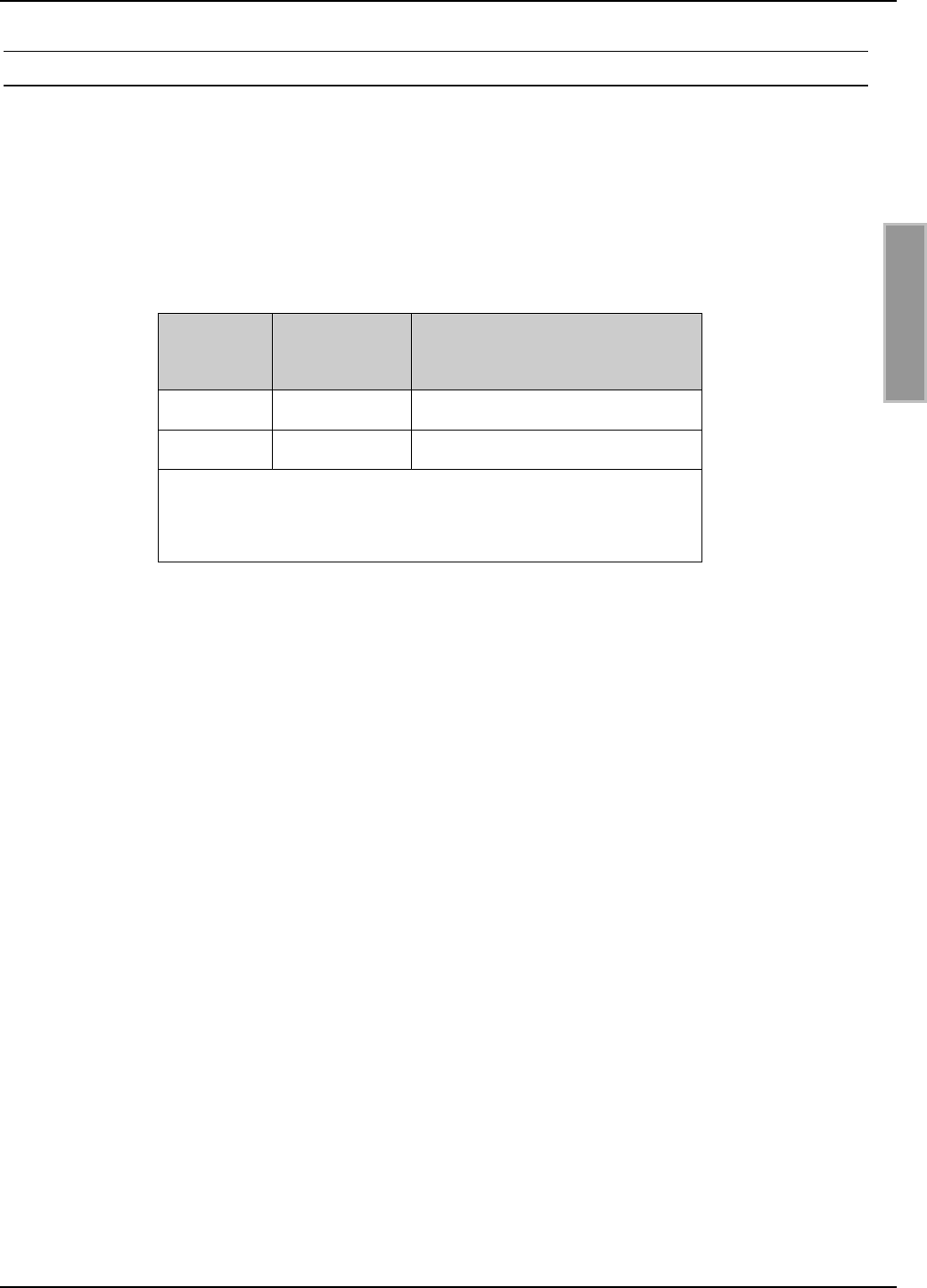
3.2.1. Spannungsversorgung
Für die Spannungsversorgung des ID ISC.MU02.02 dürfen nur geregelte DC-Spannungen ver-
wendet werden.
Im Falle von getakteten Netzteilen zur Versorgung des Moduls ist auf eine ausreichende Filterung
der Versorgungsspannung zu achten.
Störungen der Versorgungsspannung können sich in einer Reduzierung der Lese- und Schreib-
reichweite des Modules auswirken.
Die Länge des Zuleitungskabels der Spannungsversorgung sollte möglichst kurz sein. Sie darf 3 m
nicht überschreiten.
X2
Pin-Nr. Kurzzeichen Beschreibung
8VCC * + 5 V DC ± 5%
4, 9 GND ** Masse
* Nur geregelte DC-Spannungen verwenden !
** Die GND-Pins 4 und 9 sind auf dem Readermodul
direkt miteinander verbunden
Tabelle 2: Pinbelegung der Spannungsversorgung an X2
HINWEIS:
• Eine Verpolung der Versorgungsspannung kann zur Zerstörung des Gerätes führen.
• Versorgungsspannungen außerhalb der Spezifikation können zur Zerstörung des Gerä-
tes führen.
OBID® i-scan Montage ID ISC.MU02.02
FEIG ELECTRONIC GmbH Page 10 of 36 M91002-0de-ID-B.doc
D E U T S C H
3.2.2. RS232-Schnittstelle
Die Länge des Zuleitungskabels der RS232-Schnittstelle sollte möglichst kurz sein. Sie darf 3 m
nicht überschreiten.
X2
Pin-Nr. Kurzzeichen Beschreibung
3TxD * RS232 - Transmit Data
4, 9 GND ** Masse
5RxD * RS232 - Receive Data
* Bezeichnungen der Signale aus Sichtweise des
Readermoduls.
** Die GND-Pins 4 und 9 sind auf dem Readermodul
direkt miteinander verbunden
Tabelle 3: Pinbelegung der RS232-Schnittstelle an X2
Die Übertragungsparameter der Schnittstelle können per Softwareprotokoll konfiguriert werden.
Tabelle 4 zeigt die Standardparameter der RS232-Schnittstelle.
Parameter Standardeinstellung
Baudrate 38400
Anzahl der Datenbits 8
Parität Even
Anzahl der Stoppbits 1
Tabelle 4: Standardparameter der RS232-Schnittstelle.
Hinweis:
• Wird an einem angeschlossenen PC/Notebook ein USB / RS232-Konverter benutzt, so
sollte der COM-Port Parameter „Char Timeout Multiplier“ von „1“ auf ca. „10“ erhöht
werden.
• Wird ein RS232 / TTL-Konverter ohne externe Spannungsversorgung benutzt, kann es
notwendig sein das die COM -Port Parameter “RTS” und “DTR” manuell eingeschaltet
werden müssen.
OBID® i-scan Montage ID ISC.MU02.02
FEIG ELECTRONIC GmbH Page 11 of 36 M91002-0de-ID-B.doc
D E U T S C H
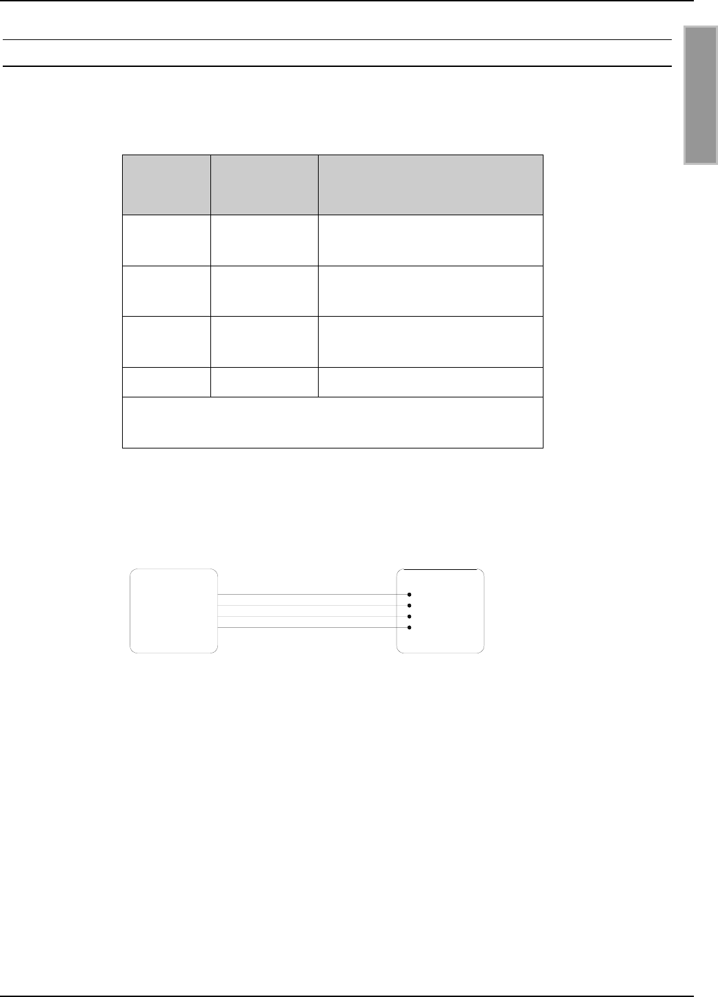
3.2.3. Daten-/Taktschnittstelle
Die Länge des Zuleitungskabels der Daten-/Taktschnittstelle sollte möglichst kurz sein. Sie darf
3 m nicht überschreiten.
X2
Pin-Nr. Kurzzeichen Beschreibung
1DAT Datenleitung der
Daten-/Taktschnittstelle
2CLK Taktleitung der
Daten-/Taktschnittstelle
7CLS CLS-Leitung der
Daten-/Taktschnittstelle
4, 9 GND * Masse
* Die GND-Pins 4 und 9 sind auf dem Readermodul
direkt miteinander verbunden
Tabelle 5: Pinbelegung der Daten-/Takt-Schnittstelle an X2
Bild 3: Anschluss der Daten-/Taktschnittstelle
Host
Data
Clock
CLS
GND
DAT
GND
CLK
CLS ID ISC.MU02
OBID® i-scan Montage ID ISC.MU02.02
FEIG ELECTRONIC GmbH Page 12 of 36 M91002-0de-ID-B.doc
D E U T S C H
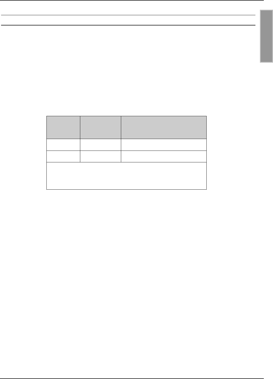
3.2.4. Abschaltung
Mit Hilfe des SHDN-Kontakts (Pin-Nr. 6 an Stiftleiste X2) kann der ID ISC.MU02.02 abgeschaltet
werden. Dafür muss der Kontakt auf Masse gelegt werden.
X2
Pin-Nr. 6 Betriebszustand
nicht verbunden an
Masse (GND) aus
Tabelle 6: Zustandstabelle für SHDN-Kontakt
HINWEIS:
• Versorgungsspannungen außerhalb der Spezifikation können zur Zerstörung des Gerä-
tes führen.
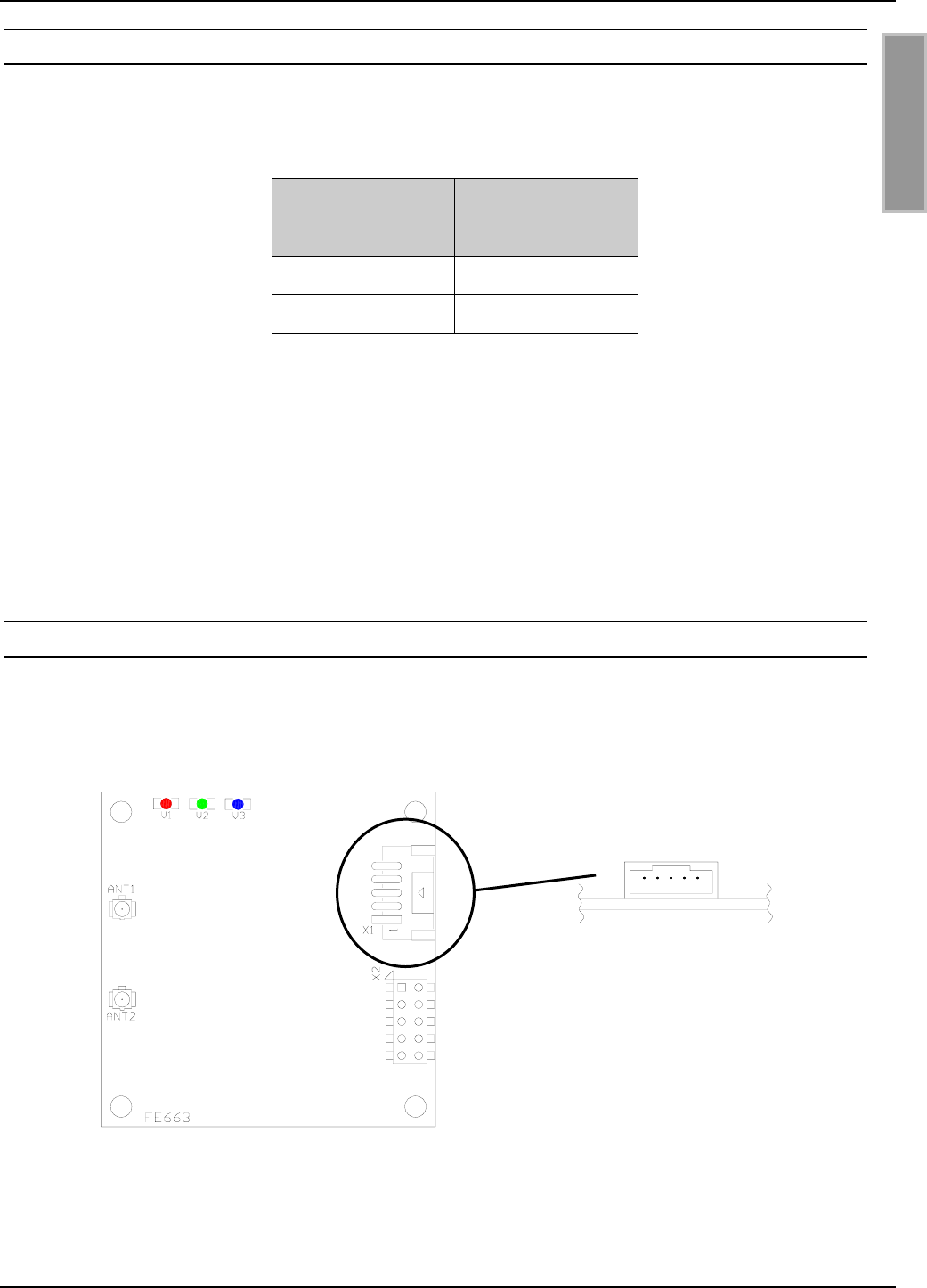
3.3. Anschluss USB-Schnittstelle X1
Bild 4 und Tabelle 7 zeigen die Belegung des Anschlusssteckers X1 vom Typ “JST PH” Raster-
maß 2 mm (liegend).
Bild 4: Belegung der Anschlussstiftleiste X1
15
OBID® i-scan Montage ID ISC.MU02.02
FEIG ELECTRONIC GmbH Page 13 of 36 M91002-0de-ID-B.doc
D E U T S C H
Pin Kurzzeichen Beschreibung
1SHIELD Schirmung
2GND Masse
3D + USB-D PLUS
4D – USB-D MINUS
5VCC 5 V Spannungsversorgung
Tabelle 7: Belegung der Anschlussstiftleiste X1
Die Stromversorgung des Gerätes erfolgt über die USB-Schnittstelle (Bus-Powered).
Die USB-Schnittstelle muss einen Strom von 500 mA liefern können (High Powered Interface).
Die Datenrate des Readers ist auf 12 Mbit beschränkt (USB high speed).
Wird der Reader zum ersten mal über USB in Betrieb genommen, muss er im Betriebssystem des
Computers angemeldet werden. Details entnehmen Sie bitte der Anleitung M70700-xde-ID-B: „In-
stallation OBID® USB-Treiber“.
HINWEIS:
• Wenn der ID ISC.MU02.02 über die USB-Schnittstelle mit Spannung versorgt wird, darf
keine weitere Spannungsquelle an die Stiftleiste X2 angeschlossen werden.
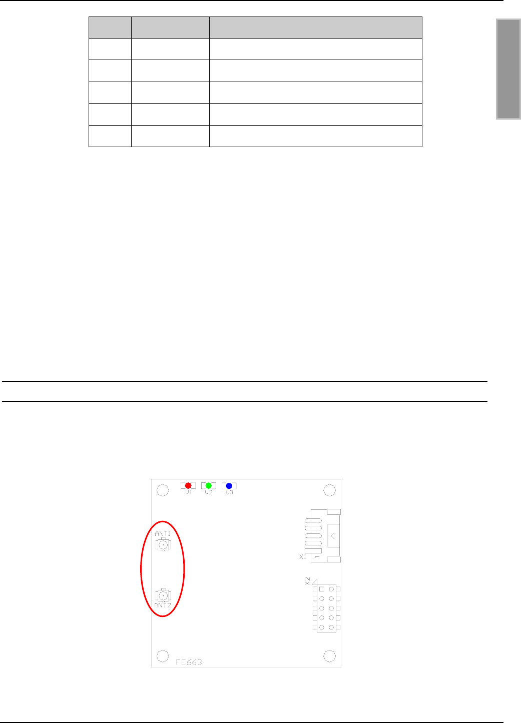
3.4. Antennenanschluss
Über die Antennenbuchsen ANT1 und ANT2 können bis zu 2 Antennen an den ID ISC.MU02.02
angeschlossen werden. Bild 5 zeigt die Position der Antennenbuchsen vom Typ “Hirose U.FL”. Die
Eingangsimpedanz der Buchsen beträgt 50 Ω. Die Antennen können per Software umgeschaltet
werden.
Bild 5: Position der Antennenbuchsen ANT1 und ANT2
OBID® i-scan Montage ID ISC.MU02.02
FEIG ELECTRONIC GmbH Page 14 of 36 M91002-0de-ID-B.doc
D E U T S C H
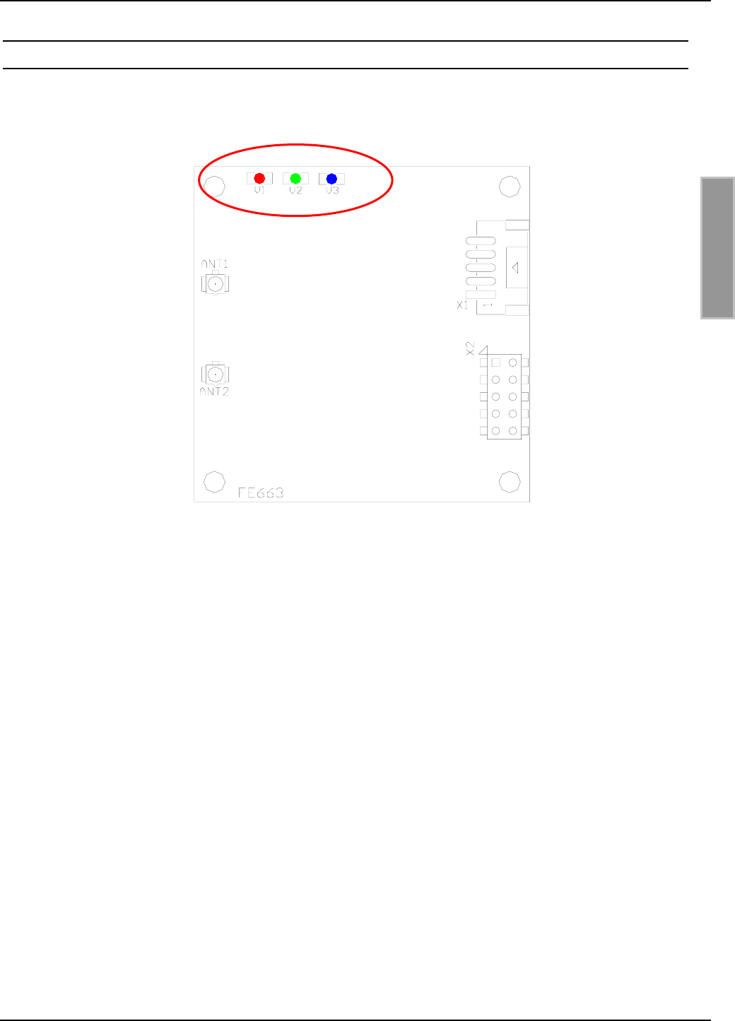
3.5. Anzeigeelemente
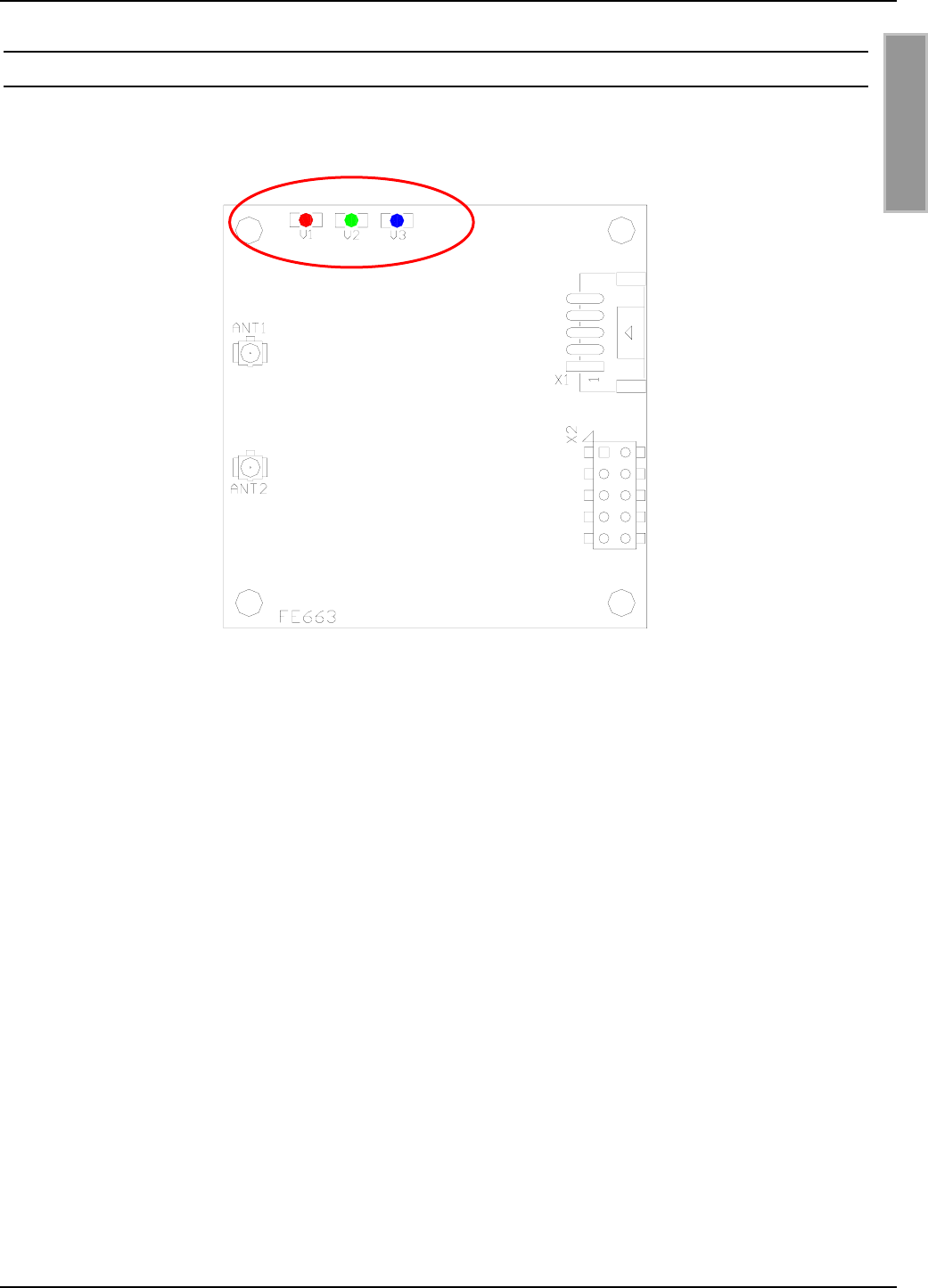
Das Readermodul ID ISC.MU02.02 besitzt eine rote LED (V1), eine grüne LED (V2) und eine
blaue LED (V3) als Anzeigeelemente (siehe Bild 6).
Bild 6: Position der LED´s
Die Funktionen der beiden LED´s V2 und V3 können per Softwareprotokoll konfiguriert werden.
Ergänzend dazu besteht auch die Möglichkeit alle 3 LED´s direkt durch ein weiteres
Softwareprotokoll anzusteuern.
Tabelle 8 zeigt die Standardeinstellung von V1, V2 und V3.

OBID® i-scan Montage ID ISC.MU02.02
FEIG ELECTRONIC GmbH Page 15 of 36 M91002-0de-ID-B.doc
D E U T S C H
LED Farbe Standardeinstellung
V1 Rot
• Blinkt nach einem Reset fünf mal.
• Leuchtet nicht im Normalbetrieb
• Blinkt im Fehlerfall im Wechsel mit V2
V2 Grün
• Blinkt nach einem Reset fünf mal.
• Leuchtet kontinuierich, bei keiner
Transponderkommunikation
• Leuchtet nicht bei
Transponderkommunikation
• Blinkt im Fehlerfall im Wechsel mit V1
V3 Blau
• Blinkt nach einem Reset zehn mal.
• Leuchtet nach einer erfolgreichen
Kommunikation mit einem Transponder für
1 Sekunde.
Tabelle 8: Standardeinstellung der LED´s
3.6. Montagehinweise
Folgende mögliche Beeinflussungen durch die Umgebung sollten beim Einbau eines ID
ISC.MU02.02 in ein anderes Gerät beachtet werden :
• Beeinflussung durch eine metallische Umgebung
⇒ Verstimmung der angeschlossenen Antennen
⇒ Beeinträchtigung der Ausbreitung des elektromagnetischen Feldes der Antennen
• EMV-Beeinflussung über Zuleitungen
⇒ Beeinträchtigung der Kommunikation zwischen Reader und Label
3.6.1. Metallische Umgebung
Beim Einbau eines ID ISC.MU02.02 in ein anderes Gerät ist darauf zu achten, dass sich möglichst
keine Metallflächen bzw. Metallteile in der direkten Umgebung der angeschlossenen Antennen
befinden. Diese können die Antennen verstimmen und die Ausbreitung des elektromagnetischen
Feldes durch Reflexionen beeinträchtigen. Dies führt zu Leselöchern und Überreichweiten.
Der Abstand zwischen Antenne und Metallfläche sollte mindestens 5 cm betragen. Dabei
sollte bedacht werden, dass sich auch andere Leiterplatten, je nach Kupferauflage, wie Me-
tallflächen verhalten.
Ist eine metallische Umgebung nicht zu vermeiden, so sollten die Abstände im Interesse der sta-
bilen Funktion jedoch so groß wie nur irgend möglich gewählt werden.

OBID® i-scan Montage ID ISC.MU02.02
FEIG ELECTRONIC GmbH Page 16 of 36 M91002-0de-ID-B.doc
D E U T S C H
Auch der Bereich zwischen Antenne und Transponder, sowie der Bereich auf der anderen Seite
des Transponders sollte frei von Metallteilen sein.
3.6.2. EMV-Beeinflussung über Zuleitungen
Trotz der internen EMV-Filter des Readers kann es durch starke Störungen auf der Spannungs-
versorgung zu Beeinträchtigungen der Kommunikation zwischen Reader und Transponder kom-
men.
Beim Einbau eines ID ISC.MU02.02 in ein anderes Gerät sollte daher auf eine möglichst saubere,
störfreie Spannungsversorgung geachtet werden.
4. Funkzulassungen
4.1. Europa (CE)
Die Funkanlage entspricht, bei bestimmungsgemäßer Verwendung den grundlegenden Anforde-
rungen des Artikels 3 und den übrigen einschlägigen Bestimmungen der R&TTE Richtlinie
1999/5/E6 vom März 99.
Equipment Classification gemäß ETSI EN 301 489: Class 2

OBID® i-scan Montage ID ISC.MU02.02
FEIG ELECTRONIC GmbH Page 17 of 36 M91002-0de-ID-B.doc
D E U T S C H
4.2. USA (FCC)
FCC ID: PJMMU02
This device complies with Part 15 of the FCC Rules. Operation is subject to the following
two conditions:
(1) this device may not cause harmful interference, and
(2) this device must accept any interference received, including interference that may
cause undesired operation.
NOTICE:
Changes or modifications made to this equipment not expressly approved by
FEIG ELECTRONIC GmbH may void the FCC authorization to operate this equipment.
This equipment has been tested and found to comply with the limits for a Class B digital
device, pursuant to Part 15 of the FCC Rules. These limits are designed to provide rea-
sonable protection against harmful interference in a residential installation. This equip-
ment generates, uses and can radiate radio frequency energy and, if not installed and
used in accordance with the instructions, may cause harmful interference to radio com-
munications. However, there is no guarantee that interference will not occur in a particular
installation. If this equipment does cause harmful interference to radio or television recep-
tion, which can be determined by turning the equipment off and on, the user is encour-
aged to try to correct the interference by one or more of the following measures:
-- Reorient or relocate the receiving antenna.
-- Increase the separation between the equipment and receiver.
-- Connect the equipment into an outlet on a circuit different from that to
which the receiver is connected.
-- Consult the dealer or an experienced radio/TV technician for help.
This device is labeled with an FCC ID number.
If this label is not visible when installed in an end device, the outside of the device MUST
also display a label referring to the enclosed module.
Wording on the label similar to the following shall be used:
This device contains transmitter module FCC ID PJMMU02
At the time of this printing, the antennas listed below were the only antennas approved for
use with the ID ISC.MU02.02 module. Use of other antennas must be approved by
FEIG ELECTRONIC GmbH.
Antennas approved: ID ISC.ANT.U170/170-FCC
ID ISC.ANT.U100/75-FCC
ID ISC.ANT.U75/50-FCC

OBID® i-scan Montage ID ISC.MU02.02
FEIG ELECTRONIC GmbH Page 18 of 36 M91002-0de-ID-B.doc
D E U T S C H
5. Technische Daten
Mechanische Daten
• Abmessungen ( B x H x T ) 50 mm x 50 mm x 14 mm
• Gewicht 10 g
• Anschlüsse • 10-polige Stiftleiste mit Rastermaß 2,54mm
• 5-polige Stiftleiste vom Typ “JST PH” Ras-
termaß 2 mm (liegend)
Elektrische Daten
• Spannungsversorgung 5 V DC ± 5%
• Leistungsaufnahme max. 2 W
• Betriebsfrequenz 860 ... 960 MHz
• Sendeleistung max. 170mW; reduzierbar
• Antennenanschluss 2 Buchsen vom Typ „Hirose U.FL“; 50 Ω; um-
schaltbar
• Schnittstellen
- Variante AD
- Variante CU
RS232-V24, Daten-/Takt
RS232-LVTTL, USB

OBID® i-scan Montage ID ISC.MU02.02
FEIG ELECTRONIC GmbH Page 19 of 36 M91002-0de-ID-B.doc
D E U T S C H
Funktionelle Eigenschaften
• Protokoll Modi - FEIG ISO HOST
- Scan Mode
• Unterstützte Transponder EPC Class 1 Gen 2
• Signalgeber optisch 3 LED (rot / grün / blau)
Umgebungsbedingungen
• Temperaturbereich
- Betrieb
- Lagerung
-25°C to +55°C
-25°C to +85°C
• Relative Luftfeuchtigkeit 5 bis 95% nicht betauend
Angewendete Normen
• Zulassung Funk
- Europa
- USA
EN 302 208
FCC 47 CFR Part 15
• EMV EN 301 489
• Sicherheit EN 60950

OBID®Installation ID ISC.MU02.02
FEIG ELECTRONIC GmbH Page 20 of 36 M91002-0de-ID-B.doc
E N G L I S H
Note
© Copyright 2009 by
FEIG ELECTRONIC GmbH
Lange Strasse 4
D-35781 Weilburg
Tel.: +49 6471 3109-0
http://www.feig.de
With the edition of this document, all previous editions become void. Indications made in this manual may be
changed without previous notice.
Copying of this document, and giving it to others and the use or communication of the contents thereof are
forbidden without express authority. Offenders are liable to the payment of damages. All rights are reserved
in the event of the grant of a patent or the registration of a utility model or design.
Composition of the information in this document has been done to the best of our knowledge. FEIG
ELECTRONIC GmbH does not guarantee the correctness and completeness of the details given in this
manual and may not be held liable for damages ensuing from incorrect or incomplete information. Since,
despite all our efforts, errors may not be completely avoided, we are always grateful for your useful tips.
The instructions given in this manual are based on advantageous boundary conditions. FEIG ELECTRONIC
GmbH does not give any guarantee promise for perfect function in cross environments and does not give
any guaranty for the functionality of the complete system which incorporates the subject of this document.
FEIG ELECTRONIC call explicit attention that devices which are subject of this document are not designed
with components and testing methods for a level of reliability suitable for use in or in connection with surgical
implants or as critical components in any life support systems whose failure to perform can reasonably be
expected to cause significant injury to a human. To avoid damage, injury, or death, the user or application
designer must take reasonably prudent steps to protect against system failures.
FEIG ELECTRONIC GmbH assumes no responsibility for the use of any information contained in this docu-
ment and makes no representation that they free of patent infringement. FEIG ELECTRONIC GmbH does
not convey any license under its patent rights nor the rights of others.
OBID® and OBID i-scan® are registered trademarks of FEIG ELECTRONIC GmbH.

OBID®Installation ID ISC.MU02.02
FEIG ELECTRONIC GmbH Page 21 of 36 M91002-0de-ID-B.doc
E N G L I S H
Contents
6. Safety Instructions / Warning - Read before start-up ! 22
7. Performance Characteristics of the ID ISC.MU02.02 Reader Module 23
7.1. Performance Characteristics ...........................................................................................23
7.2. Available module types ....................................................................................................23
7.3. Optional available..............................................................................................................23
8. Installation and wiring 24
8.1. Dimensions........................................................................................................................24
8.2. Wiring .................................................................................................................................25
8.2.1. Supply voltage .............................................................................................................26
8.2.2. RS232 interface...........................................................................................................27
8.2.3. Data/Clock interface ....................................................................................................28
8.2.4. Shut Down ...................................................................................................................29
8.3. USB interface.....................................................................................................................29
8.4. Antenna ports....................................................................................................................30
8.5. Display elements...............................................................................................................31
8.6. Installation notes...............................................................................................................32
8.6.1. Metallic surroundings...................................................................................................32
8.6.2. EMC effects on cables.................................................................................................33
9. Radio Approvals 33
9.1. Europe (CE)........................................................................................................................33
9.2. USA (FCC)..........................................................................................................................34
10. Technical Data 35

OBID®Installation ID ISC.MU02.02
FEIG ELECTRONIC GmbH Page 22 of 36 M91002-0de-ID-B.doc
E N G L I S H
6. Safety Instructions / Warning - Read before start-up !
• The device may only be used for the intended purpose designed by for the manufacturer.
• When installing the device in areas covered under FCC 47 CFR Part 15 a minimum separation
of 23 cm (8 inch) between antenna and the human body must be maintained.
• The operation manual should be conveniently kept available at all times for each user.
• Unauthorized changes and the use of spare parts and additional devices which have not been
sold or recommended by the manufacturer may cause fire, electric shocks or injuries. Such
unauthorized measures shall exclude any liability by the manufacturer.
• The liability-prescriptions of the manufacturer in the issue valid at the time of purchase are valid
for the device. The manufacturer shall not be held legally responsible for inaccuracies, errors,
or omissions in the manual or automatically set parameters for a device or for an incorrect
application of a device.
• Repairs may only be executed by the manufacturer.
• Installation, operation, and maintenance procedures should only be carried out by qualified
personnel.
• Use of the device and its installation must be in accordance with national legal requirements
and local electrical codes .
• When working on devices the valid safety regulations must be observed.
• Special advice for carriers of cardiac pacemakers:
Although this device doesn't exceed the valid limits for electromagnetic fields you should keep
a minimum distance of 25 cm between the device and your cardiac pacemaker.

OBID®Installation ID ISC.MU02.02
FEIG ELECTRONIC GmbH Page 23 of 36 M91002-0de-ID-B.doc
E N G L I S H
7. Performance Characteristics of the ID ISC.MU02.02 Reader Module
7.1. Performance Characteristics
The ID ISC.MU02.02 Reader Module is designed for reading and writing passive transponders, so-
called “Smart Labels”, with an operating frequency of 860 – 960 MHz. It is suitable for any applica-
tion in which short and middle read ranges and small reader dimensions are required.
The module has 2 integrated antenna outputs for connecting 2 different 50 Ω antennas.
7.2. Available module types
The following module types are currently available:
Module type Description
ID ISC.MU02.02-AD Reader Module with RS232 and data/clock interface, external supply
voltage of 5 V DC
ID ISC.MU02.02-CU Reader Module with RS232-LVTTL and USB interface, external supply
voltage of 5 V DC or directly over USB
7.3. Optional available
The following components are optional available. This parts are necessary if the reader ID
ISC.MU02.02 should be connect to a PC COM-Port.
Accessories Order number
ID CAB.A-A Cable for Adaption of RS232 and Data/Clock 2259.000.00.00
ID CAB.RS-A Cable for RS232 and Power supply 1690.000.00.00
RS232-TTL Converter 1962.000.00.00
ID Net.5V Power Supply 1689.000.00.01
ID CAB.USB-B Cable for USB 3541.000.00.00
ID ISC.ANT.C05-A UHF antenna cable U.FL-U.FL 500 mm 3540.000.00.00
ID ISC.ANT.U75/50-EU UHF antenna module 865 – 868 MHz 3544.000.00.00
ID ISC.ANT.U75/50-FCC UHF antenna module 902 – 928 MHz 3543.000.00.00
OBID®Installation ID ISC.MU02.02
FEIG ELECTRONIC GmbH Page 24 of 36 M91002-0de-ID-B.doc
E N G L I S H
8. Installation and wiring
8.1. Dimensions
Fig. 1 shows the dimensions of the ID ISC.MU02.02 Reader Module in mm.
Fig. 1: Dimensions of the ID ISC.MU02.02 Reader Module in mm
13,4
50
50
44
44
Ø3,2
11,4
OBID®Installation ID ISC.MU02.02
FEIG ELECTRONIC GmbH Page 25 of 36 M91002-0de-ID-B.doc
E N G L I S H
8.2. Wiring
Fig. 2 and Table 1 show the pin assignments for Terminal X2. The pin connector is designed for
flat cable connection using an IDC multipoint socket connector with 2.54 mm pin spacing.
Fig. 2: Pin assignments for Terminal X2
Pin Function Description
1DAT Data line for the data/clock interface
2CLK Clock line for the data/clock interface
3TxD RS232-TTL – Transmit Data
4GND ** Ground
5RxD RS232-TTL – Receive Data
6SHDN Shut Down
7CLS CLS line for the data/clock interface
8VCC * + 5 V DC
9GND ** Ground
10 --- no function (use ONLY open!)
* Use only regulated DC power supplies !
** GND-Pins 4 and 9 are to be connected directly to each other
on the Reader Module
Table 1: Pin assignments for Terminal X2
12
34
56
78
910
OBID®Installation ID ISC.MU02.02
FEIG ELECTRONIC GmbH Page 26 of 36 M91002-0de-ID-B.doc
E N G L I S H
8.2.1. Supply voltage
The ID ISC.MU02.02 must be supplied only by a regulated power supply.
If switching power supplies are used with the module, be sure that there is adequate filtering.
Noise from the power supply can result in a reduction of the read/write range of the module.
The cable length from the power supply should be as short as possible, and should in any case not
exceed 3 m.
X2
Pin no. Function Description
8VCC * + 5 V DC ± 5%
4, 9 GND ** Ground
* Use only regulated power supplies !
** GND-Pins 4 and 9 are to be connected directly to each
other on the Reader Module
Table 2: Pin assignments for X2
NOTE:
• Reversing the polarity of the supply voltage may destroy the device.
• Supply voltages outside the specifications may destroy the device.
OBID®Installation ID ISC.MU02.02
FEIG ELECTRONIC GmbH Page 27 of 36 M91002-0de-ID-B.doc
E N G L I S H
8.2.2. RS232 interface
The length of the cable to the RS232 interface should be kept as short as possible, and must in
any case not exceed 3 m.
X2
Pin no. Function Description
3TxD * RS232 - Transmit Data
4, 9 GND ** Ground
5RxD * RS232 - Receive Data
* Signal names as seen by the Reader Module.
** GND-Pins 4 and 9 are to be connected directly to each
other on the Reader Module
Table 3: Pin assignments for the RS232 interface on X2
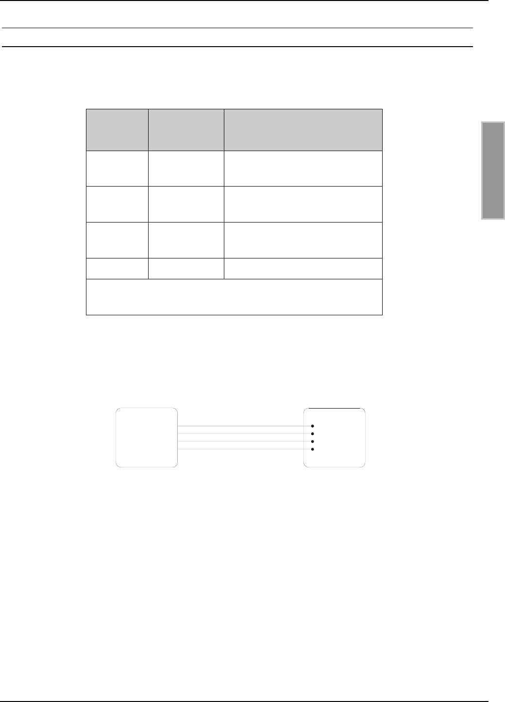
The transmission parameters for the interface can be software-configured. Table 4 shows the
standard parameters for the RS232 interface.
Parameter Standard setting
Baud rate 38400
No. of data bits 8
Parity Even
No. of stop bits 1
Table 4: Standard parameters of the RS232 interface.
Note:
• If there is an USB/RS232 converter used on the PC/Notebook side, we recommend to
increase the „Char Timeout Multiplier“ parameter in the COM-Port settings from „1“ to
about „10“.
• IF there is a RS232 to TTL converter used without external power supply it may be nec-
essary to switch on the COM Port parameter “RTS” and “DTR” manually.
OBID®Installation ID ISC.MU02.02
FEIG ELECTRONIC GmbH Page 28 of 36 M91002-0de-ID-B.doc
E N G L I S H
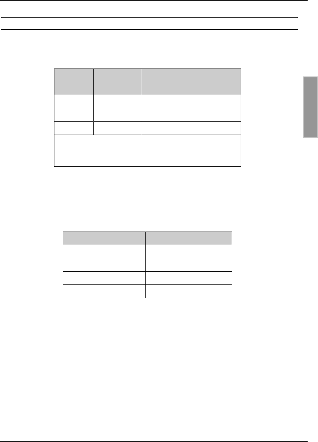
8.2.3. Data/Clock interface
The length of the cable to the data/clock interface should be kept as short as possible. It must not
exceed 3 m.
X2
Pin no. Function Description
1DAT Data line for the data/clock in-
terface
2CLK Clock line for the data/clock
interface
7CLS CLS line for the data/clock in-
terface
4, 9 GND * Ground
* GND-Pins 4 and 9 are to be connected directly to each
other on the Reader Module
Table 5: Pin configuration for the RS232 interface on Terminal X2
Fig. 3: Connecting the data/clock interface
Host
Data
Clock
CLS
GND
DAT
GND
CLK
CLS ID ISC.MU02
OBID®Installation ID ISC.MU02.02
FEIG ELECTRONIC GmbH Page 29 of 36 M91002-0de-ID-B.doc
E N G L I S H
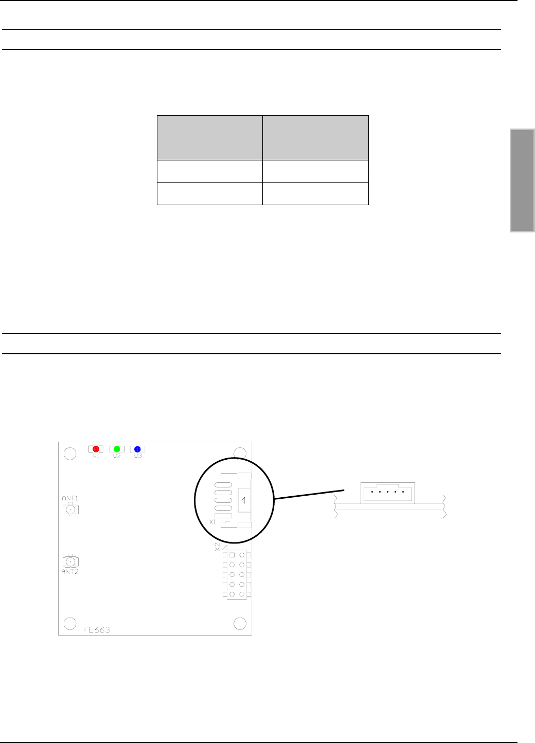
8.2.4. Shut Down
The ID ISC.MU02.02 can be switched off with the SHDN pin (pin no. 6 at terminal X2). Therefor the
pin has to be connected to Ground.
X2
Pin no. 6 Operating status
not connected on
Ground (GND) off
Table 9: Status table for the SHDN pin
Note:
• Supply voltages outside the specifications may destroy the device.
8.3. USB interface
Fig. 4 and Table 7 show the pin assignments for Terminal X1 (“JST PH” type with pitch 2.0 mm).
Fig. 7: Pin assignments for Terminal X1
15
OBID®Installation ID ISC.MU02.02
FEIG ELECTRONIC GmbH Page 30 of 36 M91002-0de-ID-B.doc
E N G L I S H
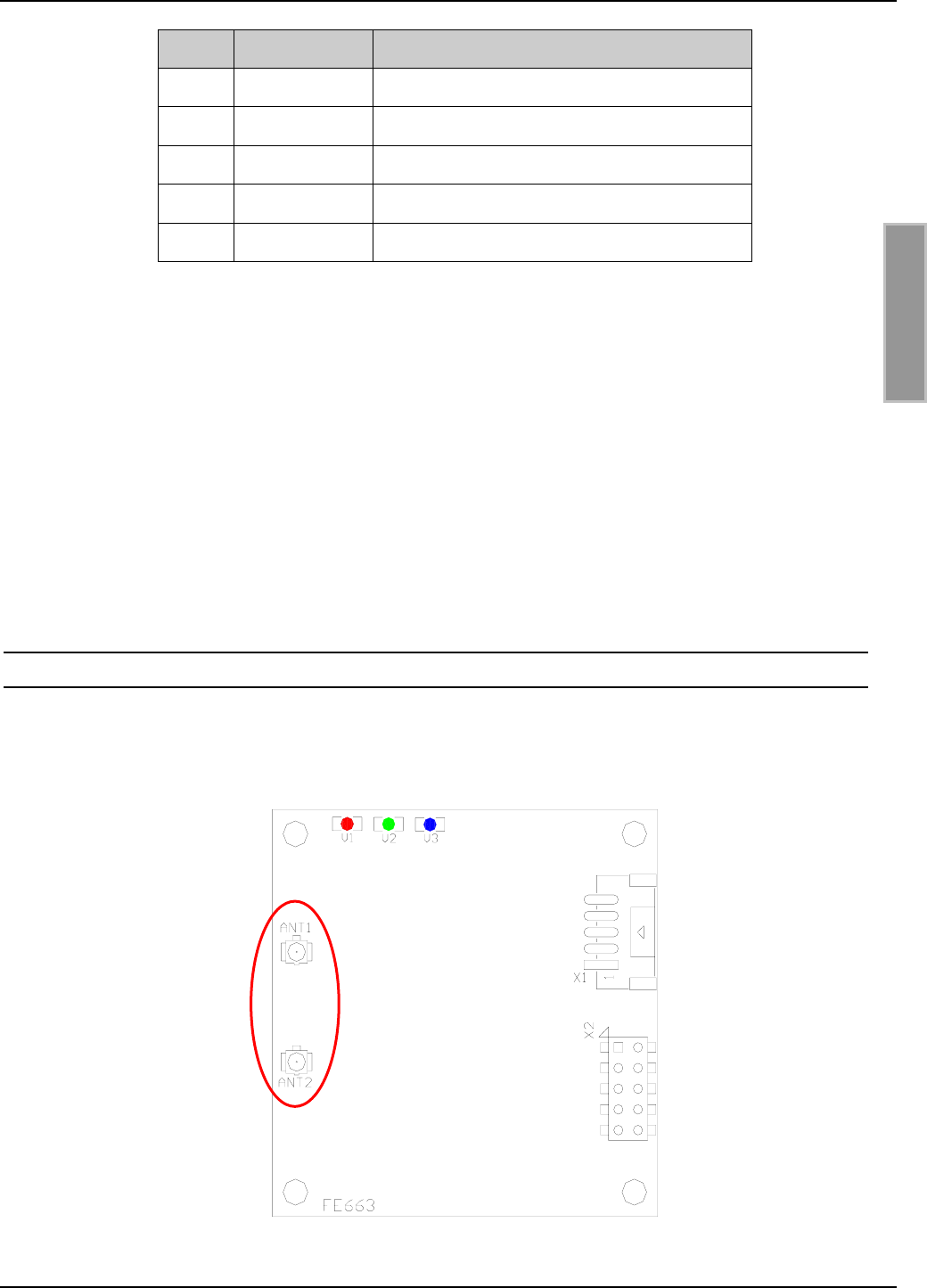
Pin Function Description
1SHIELD Shielding
2GND Ground
3D + USB-D PLUS
4D – USB-D MINUS
5VCC 5 V power supply
Table 10: Pin assignments for Terminal X1
The power supply follows though the USB-interface (Bus powered).
The USB interface must support a current of 500mA (High Powered Interface).
The data rate of the reader is reduced to 12 Mbit (USB high speed).
If the reader is used for the first time, it must be registered in the operating system of the computer.
For this the instruction "M70700-xde-ID-B: Installation OBID® USB driver" can be used.
Note:
• If the ID ISC.MU02.02 is USB powered there MUST NOT connected a power supply to
terminal X2.
8.4. Antenna ports
There can be 2 antennas connected to the ID ISC.MU02.02 at the antenna ports ANT1 and ANT2.
Fig. 5 shows the position of the “Hirose U.FL” receptacles with an input impedance of 50 Ω. The
antennas can be switched by software.
Fig. 5: Antenna ports ANT1 and ANT2
OBID®Installation ID ISC.MU02.02
FEIG ELECTRONIC GmbH Page 31 of 36 M91002-0de-ID-B.doc
E N G L I S H
8.5. Display elements
The ID ISC.MU02.02 Reader Module has a red LED (V1) and a green LED (V2) and a blue LED
(V3) which are used as display elements (Fig. 6).
Fig. 6: Position of the LEDs
The functions of both LEDs V2 and V3 can be configured using software protocol. It is also possi-
ble to control all 3 LEDs directly using an additional software protocol.

OBID®Installation ID ISC.MU02.02
FEIG ELECTRONIC GmbH Page 32 of 36 M91002-0de-ID-B.doc
E N G L I S H
Table 8 shows the standard setting for the LEDs.
LED Color Standard setting
V1 Red
• Flashes 5x after a reset.
• Off during normal operation.
• Flashing alternately with V2 during failure
status.
V2 Green
• Flashes 5x after a reset.
• On during normal operation.
• Off for 1 second after successful communica-
tion with a transponder.
• Flashing alternately with V1 during failure
status.
V3 Blue
• Flashes 10x after a reset.
• Comes on for 1 second after successful
communication with a transponder.
Table 8: Standard setting for the LEDs
8.6. Installation notes
Be aware of the following possible environmental factors when installing an ID ISC.MU02.02 into
another device :
• Effects from nearby metal objects
⇒ Detuning of the integrated antenna
⇒ Impaired propagation of the antenna’s electromagnetic field
• EMC effects on cables
⇒ Impaired communication between reader and transponder
8.6.1. Metallic surroundings
When installing an ID ISC.MU02.02 into another device, be sure that there are no metal surfaces
or objects in the direct vicinity of the connected antennas if possible. These can detune the an-
tenna and impair the propagation of the electromagnetic field due to reflections. This will in turn
result in reading holes and overshoots.
The distance between the antennas and a metal surface should be at least 5 cm. Note that
even other circuit boards may act line metal objects depending on how much copper they
contain.

OBID®Installation ID ISC.MU02.02
FEIG ELECTRONIC GmbH Page 33 of 36 M91002-0de-ID-B.doc
E N G L I S H
If a metallic surrounding cannot be avoided, stable function should at least be ensured by keeping
the distance as great as possible.
The area between the antenna and transponder as well as the area on the other side of the trans-
ponder should also be kept clear of metal parts.
8.6.2. EMC effects on cables
In spite of the internal EMC filters inside the reader, high levels of noise on the supply voltage can
result in impairment of the communication between the reader and transponder.
When installing an ID ISC.MU02.02 into another device, be sure therefore that a clean, noise-free
power supply is used.
9. Radio Approvals
9.1. Europe (CE)
When used according to regulation, this radio equipment conforms with the basic requirements of
Article 3 and the other relevant provisions of the R&TTE Guideline 1999/5/E6 dated March 99.
Equipment Classification gemäß ETSI EN 301 489: Class 2

OBID®Installation ID ISC.MU02.02
FEIG ELECTRONIC GmbH Page 34 of 36 M91002-0de-ID-B.doc
E N G L I S H
9.2. USA (FCC)
FCC ID: PJMMU02
This device complies with Part 15 of the FCC Rules. Operation is subject to the following
two conditions:
(1) this device may not cause harmful interference, and
(2) this device must accept any interference received, including interference that may
cause undesired operation.
NOTICE:
Changes or modifications made to this equipment not expressly approved by
FEIG ELECTRONIC GmbH may void the FCC authorization to operate this equipment.
This equipment has been tested and found to comply with the limits for a Class B digital
device, pursuant to Part 15 of the FCC Rules. These limits are designed to provide rea-
sonable protection against harmful interference in a residential installation. This equip-
ment generates, uses and can radiate radio frequency energy and, if not installed and
used in accordance with the instructions, may cause harmful interference to radio com-
munications. However, there is no guarantee that interference will not occur in a particular
installation. If this equipment does cause harmful interference to radio or television recep-
tion, which can be determined by turning the equipment off and on, the user is encour-
aged to try to correct the interference by one or more of the following measures:
-- Reorient or relocate the receiving antenna.
-- Increase the separation between the equipment and receiver.
-- Connect the equipment into an outlet on a circuit different from that to
which the receiver is connected.
-- Consult the dealer or an experienced radio/TV technician for help.
This device is labeled with an FCC ID number.
If this label is not visible when installed in an end device, the outside of the device MUST
also display a label referring to the enclosed module.
Wording on the label similar to the following shall be used:
This device contains transmitter module FCC ID PJMMU02
At the time of this printing, the antennas listed below were the only antennas approved for
use with the ID ISC.MU02.02 module. Use of other antennas must be approved by
FEIG ELECTRONIC GmbH.
Antennas approved: ID ISC.ANT.U170/170-FCC
ID ISC.ANT.U100/75-FCC
ID ISC.ANT.U75/50-FCC

OBID®Installation ID ISC.MU02.02
FEIG ELECTRONIC GmbH Page 35 of 36 M91002-0de-ID-B.doc
E N G L I S H
10. Technical Data
Mechanical Data
• Dimensions (W x H x D) 50 mm x 50 mm x 14 mm
(1,97 inch x 1,97 inch x 0,55 inch)
• Weight 10 g (0,02 lb)
• Connector • 10-pin connector, spacing 2.54 mm (0,1 inch)
• 5-pin connector,
type “JST PH” pitch 2 mm (0,079 inch)
Electrical Data
• Supply voltage 5 V DC ± 5%
• Power consumption max. 2 W
• Operating frequency 860 ... 960 MHz
• Transmitting power max. 170 mW ; reducible
• Antenna connection 2 x “Hirose U.FL” receptacles; 50 Ω; switchable
• Interfaces
- Variant AD
- Variant CU
RS232-V24, Data/Clock
RS232-LVTTL, USB

OBID®Installation ID ISC.MU02.02
FEIG ELECTRONIC GmbH Page 36 of 36 M91002-0de-ID-B.doc
E N G L I S H
Functional Properties
• Protocol Modes - FEIG ISO HOST
- Scan Mode
• Supported transponders EPC Class 1 Gen 2
• Visual indicators 3 LED (red / green / blue)
Ambient Conditions
• Temperature range
- Operation
- Storage
-25°C to +55°C (-13°F to 131°F)
-25°C to +85°C (-13°F to 185°F)
• Humidity 5 – 95% non condensing
Applicable Norms
• Radio approval
- Europe
- USA
EN 302 208
FCC 47 CFR Part 15
• EMC EN 301 489
• Safety EN 60950