Feig Electronic TSTPDFSASK Wireless Safety System for industrial doors User Manual PD FSAS 250 Eng 120102
Feig Electronic GmbH Wireless Safety System for industrial doors PD FSAS 250 Eng 120102
UserManual.pdf
FEIGELECTRONICGmbHLangeStr.4D‐35781Weilburg,GermanyTel.:+49(0)6471/3109‐0Fax:+49(0)6471/3109‐99www.feig.deEmail:info@feig.de
PD_FSAS‐250_Eng_120102.Doc
TSTPD_FSAS 250KBit
MultiturnAbsoluteEncoderw/integrated
WirelessSafetySystemforindustrialdoors
–StationaryUnit
MountingandStartupmanual
!ATTENTION
Thecontentofthedoorcontrollermanualandparticularlythesafetyinstructionsmustget
note!
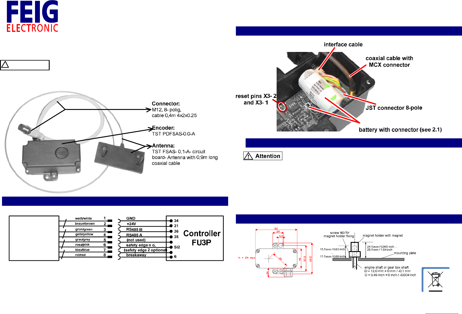
1. Pinconnections:
Remarks:
- ForconnectionshieldedcableswithM12A‐encodedplugarerecommended.Theshield
hastobeconnectedtoearthgroundonlyonthecontrollerside.
- Thehousingoftheplugisnotallowedtobeconnectedtoearthground.
- NotusedwiresmustbeisolatedinsideofFU3P
‐ Theassemblingtolerancefromshaftcentertosensorcenterismaximum+/‐1mm(+/‐
0.039inch).
- TorqueforM3screw/magnetholderfixing:maximum0.4Nm
2. Connectionimageinsidewith:
2.1batterychange:
Disconnectingthebatteryeffectsclearingofpositionvaluesfromtheencoder!After
reconnectingthebatteryaRESETmustbedone.Donotshortorchargethebattery.Do
notstoreoroperatethesystemabovethespecifiedtemperaturerange.Connecting
theencoderwithswitchedonsupplyvoltageisnotallowed.
)TodoanResetyoumustmakeanshortcutbetweentheResetpins
X3‐2andX3‐1forashortmoment
3. Mountingofencoder:
TST
PD_FSAS
250 KBit
FEIGELECTRONICGmbHLangeStr.4D‐35781Weilburg,GermanyTel.:+49(0)6471/3109‐0Fax:+49(0)6471/3109‐99www.feig.deEmail:info@feig.de
PD_FSAS‐250_Eng_120102.Doc
4. MountingofthestationaryAntenna:
Antenna
Mobile unit
Side view Front view
Antenna
Mobile unit
Figure:MountingofAntennaondoor
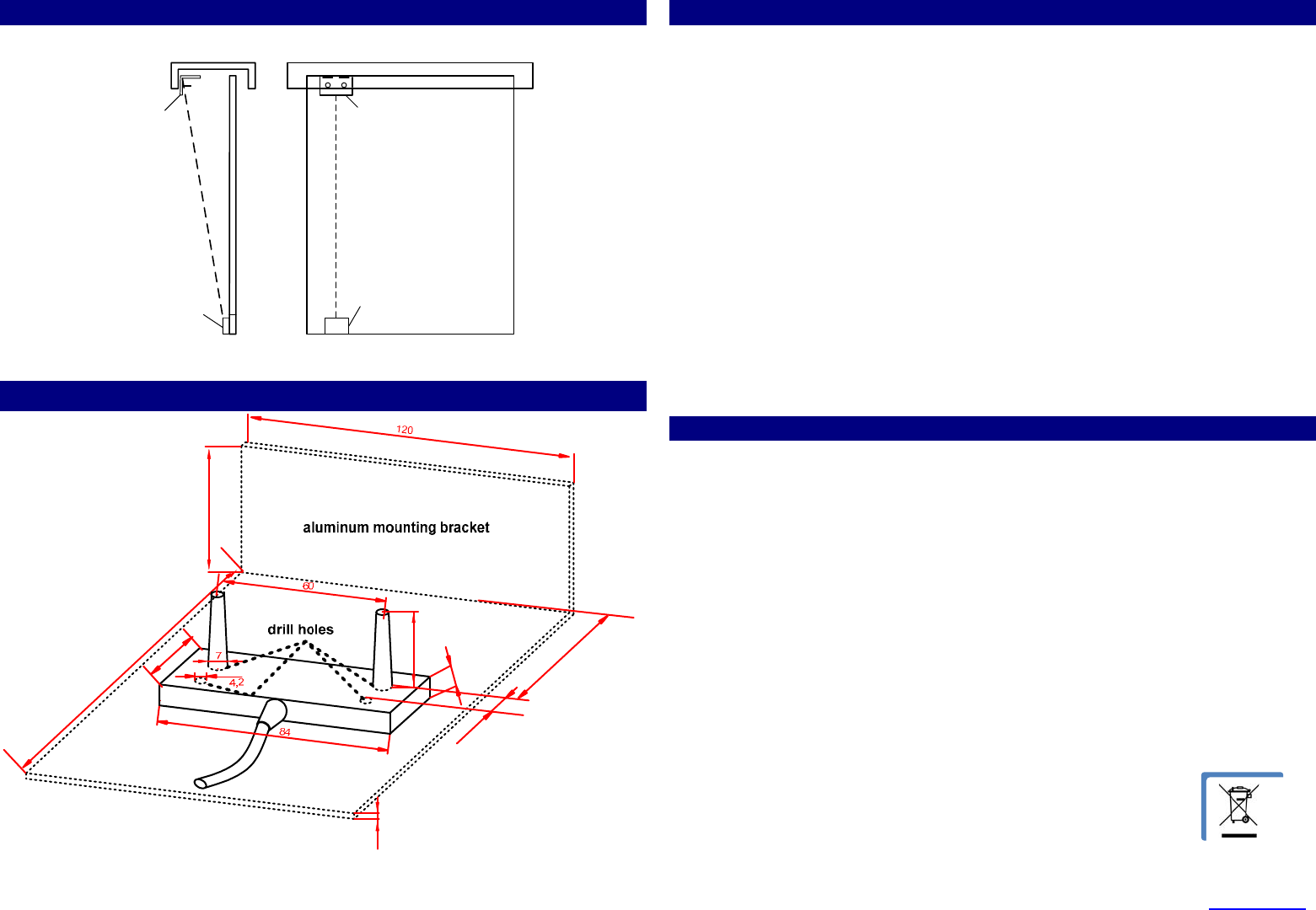
5. StationaryAntenna+aluminummountingbracket:
45
105
7,6
15
24,5
39
44
2
Figure:StationaryAntenna+aluminummountingbracket
6. TechnicalData:
Connectiondata:Supplyvoltage+24V+/‐10%,typical50mA.
SerialbidirectionalInterfaceRS485/19,2kBaud
Digitaloutputs:Threeconfigurableoutputswiththefollowingstandardsetting:
- Output1and2:Safetyoutput(N.O.)with8.2kΩterminalresistorand
testingofterminalresistor.
- Output3:Breakawayoutput
(N.C.contactat24Vwith560Ωlimitingresistor)
ConnectingtoA‐encodedM12plugwith35cmlongcable.
Themax.allowedLengthofthecustomermountedcableis50m
Radio: Operatingrange2400to2483.5MHz
40channels,Ratedoutputpower0dBm
Temperaturerange: Operatingrange–40to+70°C,
Storagerange–40to+70°C(recommended+20°C)
Protectionclass: IP65
Max.tolerablespeed:6000U/min
Resolution:13Bit/turn(8192Increments/turn)
Counterofturns:15Bit
Weight: Withoutcablebutwithmagnetholder220g
Lifetimeofbattery:typical10years
Dimensions(LxBxH):Encoder92x69.5x24mm
Antennaboard84x39x7.6mm(Antennaheight26mm)
7. FCCStatements:
Notice:ThisdevicecomplieswithPart15oftheFCCRulesandwithRSS‐210ofIndustryCanada.
Operationissubjecttothefollowingtwoconditions:
(1)thisdevicemaynotcauseharmfulinterference,and
(2)thisdevicemustacceptanyinterferencereceived,includinginterferencethatmaycause
undesiredoperation.
Notice:Changesormodificationsmadetothisequipmentnotexpresslyapprovedby
FEIGELECTRONICmayvoidtheFCCauthorizationtooperatethisequipment.
Notice:ThisproducthasbeentestedandfoundtocomplywiththelimitsforaClassBdigitaldevice,
pursuanttopart15oftheFCCRules.Theselimitsaredesignedtoprovidereasonableprotection
againstharmfulinterferenceinaresidentialinstallation.Thisequipmentgeneratesusesandcan
radiateradiofrequencyenergyand,ifnotinstalledandusedinaccordancewiththeinstructions,may
causeharmfulinterferencetoradiocommunications.However,thereisnoguaranteethat
interferencewillnotoccurinaparticularinstallation.Ifthisequipmentdoescauseharmful
interferencetoradioortelevisionreception,whichcanbedeterminedbyturningtheequipmentoff
andon,theuserisencouragedtotrytocorrecttheinterferencebyoneormoreofthefollowing
measures:
‐ Reorientorrelocatethereceivingantenna
‐ Increasetheseparationbetweentheequipmentandreceiver
‐ Connecttheequipmentintoanoutletonacircuitdifferentfromthattowhich
thereceiverisconnected
‐ Consultthedealeroranexperiencedradio/TVtechnicianforhelp