Fibar Group FGK10XZ5 Door Window Sensor User Manual
Fibar Group S.A. Door Window Sensor
UserManual.wiki
>
Fibar Group
>
FGK10XZ5 User Manual
User manual
Navigation menu
Upload a User Manual
Namespaces
Wiki Guide
HTML
PDF
Info
Views
User Manual
Discussion / Help
Navigation
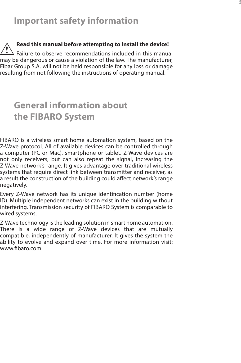
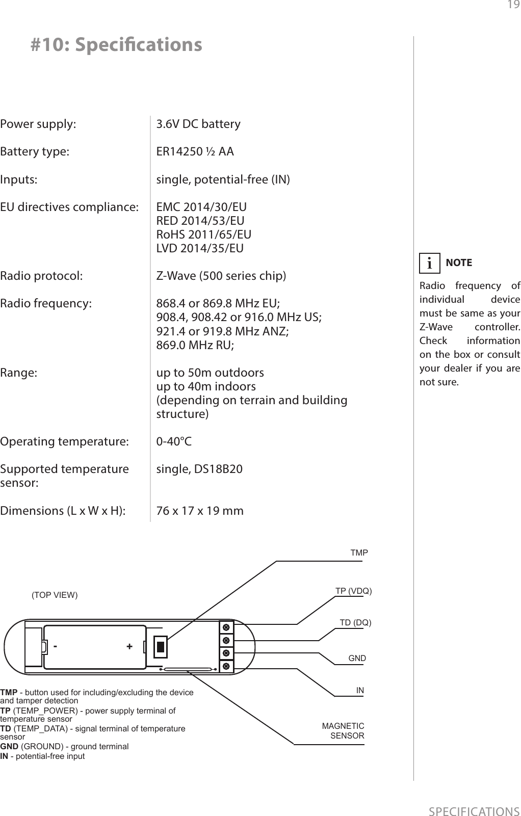
![13ADVANCED PARAMETERS#9: Advanced parametersThe Door/Window Sensor allows to customize its operation to user’s needs. Settings are available in the FIBARO interface as simple op-tions that may be chosen by selecting the appropriate box.In order to congure the Door/Window Sensor (using the Home Center controller):1. Go to the device options by clicking the icon: 2. Select the „Advanced” tab.1. Operation modeParameter denes device operation mode.Available settings: 0 - Door/Window Sensor or external alarm sensor1 - external buttonDefault setting: 0Parameter size: 1 [byte]2. Door/Window or alarm statusParameter denes state of the sensor when the magnet is close. If the alarm sensor is connected, it determines the output type. Parameter inactive in external button mode (parameter 1 set to 1). Available settings: 0 - door/window closed1 - door/window openedDefault setting: 0Parameter size: 1 [byte]Wake up intervalAvailable settings: 0 or 3600-64800 (in seconds, 1h - 18h)Default setting: 21 600 (every 6 hours)The Door/Window Sensor will wake up after each dened time inter-val and always try to connect with the main controller. After a suc-cessful communication attempt, the sensor will update conguration parameters, associations and settings and will go into standby mode. After failed communication attempt (e.g. lack of Z-Wave range) the device will go into standby mode and retry to establish connection with the main controller after the next time interval.Setting wake up interval to 0 disables sending Wake Up Notication frame automatically. Wake up may be still performed manually by a single TMP button click.Longer time interval means less frequent communication and thus a longer battery life.CAUTIONDo not install the magnet if the de-vice is not used as a Door/Window Sensor, as it might lead to the malfunction of the device.!](https://usermanual.wiki/Fibar-Group/FGK10XZ5/User-Guide-3090174-Page-13.png)
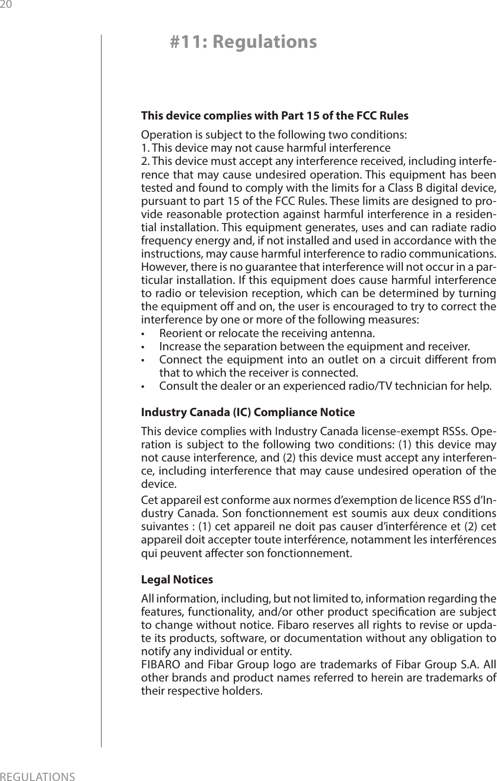
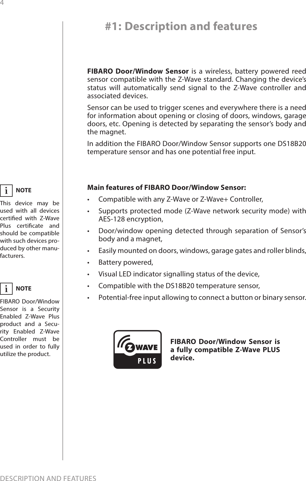
![14ADVANCED PARAMETERS3. Visual LED indicationsThis parameter denes events indicated by the visual LED indicator. Disabling events might extend battery life.Available settings: 0 - no indications1 - indication of opening/closing status change (input IN)2 - indication of wake up (1 x click or periodical)4 - indication of device tamperingDefault setting: 6Parameter size: 1 [byte]4. Range test after double clickAllows to enable activation of Z-Wave range test with double click of a TMP button.Available settings: 0 - disabled1 - enabledDefault setting: 0Parameter size: 1 [byte]10. 2nd association group triggersParameter denes events which result in sending on/o commands to devices added to the 2nd association group. These commands are sent alternately to switch the devices on and o. Commands repre-sent the values of BASIC SET command frames. Parameter is inactive in external button mode (parameter 1 set to 1). Available settings: 0 - switch after opening and closing1 - switch after opening2 - switch after closingDefault setting: 0Parameter size: 1 [byte]11. Commands sent to 2nd association groupCommand frames sent to devices added to the 2nd association group.Available settings: 0 - ON1 - OFF2 - ON & OFFDefault setting: 2Parameter size: 1 [byte]12. Value of ON command frame sent to 2nd association groupThe value of 0 turns OFF the device, 255 turns it ON. In case of asso-ciating the Dimmer or Roller Shutter module, values 1-99 allow to set an associated device to a specied level.Available settings: 0-99 or 255Default setting: 255 Parameter size: 2 [bytes]NOTEValues of parameter 3 may be combined, e.g. 1+2=3 means opening/closing and wake up will be indi-cated by the visual in-dicator.i](https://usermanual.wiki/Fibar-Group/FGK10XZ5/User-Guide-3090174-Page-14.png)
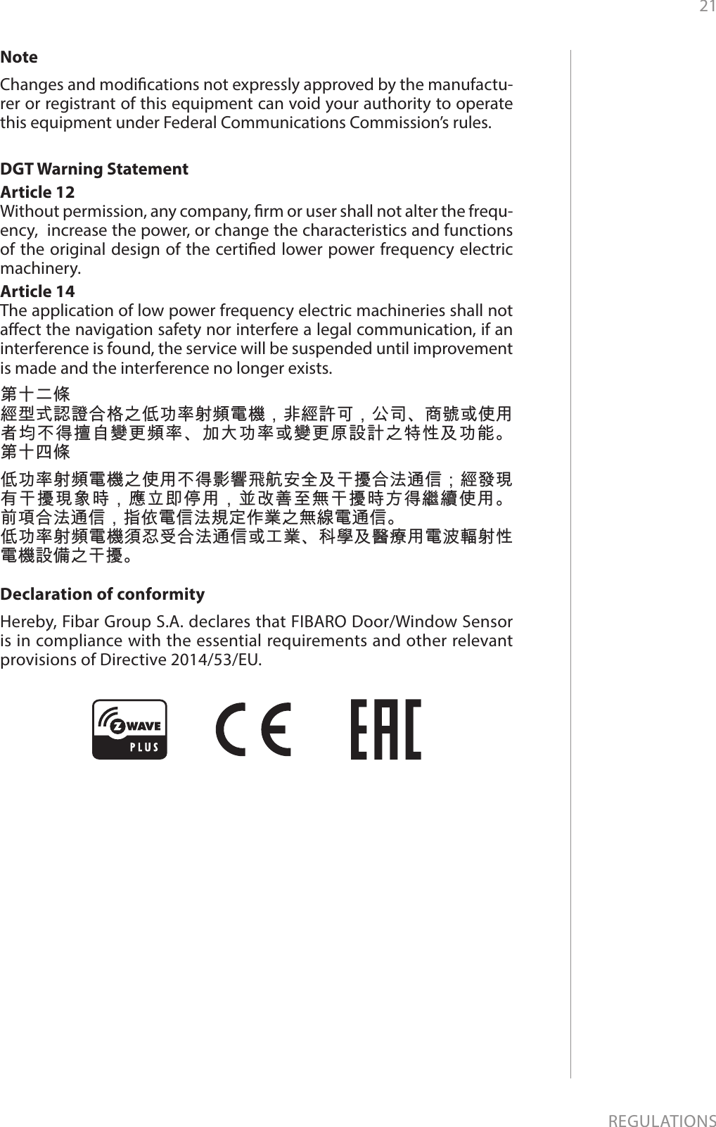
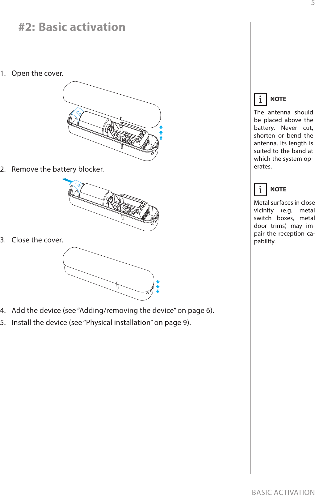
![15ADVANCED PARAMETERS13. Value of OFF command frame sent to 2nd association groupThe value of 0 turns OFF the device, 255 turns it ON. In case of asso-ciating the Dimmer or Roller Shutter module, values 1-99 allow to set an associated device to a specied level.Available settings: 0-99 or 255Default setting: 0Parameter size: 2 [bytes]14. Time delay of ON command frameTime period after which ON command frame will be sent.Available settings: 0-32400 - time in secondsDefault setting: 0Parameter size: 2 [bytes]15. Time delay of OFF command frameTime period after which OFF command frame will be sent.Available settings: 0-32400 - time in secondsDefault setting: 0Parameter size: 2 [bytes]20. Type of sent alarm framesType of control frames transmitted to the main controller and 3rd as-sociation group “Alarm”. If an external sensor is connected to IN input, it is possible to choose its functionality. Otherwise it is recommended to set this parameter to default value.Available settings: 0 - Door/Window Sensor (General Purpose Alarm)1 - smoke sensor (Smoke Alarm)2 - CO detector (CO Alarm)3 - CO2 detector (CO2 Alarm)4 - high temperature sensor (Heat Alarm)5 - ood sensor (Water Alarm)Default setting: 0Parameter size: 1 [byte]30. Delay of tamper alarm cancellationTime period after which a tamper alarm will be cancelled.Available settings: 0-32400 - time in secondsDefault setting: 5Parameter size: 2 [bytes]31. Reporting tamper alarm cancellationReporting cancellation of tamper alarm to the controller and 5th as-sociation group.Available settings: 0 - do not send tamper cancellation report1 - send tamper cancellation reportDefault setting: 1Parameter size: 1 [byte]CAUTIONIn order to activate new settings of pa-rameter 20, it is re-quired to remove and re-add the device to the main Z-Wave con-troller. This parameter is not reset during re-moval process.!](https://usermanual.wiki/Fibar-Group/FGK10XZ5/User-Guide-3090174-Page-15.png)
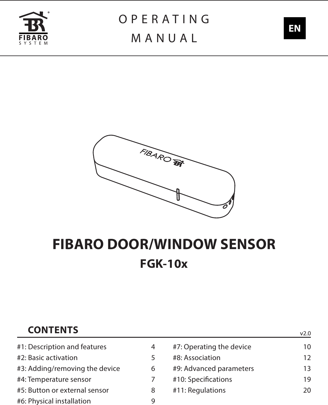
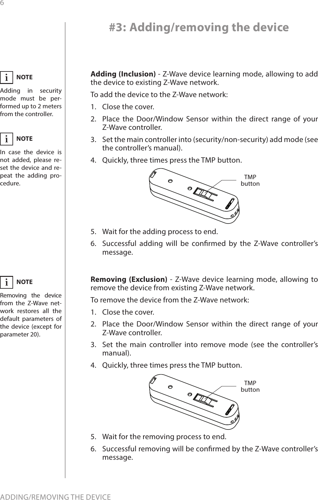
![16ADVANCED PARAMETERS50. Interval of temperature measurementsThis parameter denes how often the temperature will be measured. The shorter the time, the more frequently the temperature will be measured, but the battery life will shorten.Available settings: 0 - temperature measurements disabled5-32400 - time in secondsDefault setting: 300 (5min) Parameter size: 2 [bytes]51. Temperature reports thresholdThis parameter denes the change of temperature in comparison with last reported, resulting in temperature report being sent to the main controller.Available settings:0 - temperature reports based on threshold disabled1-300 - temperature threshold (0.1-30°C, 0.1°C step)Default setting: 10 (1°C )Parameter size: 2 [bytes]52. Interval of temperature reportsThis parameter determines how often the temperature reports will be sent to the main controller.Available settings: 0 - periodic temperature reports disabled5-32400 - time in secondsDefault setting: 0Parameter size: 2 [bytes]53. Temperature osetThe value to be added to the actual temperature, measured by the sen-sor (temperature compensation).Available settings: -1000-1000 (-100-100°C, 0.1°C step)Default setting: 0 (0°C )Parameter size: 4 [bytes]54. Temperature alarm reportsTemperature alarms reported to the Z-Wave controller. Thresholds are set in parameters 55 and 56.Available settings: 0 - temperature alarms disabled1 - high temperature alarm2 - low temperature alarm3 - high and low temperature alarms enabledDefault setting: 0Parameter size: 1 [byte]55. High temperature alarm thresholdIf temperature is higher than set value, overheat notication will be sent and high temperature scene will be triggered (if activated).Available settings: 0-1000 (0-100°C, 0.1°C step)Default setting: 540 (54°) Parameter size: 2 [bytes]NOTEParameter 51 is active only if parameter 50 is not set to 0.iNOTETemperature meas-urement is performed before sending any report (regardless of parameter no. 50). Ex-cessive reporting can aect battery lifetime. Reporting on the ba-sis of temperature change (parameter no. 51) is recommend-ed.i](https://usermanual.wiki/Fibar-Group/FGK10XZ5/User-Guide-3090174-Page-16.png)
![17ADVANCED PARAMETERS56. Low temperature alarm thresholdIf temperature is lower than the set value, underheat notication will be sent and low temperature scene will be triggered (if activated).Available settings: -300-700 (-30-70°C, 0.1°C step)Default setting: 40 (4°) Parameter size: 2 [bytes]70. Scene activation functionalityThe device can trigger scenes using scene IDs assigned to dierent events. To deactivate all scenes set the value to 0. To activate all scenes set the value to 3903.Available settings: 1 - [ID 10] opening door/window (single click)2 - [ID 11] closing door/window (single click)4 - [ID 12] holding8 - [ID 13] releasing16 - [ID 14] double click32 - [ID 15] triple click256 - [ID 50] high temperature - door/window opened512 - [ID 50] high temperature - door/window closed1024 - [ID 51] low temperature - door/window opened2048 - [ID 51] low temperature - door/window closedDefault setting: 0 (none) Parameter size: 2 [bytes]71. Alarm broadcastSettings for broadcasting ON/OFF commands, sensor alarm and tam-per alarm. Value other than 0 means alarms are sent in Broadcast Mode, to all devices only within the range of the device. They are not repeated by the mesh network.Available settings: 0 - broadcasts inactive1 - ON/OFF commands broadcast active2 - sensor alarm broadcast active4 - tamper alarm broadcast activeDefault setting: 0 (inactive) Parameter size: 1 [byte]CAUTIONEvery activated scene may shorten the bat-tery life.!NOTEValues of parameter 71 may be combined, e.g. 1+2=3 means ON/OFF commands and sensor alarm are sent in Broadcast Mode.iNOTEValues of parameter 70 may be combined, e.g. 1+2=3 means scenes for opening and closing are sent.iNOTEScenes with IDs 12 to 15 are active only if parameter 1 is set to 1. In this case scenes with IDs 1 and 2 are sent after a single click.i](https://usermanual.wiki/Fibar-Group/FGK10XZ5/User-Guide-3090174-Page-17.png)
![18ADVANCED PARAMETERS72. Associations in Z-Wave network Security ModeThis parameter denes how commands are sent in specied associa-tion groups: as secure or non-secure. Parameter is active only in Z-Wave network security mode. It does not apply to 1st group “Lifeline”.Available settings: 0 - none of the groups sent as secure1 - 2nd group ”Control” sent as secure2 - 3rd group ”Alarm” sent as secure4 - 4th group “Sensor ZW3” sent as secure8 - 5th group “Tamper ZW3” sent as secureDefault setting: 15 (all) Parameter size: 1 [byte]NOTEOperating in Z-Wave network security mode automatical-ly disables sending alarms in broadcast mode.iNOTEValues of parameter 72 may be combined, e.g. 1+2=3 means 2nd and 3rd group are sent as secure.i](https://usermanual.wiki/Fibar-Group/FGK10XZ5/User-Guide-3090174-Page-18.png)