Fibar Group FGK10XZ5 Door Window Sensor User Manual
Fibar Group S.A. Door Window Sensor
User manual
FIBARO DOOR/WINDOW SENSOR
FGK-10x
CONTENTS
#1: Description and features 4
#2: Basic activation 5
#3: Adding/removing the device 6
#4: Temperature sensor 7
#5: Button or external sensor 8
#6: Physical installation 9
#7: Operating the device 10
#8: Association 12
#9: Advanced parameters 13
#10: Specications 19
#11: Regulations 20
OPERATING
MANUAL EN
v2.0

3
Important safety information
Read this manual before attempting to install the device!
Failure to observe recommendations included in this manual
may be dangerous or cause a violation of the law. The manufacturer,
Fibar Group S.A. will not be held responsible for any loss or damage
resulting from not following the instructions of operating manual.
!
General information about
the FIBARO System
FIBARO is a wireless smart home automation system, based on the
Z-Wave protocol. All of available devices can be controlled through
a computer (PC or Mac), smartphone or tablet. Z-Wave devices are
not only receivers, but can also repeat the signal, increasing the
Z-Wave network’s range. It gives advantage over traditional wireless
systems that require direct link between transmitter and receiver, as
a result the construction of the building could aect network’s range
negatively.
Every Z-Wave network has its unique identication number (home
ID). Multiple independent networks can exist in the building without
interfering. Transmission security of FIBARO System is comparable to
wired systems.
Z-Wave technology is the leading solution in smart home automation.
There is a wide range of Z-Wave devices that are mutually
compatible, independently of manufacturer. It gives the system the
ability to evolve and expand over time. For more information visit:
www.baro.com.

4
DESCRIPTION AND FEATURES
Main features of FIBARO Door/Window Sensor:
• Compatible with any Z-Wave or Z-Wave+ Controller,
• Supports protected mode (Z-Wave network security mode) with
AES-128 encryption,
• Door/window opening detected through separation of Sensor’s
body and a magnet,
• Easily mounted on doors, windows, garage gates and roller blinds,
• Battery powered,
• Visual LED indicator signalling status of the device,
• Compatible with the DS18B20 temperature sensor,
• Potential-free input allowing to connect a button or binary sensor.
FIBARO Door/Window Sensor is a wireless, battery powered reed
sensor compatible with the Z-Wave standard. Changing the device’s
status will automatically send signal to the Z-Wave controller and
associated devices.
Sensor can be used to trigger scenes and everywhere there is a need
for information about opening or closing of doors, windows, garage
doors, etc. Opening is detected by separating the sensor’s body and
the magnet.
In addition the FIBARO Door/Window Sensor supports one DS18B20
temperature sensor and has one potential free input.
#1: Description and features
FIBARO Door/Window Sensor is
a fully compatible Z-Wave PLUS
device.
NOTE
This device may be
used with all devices
certied with Z-Wave
Plus certicate and
should be compatible
with such devices pro-
duced by other manu-
facturers.
i
NOTE
FIBARO Door/Window
Sensor is a Security
Enabled Z-Wave Plus
product and a Secu-
rity Enabled Z-Wave
Controller must be
used in order to fully
utilize the product.
i
5
BASIC ACTIVATION
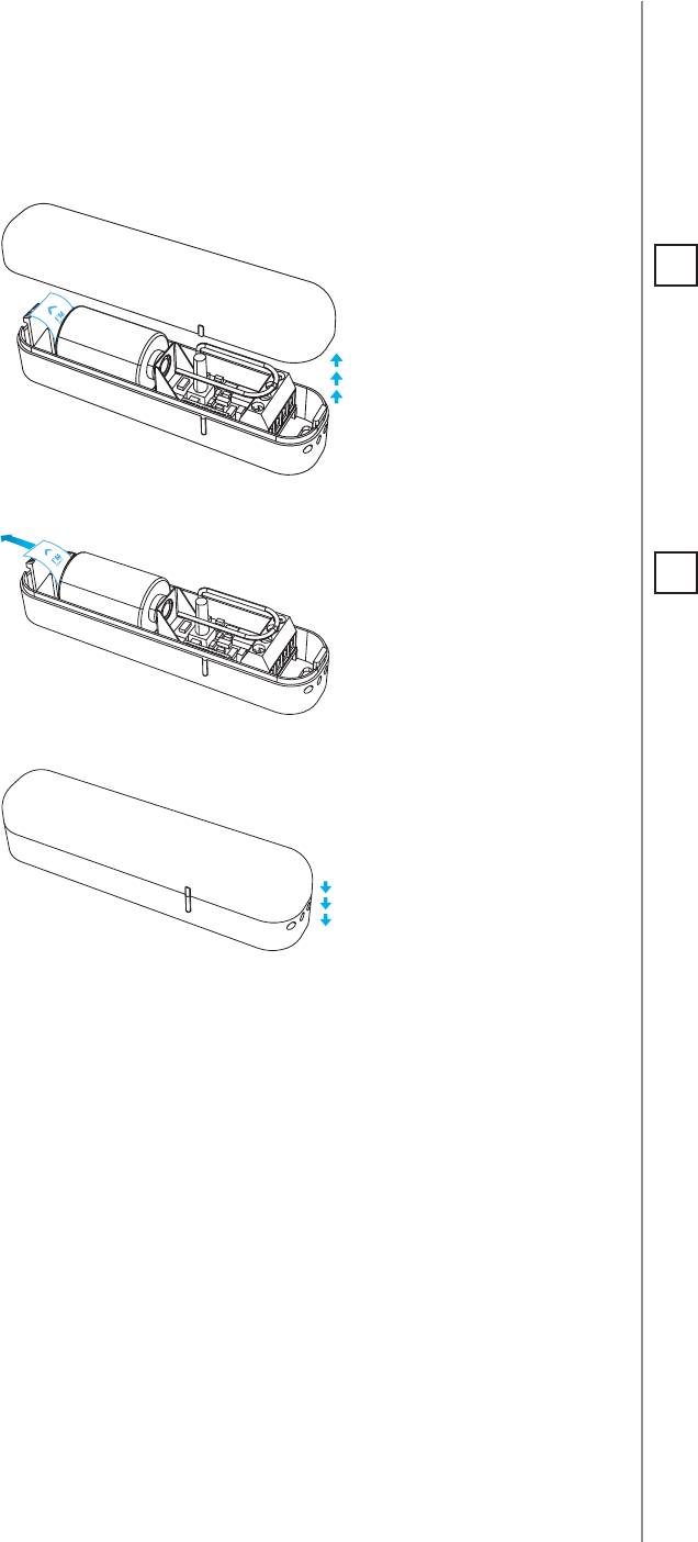
#2: Basic activation
1. Open the cover.
2. Remove the battery blocker.
3. Close the cover.
4. Add the device (see “Adding/removing the device” on page 6).
5. Install the device (see “Physical installation” on page 9).
NOTE
The antenna should
be placed above the
battery. Never cut,
shorten or bend the
antenna. Its length is
suited to the band at
which the system op-
erates.
i
NOTE
Metal surfaces in close
vicinity (e.g. metal
switch boxes, metal
door trims) may im-
pair the reception ca-
pability.
i
6
ADDING/REMOVING THE DEVICE
#3: Adding/removing the device
Adding (Inclusion) - Z-Wave device learning mode, allowing to add
the device to existing Z-Wave network.
To add the device to the Z-Wave network:
1. Close the cover.
2. Place the Door/Window Sensor within the direct range of your
Z-Wave controller.
3. Set the main controller into (security/non-security) add mode (see
the controller’s manual).
4. Quickly, three times press the TMP button.
5. Wait for the adding process to end.
6. Successful adding will be conrmed by the Z-Wave controller’s
message.
Removing (Exclusion) - Z-Wave device learning mode, allowing to
remove the device from existing Z-Wave network.
To remove the device from the Z-Wave network:
1. Close the cover.
2. Place the Door/Window Sensor within the direct range of your
Z-Wave controller.
3. Set the main controller into remove mode (see the controller’s
manual).
4. Quickly, three times press the TMP button.
5. Wait for the removing process to end.
6. Successful removing will be conrmed by the Z-Wave controller’s
message.
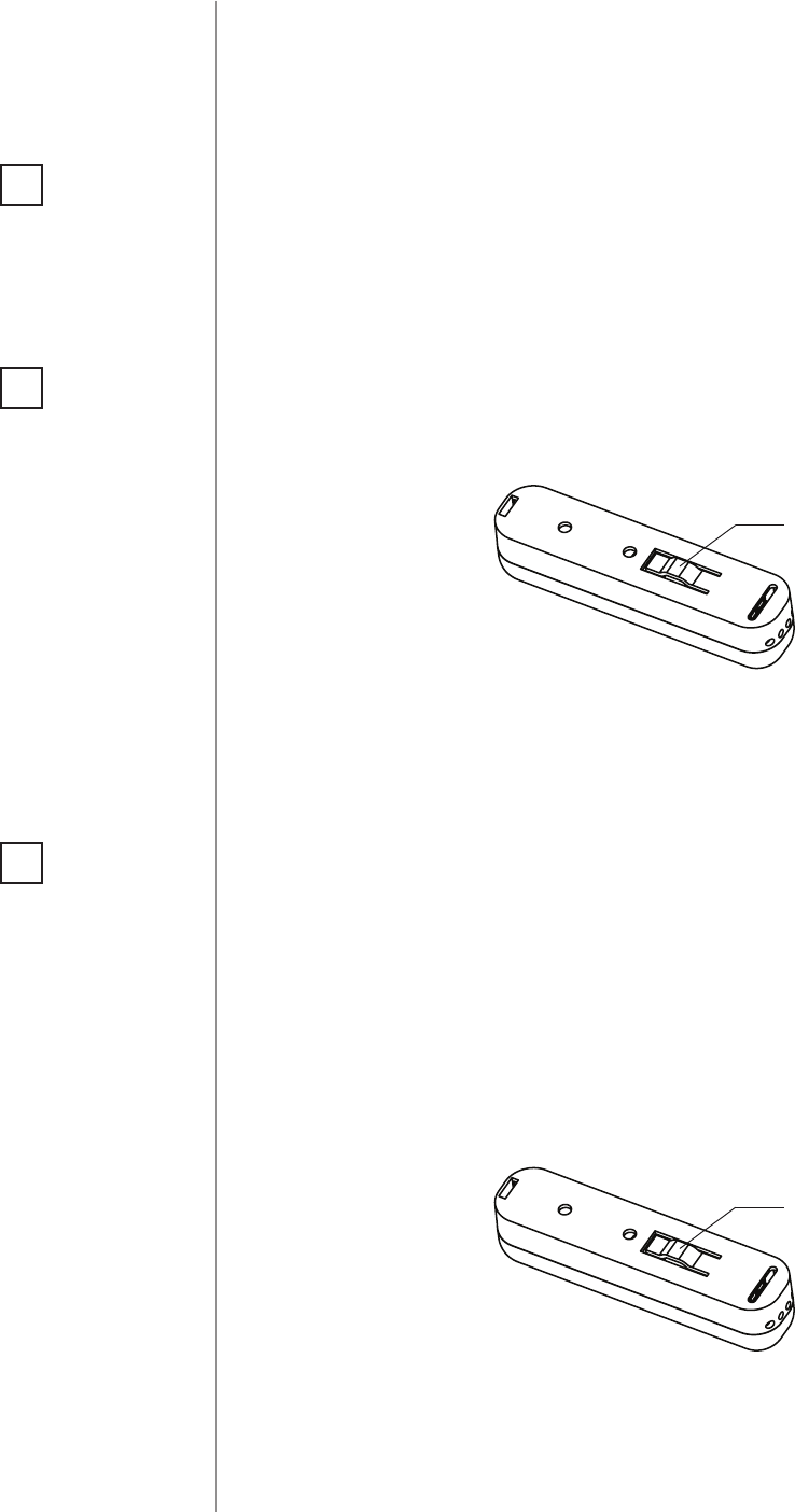
TMP
button
NOTE
Adding in security
mode must be per-
formed up to 2 meters
from the controller.
i
NOTE
Removing the device
from the Z-Wave net-
work restores all the
default parameters of
the device (except for
parameter 20).
i
NOTE
In case the device is
not added, please re-
set the device and re-
peat the adding pro-
cedure.
i
TMP
button
7
TEMPERATURE SENSOR
#4: Temperature sensor
CAUTION
Connected the device
in accordance with
the wiring diagram.
Incorrect wiring may
be dangerous or result
in the device break-
down.
!
NOTE
Connecting/discon-
necting the temper-
ature sensor to/from
previously added
Door/Window Sensor,
requires removing
and re-adding the
device to the Z-Wave
network.
i
The DS18B20 temperature sensor may be installed anywhere where
temperature readouts are necessary. If adequately protected, the
DS18B20 sensor may be installed in humid conditions, under water,
sealed in concrete or placed under the oor.
CAUTION
Connecting devic-
es and sensors other
than DS18B20 is not
allowed.
!
To activate the device with temperature measurement functionality:
1. Open the cover.
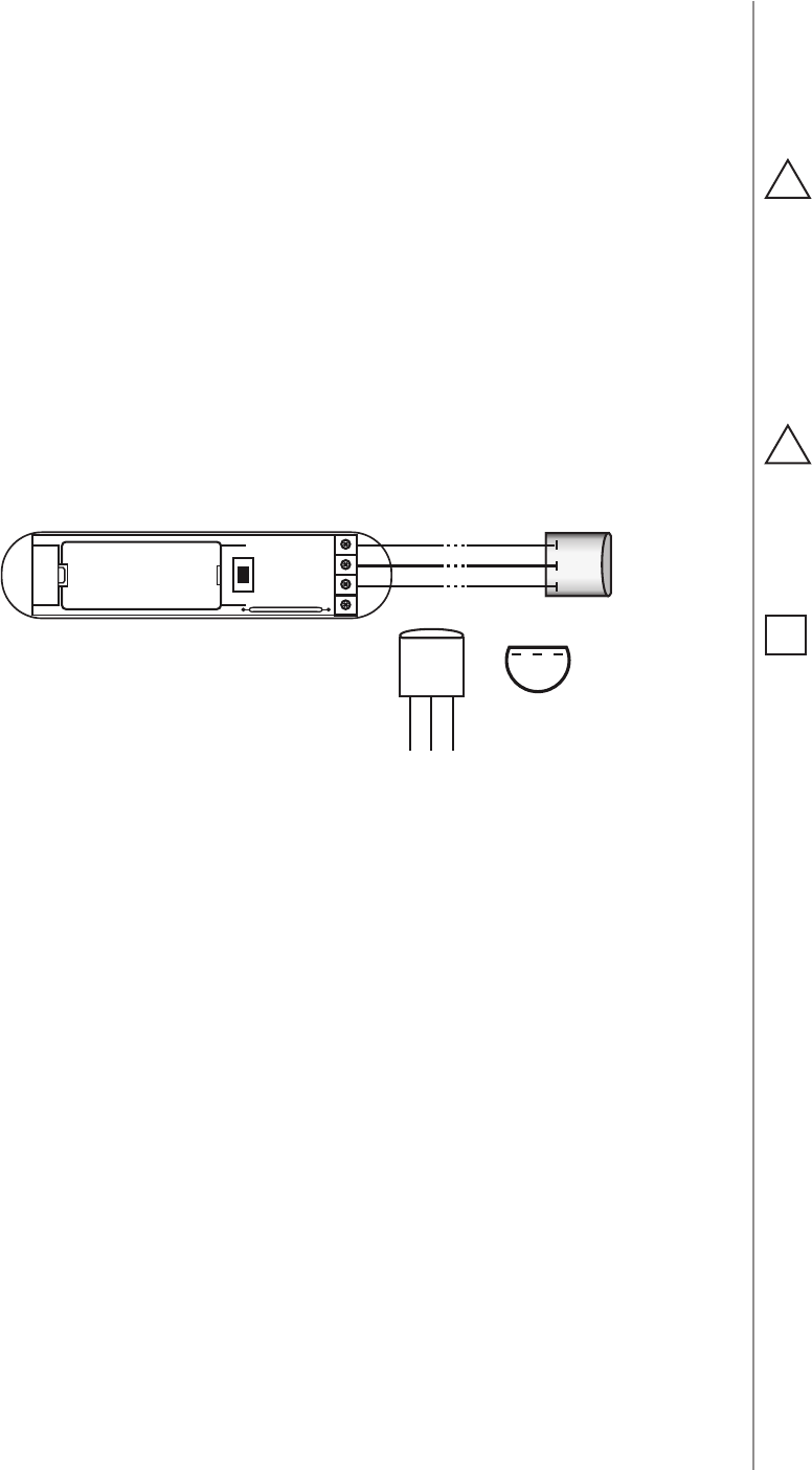
2. Connect the temperature sensor to terminals of the device
according to the diagram:
3. Add the device (see “Adding/removing the device” on page 6).
4. Install the device (see “Physical installation” on page 9).
GND
max 30m
TD (DQ)
TP (VDQ)
321
(BOTTOM VIEW)
(TOP VIEW)
TMP
DS18B20
123
321
GND
TD (DQ)
TP (VDQ)
DS18B20
+
-
TP
(TEMP_POWER) - power supply terminal of
temperature sensor
TD
(TEMP_DATA) - signal terminal of temperature sensor
GND
(GROUND) - ground terminal
8
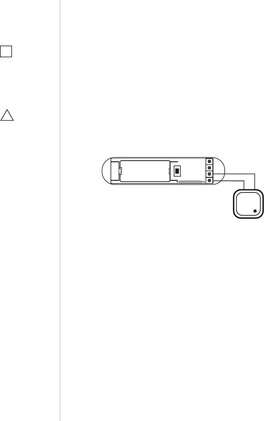
BUTTON OR EXTERNAL SENSOR
#5: Button or external sensor
Door/Window Sensor is equipped with a potential-free input. It allows
to change device state using the external button or sensor through
GND signal.
If the Door/Window Sensor will be used only as a binary sensor, do
not install the magnet.
To activate the device as a binary sensor:
1. Open the cover.
2. Connect the button or external sensor to terminals of the device
according to diagram:
3. Add the device (see “Adding/removing the device” on page 6) if
the device is not already added.
4. In case of connecting external sensor modify advanced parameter
no. 20 to match type of the sensor, then remove and re-add the
device to the network.
5. Install the device (see “Physical installation” on page 9).
IN
GND
MOMENTARY SWITCH
(TOP VIEW)
TMP
+
-
GND
(GROUND) - ground terminal
IN
- potential-free input
NOTE
Potential-free input is
a type of input contact
which does not have
a voltage on it after
closing.
i
CAUTION
Connected the device
in accordance with
the wiring diagram.
Incorrect wiring may
be dangerous or result
in the device break-
down.
!
9
PHYSICAL INSTALLATION
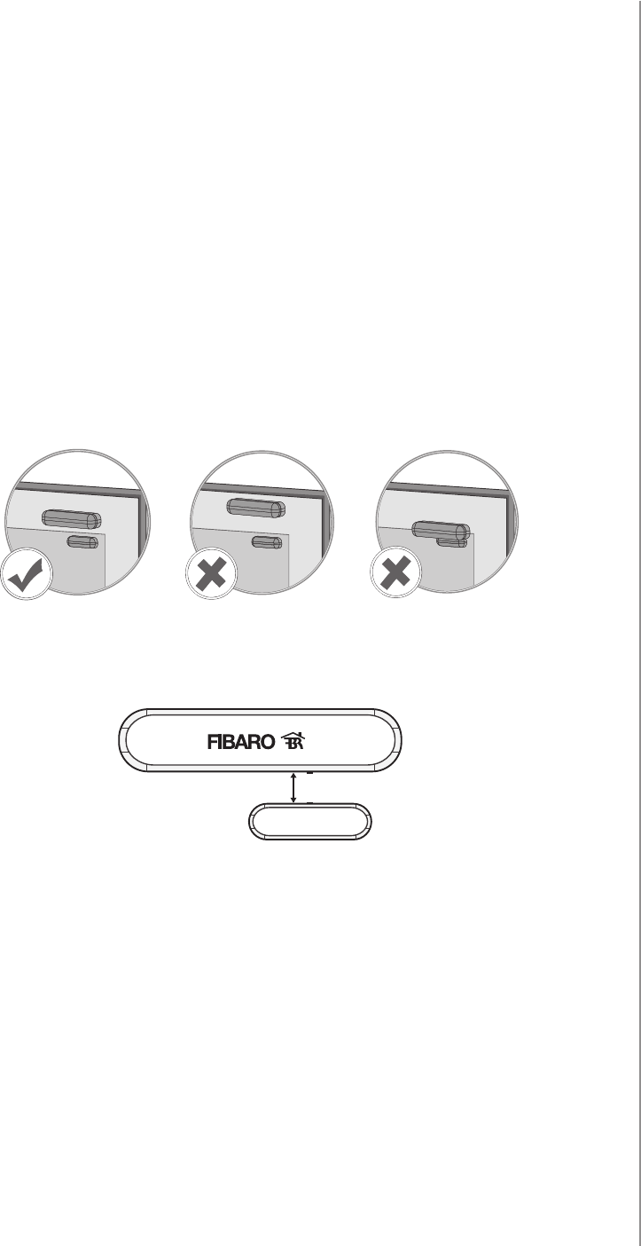
#6: Physical installation
To install the Door/Window Sensor:
1. Stick the included self-adhesive pads to the bottom of the device
and magnet.
2. Peel o the protective layer of the sticker.
3. Stick the device onto the door/window frame.
4. Stick the magnet onto the moving part of the door/window, no
further than 5mm from the sensor.
max. 5 mm
Correct postioning of the magnet in relation to the Sensor:
Positioning of the Sensor and the magnet:
10
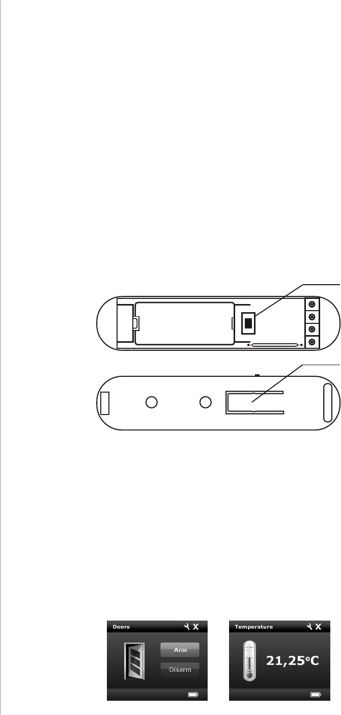
OPERATING THE DEVICE
#7: Operating the device
Controlling the Door/Window Sensor with FIBARO Home Center
controller:
After adding the Sensor to the FIBARO System, it will be represented
by one or two icons in Home Center interface.
Sensor without connected DS18B20 sensor or used with a button
connected to IN input (without magnet), will be represented by a sin-
gle icon.
In case of connecting DS18B20 temperature sensor, the additional
temperature sensor icon will be displayed.
Tamper (TMP) button:
The Door/Window Sensor is equipped with a tamper switch with two
buttons.
First TMP button is located inside the device, pressed by the closed
cover. Second TMP button is located at bottom of the device, pressed
by the surface on which the device is mounted.
For the tamper switch to work one of the buttons must always be
pressed!
When one of the buttons is released, the tamper alarm will be send to
the controller and associated devices.
Additionally, tamper button allows to control the device directly.
TMP
(TOP VIEW)
(BOTTOM VIEW) TMP
+
-

11
OPERATING THE DEVICE
Resetting the Door/Window Sensor:
Reset procedure deletes EEPROM’s memory, including all information
on the Z-Wave network and the main controller.
1. Open the cover.
2. Remove the battery.
3. Install the battery while holding both TMP buttons.
4. Release the TMP button within 5 seconds.
5. Visual indicator will blink 3 times to conrm launching of reset
procedure.
6. Wait around 30s for the resetting process to end, do not remove
the battery.
7. Visual LED indicator will blink 6 times to conrm the reset.
NOTE
Resetting the device is
not the recommend-
ed way of removing
the device from the
Z-Wave network. Use
reset procedure only
if the primary con-
troller is missing or
inoperable. Certain
device removal can be
achieved by the pro-
cedure of removing
described in “Adding/
removing the device”
on page 6.
i
Waking up the Door/Window Sensor:
The Door/Window Sensor needs to be woken up to receive informa-
tion about the new conguration from the controller, like parameters
and associations.
To wake up the sensor manually, click one of the TMP buttons (while
the other button is pressed).
Replacing the battery:
Life of the battery included with the device is from 12 to 24 months
(on default settings).
In FIBARO Home Center controller current battery level is displayed
in the interface. If a battery icon turns red, it means the battery needs
replacement.
NOTE
Opening the casing
may result in trigger-
ing an alarm. To avoid
it, remove the asso-
ciations for the 5th
group.
i
CAUTION
There is a risk of ex-
plosion if the battery
is replaced with an
incorrect type. Batter-
ies should be recycled
where possible. Dis-
pose of used batter-
ies according to the
environmental laws in
your country.
!

12
ASSOCIATION
#8: Association
The Door/Window provides the association of ve groups:
1st Association Group – “Lifeline” reports the device status and al-
lows for assigning single device only (main controller by default).
2nd Association Group – “Control” is assigned to the device status
- reed sensor and IN input (sends Basic Set command frames).
3rd Association Group – “Alarm” is assigned to the device status -
reed sensor and IN input (sends alarm command frames). Its value
may be modied via advanced parameters.
4th Association Group – “Sensor ZW3” is assigned to the device sta-
tus - reed sensor and IN input (sends Basic Set command frames). This
group provides backward compatibility with controllers not support-
ing Z-Wave+.
5th Association Group – “Tamper ZW3” is assigned to the TMP
switch (sends alarm command frames). This group provides backward
compatibility with controllers not supporting Z-Wave+.
To add an association (using the Home Center controller):
1. Go to device options by clicking the icon:
2. Select the „Advanced” tab.
3. Specify to which group and what devices are to be associated.
4. Wait for the conguration process to end. Sending relevant infor-
mation to devices added to associated groups may take even a
few minutes.
5. Wake up the device manually to speed up the conguration
process.
NOTE
Association allows di-
rect transfer of control
commands between
devices, is performed
without participation
of the main controller
and requires associat-
ed device to be in di-
rect range.
i
The Door/Window Sensor in 2nd to 5th group allows to control
5 regular and 5 multichannel devices per an association group, with
the exception of “LifeLine” that is reserved solely for the controller and
hence only 1 node can be assigned.
It is not recommended to associate more than 10 devices in general,
as the response time to control commands depends on the number of
associated devices. In extreme cases, system response may be delayed.
Association (linking devices) - direct control of other devices within
the Z-Wave system network e.g. Dimmer, Relay Switch, Roller Shutter
or scene (may be controlled only through a Z-Wave controller).
13
ADVANCED PARAMETERS
#9: Advanced parameters
The Door/Window Sensor allows to customize its operation to user’s
needs. Settings are available in the FIBARO interface as simple op-
tions that may be chosen by selecting the appropriate box.
In order to congure the Door/Window Sensor (using the Home Center
controller):
1. Go to the device options by clicking the icon:
2. Select the „Advanced” tab.
1. Operation mode
Parameter denes device operation mode.
Available settings: 0 - Door/Window Sensor or external alarm sensor
1 - external button
Default setting: 0Parameter size: 1 [byte]
2. Door/Window or alarm status
Parameter denes state of the sensor when the magnet is close. If the
alarm sensor is connected, it determines the output type. Parameter
inactive in external button mode (parameter 1 set to 1).
Available settings: 0 - door/window closed
1 - door/window opened
Default setting: 0Parameter size: 1 [byte]
Wake up interval
Available settings: 0 or 3600-64800 (in seconds, 1h - 18h)
Default setting: 21 600 (every 6 hours)
The Door/Window Sensor will wake up after each dened time inter-
val and always try to connect with the main controller. After a suc-
cessful communication attempt, the sensor will update conguration
parameters, associations and settings and will go into standby mode.
After failed communication attempt (e.g. lack of Z-Wave range) the
device will go into standby mode and retry to establish connection
with the main controller after the next time interval.
Setting wake up interval to 0 disables sending Wake Up Notication
frame automatically. Wake up may be still performed manually by a
single TMP button click.
Longer time interval means less frequent communication and thus a
longer battery life.
CAUTION
Do not install the
magnet if the de-
vice is not used as a
Door/Window Sensor,
as it might lead to the
malfunction of the
device.
!
14
ADVANCED PARAMETERS
3. Visual LED indications
This parameter denes events indicated by the visual LED indicator.
Disabling events might extend battery life.
Available settings: 0 - no indications
1 - indication of opening/closing status change
(input IN)
2 - indication of wake up (1 x click or periodical)
4 - indication of device tampering
Default setting: 6Parameter size: 1 [byte]
4. Range test after double click
Allows to enable activation of Z-Wave range test with double click of
a TMP button.
Available settings: 0 - disabled
1 - enabled
Default setting: 0Parameter size: 1 [byte]
10. 2nd association group triggers
Parameter denes events which result in sending on/o commands
to devices added to the 2nd association group. These commands are
sent alternately to switch the devices on and o. Commands repre-
sent the values of BASIC SET command frames. Parameter is inactive
in external button mode (parameter 1 set to 1).
Available settings: 0 - switch after opening and closing
1 - switch after opening
2 - switch after closing
Default setting: 0Parameter size: 1 [byte]
11. Commands sent to 2nd association group
Command frames sent to devices added to the 2nd association group.
Available settings: 0 - ON
1 - OFF
2 - ON & OFF
Default setting: 2Parameter size: 1 [byte]
12. Value of ON command frame sent to 2nd association group
The value of 0 turns OFF the device, 255 turns it ON. In case of asso-
ciating the Dimmer or Roller Shutter module, values 1-99 allow to set
an associated device to a specied level.
Available settings: 0-99 or 255
Default setting: 255 Parameter size: 2 [bytes]
NOTE
Values of parameter
3 may be combined,
e.g. 1+2=3 means
opening/closing and
wake up will be indi-
cated by the visual in-
dicator.
i
15
ADVANCED PARAMETERS
13. Value of OFF command frame sent to 2nd association group
The value of 0 turns OFF the device, 255 turns it ON. In case of asso-
ciating the Dimmer or Roller Shutter module, values 1-99 allow to set
an associated device to a specied level.
Available settings: 0-99 or 255
Default setting: 0Parameter size: 2 [bytes]
14. Time delay of ON command frame
Time period after which ON command frame will be sent.
Available settings: 0-32400 - time in seconds
Default setting: 0Parameter size: 2 [bytes]
15. Time delay of OFF command frame
Time period after which OFF command frame will be sent.
Available settings: 0-32400 - time in seconds
Default setting: 0Parameter size: 2 [bytes]
20. Type of sent alarm frames
Type of control frames transmitted to the main controller and 3rd as-
sociation group “Alarm”. If an external sensor is connected to IN input,
it is possible to choose its functionality. Otherwise it is recommended
to set this parameter to default value.
Available settings: 0 - Door/Window Sensor (General Purpose Alarm)
1 - smoke sensor (Smoke Alarm)
2 - CO detector (CO Alarm)
3 - CO2 detector (CO2 Alarm)
4 - high temperature sensor (Heat Alarm)
5 - ood sensor (Water Alarm)
Default setting: 0Parameter size: 1 [byte]
30. Delay of tamper alarm cancellation
Time period after which a tamper alarm will be cancelled.
Available settings: 0-32400 - time in seconds
Default setting: 5Parameter size: 2 [bytes]
31. Reporting tamper alarm cancellation
Reporting cancellation of tamper alarm to the controller and 5th as-
sociation group.
Available settings: 0 - do not send tamper cancellation report
1 - send tamper cancellation report
Default setting: 1Parameter size: 1 [byte]
CAUTION
In order to activate
new settings of pa-
rameter 20, it is re-
quired to remove and
re-add the device to
the main Z-Wave con-
troller. This parameter
is not reset during re-
moval process.
!
16
ADVANCED PARAMETERS
50. Interval of temperature measurements
This parameter denes how often the temperature will be measured.
The shorter the time, the more frequently the temperature will be
measured, but the battery life will shorten.
Available settings: 0 - temperature measurements disabled
5-32400 - time in seconds
Default setting: 300 (5min) Parameter size: 2 [bytes]
51. Temperature reports threshold
This parameter denes the change of temperature in comparison with last
reported, resulting in temperature report being sent to the main controller.
Available settings:
0 - temperature reports based on threshold disabled
1-300 - temperature threshold (0.1-30°C, 0.1°C step)
Default setting: 10 (1
°C )
Parameter size: 2 [bytes]
52. Interval of temperature reports
This parameter determines how often the temperature reports will be
sent to the main controller.
Available settings: 0 - periodic temperature reports disabled
5-32400 - time in seconds
Default setting: 0Parameter size: 2 [bytes]
53. Temperature oset
The value to be added to the actual temperature, measured by the sen-
sor (temperature compensation).
Available settings: -1000-1000 (-100-100°C, 0.1°C step)
Default setting: 0 (0
°C )
Parameter size: 4 [bytes]
54. Temperature alarm reports
Temperature alarms reported to the Z-Wave controller. Thresholds are
set in parameters 55 and 56.
Available settings: 0 - temperature alarms disabled
1 - high temperature alarm
2 - low temperature alarm
3 - high and low temperature alarms enabled
Default setting: 0Parameter size: 1 [byte]
55. High temperature alarm threshold
If temperature is higher than set value, overheat notication will be
sent and high temperature scene will be triggered (if activated).
Available settings: 0-1000 (0-100°C, 0.1°C step)
Default setting: 540 (54°) Parameter size: 2 [bytes]
NOTE
Parameter 51 is active
only if parameter 50 is
not set to 0.
i
NOTE
Temperature meas-
urement is performed
before sending any
report (regardless of
parameter no. 50). Ex-
cessive reporting can
aect battery lifetime.
Reporting on the ba-
sis of temperature
change (parameter
no. 51) is recommend-
ed.
i
17
ADVANCED PARAMETERS
56. Low temperature alarm threshold
If temperature is lower than the set value, underheat notication will
be sent and low temperature scene will be triggered (if activated).
Available settings: -300-700 (-30-70°C, 0.1°C step)
Default setting: 40 (4°) Parameter size: 2 [bytes]
70. Scene activation functionality
The device can trigger scenes using scene IDs assigned to dierent
events.
To deactivate all scenes set the value to 0. To activate all scenes set
the value to 3903.
Available settings: 1 - [ID 10] opening door/window (single click)
2 - [ID 11] closing door/window (single click)
4 - [ID 12] holding
8 - [ID 13] releasing
16 - [ID 14] double click
32 - [ID 15] triple click
256 - [ID 50] high temperature - door/window
opened
512 - [ID 50] high temperature - door/window
closed
1024 - [ID 51] low temperature - door/window
opened
2048 - [ID 51] low temperature - door/window
closed
Default setting: 0 (none) Parameter size: 2 [bytes]
71. Alarm broadcast
Settings for broadcasting ON/OFF commands, sensor alarm and tam-
per alarm. Value other than 0 means alarms are sent in Broadcast
Mode, to all devices only within the range of the device. They are not
repeated by the mesh network.
Available settings: 0 - broadcasts inactive
1 - ON/OFF commands broadcast active
2 - sensor alarm broadcast active
4 - tamper alarm broadcast active
Default setting: 0 (inactive) Parameter size: 1 [byte]
CAUTION
Every activated scene
may shorten the bat-
tery life.
!
NOTE
Values of parameter
71 may be combined,
e.g. 1+2=3 means
ON/OFF commands
and sensor alarm
are sent in Broadcast
Mode.
i
NOTE
Values of parameter
70 may be combined,
e.g. 1+2=3 means
scenes for opening
and closing are sent.
i
NOTE
Scenes with IDs 12 to
15 are active only if
parameter 1 is set to
1. In this case scenes
with IDs 1 and 2 are
sent after a single click.
i

18
ADVANCED PARAMETERS
72. Associations in Z-Wave network Security Mode
This parameter denes how commands are sent in specied associa-
tion groups: as secure or non-secure. Parameter is active only in Z-Wave
network security mode. It does not apply to 1st group “Lifeline”.
Available settings: 0 - none of the groups sent as secure
1 - 2nd group ”Control” sent as secure
2 - 3rd group ”Alarm” sent as secure
4 - 4th group “Sensor ZW3” sent as secure
8 - 5th group “Tamper ZW3” sent as secure
Default setting: 15 (all) Parameter size: 1 [byte]
NOTE
Operating in Z-Wave
network security
mode automatical-
ly disables sending
alarms in broadcast
mode.
i
NOTE
Values of parameter
72 may be combined,
e.g. 1+2=3 means
2nd and 3rd group are
sent as secure.
i
19
SPECIFICATIONS
Power supply:
Battery type:
Inputs:
EU directives compliance:
Radio protocol:
Radio frequency:
Range:
Operating temperature:
Supported temperature
sensor:
Dimensions (L x W x H):
3.6V DC battery
ER14250 ½ AA
single, potential-free (IN)
EMC 2014/30/EU
RED 2014/53/EU
RoHS 2011/65/EU
LVD 2014/35/EU
Z-Wave (500 series chip)
868.4 or 869.8 MHz EU;
908.4, 908.42 or 916.0 MHz US;
921.4 or 919.8 MHz ANZ;
869.0 MHz RU;
up to 50m outdoors
up to 40m indoors
(depending on terrain and building
structure)
0-40°C
single, DS18B20
76 x 17 x 19 mm
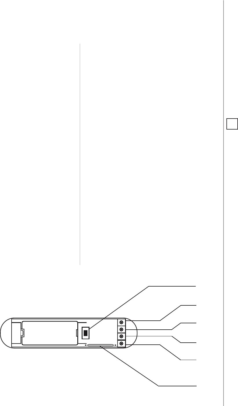
#10: Specications
TMP
- button used for including/excluding the device
and tamper detection
TP
(TEMP_POWER) - power supply terminal of
temperature sensor
TD
(TEMP_DATA) - signal terminal of temperature
sensor
GND
(GROUND) - ground terminal
IN
- potential-free input
TP (VDQ)
TD (DQ)
GND
IN
TMP
(TOP VIEW)
MAGNETIC
SENSOR
+
-
NOTE
Radio frequency of
individual device
must be same as your
Z-Wave controller.
Check information
on the box or consult
your dealer if you are
not sure.
i

20
REGULATIONS
#11: Regulations
This device complies with Part 15 of the FCC Rules
Operation is subject to the following two conditions:
1. This device may not cause harmful interference
2. This device must accept any interference received, including interfe-
rence that may cause undesired operation. This equipment has been
tested and found to comply with the limits for a Class B digital device,
pursuant to part 15 of the FCC Rules. These limits are designed to pro-
vide reasonable protection against harmful interference in a residen-
tial installation. This equipment generates, uses and can radiate radio
frequency energy and, if not installed and used in accordance with the
instructions, may cause harmful interference to radio communications.
However, there is no guarantee that interference will not occur in a par-
ticular installation. If this equipment does cause harmful interference
to radio or television reception, which can be determined by turning
the equipment o and on, the user is encouraged to try to correct the
interference by one or more of the following measures:
• Reorient or relocate the receiving antenna.
• Increase the separation between the equipment and receiver.
• Connect the equipment into an outlet on a circuit dierent from
that to which the receiver is connected.
• Consult the dealer or an experienced radio/TV technician for help.
Industry Canada (IC) Compliance Notice
This device complies with Industry Canada license-exempt RSSs. Ope-
ration is subject to the following two conditions: (1) this device may
not cause interference, and (2) this device must accept any interferen-
ce, including interference that may cause undesired operation of the
device.
Cet appareil est conforme aux normes d’exemption de licence RSS d’In-
dustry Canada. Son fonctionnement est soumis aux deux conditions
suivantes : (1) cet appareil ne doit pas causer d’interférence et (2) cet
appareil doit accepter toute interférence, notamment les interférences
qui peuvent aecter son fonctionnement.
Legal Notices
All information, including, but not limited to, information regarding the
features, functionality, and/or other product specication are subject
to change without notice. Fibaro reserves all rights to revise or upda-
te its products, software, or documentation without any obligation to
notify any individual or entity.
FIBARO and Fibar Group logo are trademarks of Fibar Group S.A. All
other brands and product names referred to herein are trademarks of
their respective holders.

21
REGULATIONS
Note
Changes and modications not expressly approved by the manufactu-
rer or registrant of this equipment can void your authority to operate
this equipment under Federal Communications Commission’s rules.
DGT Warning Statement
Article 12
Without permission, any company, rm or user shall not alter the frequ-
ency, increase the power, or change the characteristics and functions
of the original design of the certied lower power frequency electric
machinery.
Article 14
The application of low power frequency electric machineries shall not
aect the navigation safety nor interfere a legal communication, if an
interference is found, the service will be suspended until improvement
is made and the interference no longer exists.
第十二條
經型式認證合格之低功率射頻電機,非經許可,公司、商號或使用
者均不得擅自變更頻率、加大功率或變更原設計之特性及功能。
第十四條
低功率射頻電機之使用不得影響飛航安全及干擾合法通信;經發現
有干擾現象時,應立即停用,並改善至無干擾時方得繼續使用。
前項合法通信,指依電信法規定作業之無線電通信。
低功率射頻電機須忍受合法通信或工業、科學及醫療用電波輻射性
電機設備之干擾。
Declaration of conformity
Hereby, Fibar Group S.A. declares that FIBARO Door/Window Sensor
is in compliance with the essential requirements and other relevant
provisions of Directive 2014/53/EU.