Fibar Group FGS223 Fibaro Double Switch 2 User Manual FGS 2x3 User Guide
Fibar Group S.A. Fibaro Double Switch 2 FGS 2x3 User Guide
UserManual.wiki
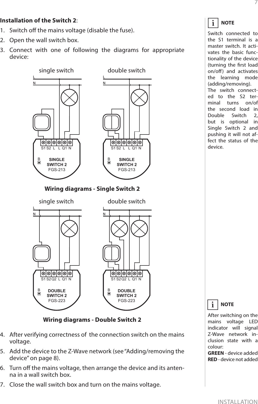
>
Fibar Group
>
FGS223 User Manual
FGS-2x3 User Guide
Navigation menu
Upload a User Manual
Namespaces
Wiki Guide
HTML
PDF
Info
Views
User Manual
Discussion / Help
Navigation
![12POWER AND ENERGY CONSUMPTION#6: Power and energy consumptionThe Switch 2 allows for the active power and energy consump-tion monitoring. Data is sent to the main Z-Wave controller, e.g. Home Center. Measuring is carried out by the most advanced micro-controller tech-nology, assuring maximum accuracy and precision (+/- 1% for loads greater than 5W).Electric active power - power that energy receiver is changing into a work or a heat. The unit of active power is Watt [W].Electric energy - energy consumed by a device through a time period. Consumers of electricity in households are billed by sup-pliers on the basis of active power used in given unit of time. Most commonly measured in kilowatt-hour [kWh]. One kilowatt-hour is equal to one kilowatt of power consumed over period of one hour, 1kWh = 1000Wh.CAUTIONThe Switch 2 require the power consump-tion of connected load equal to 5W or greater to correctly measure the power and energy. !CAUTIONThe Switch 2 stores periodically (every hour) the consump-tion data in the device memory. Disconnect-ing the module from the power supply will not erase stored ener-gy consumption data. !Resetting consumption memory:The Switch 2 allows to erase stored consumption data in three ways: a) Using functionality of a Z-Wave controller (see the controller’s manual). b) Manually clearing the data using the following procedure: 1. Switch o the mains voltage (disable the fuse).2. Remove the Switch 2 from the wall switch box.3. Switch on the mains voltage.4. Press and hold the B-button to enter the menu.5. Wait for the visual LED indicator to glow green.6. Quickly release and click the B-button again.7. Energy consumption memory will be erased.c) By resetting the device (see “Operating the device” on page 9).NOTEPower measurement can contain mains voltage uctuations within +/- 10%.i](https://usermanual.wiki/Fibar-Group/FGS223/User-Guide-3067183-Page-12.png)
![16ADVANCED PARAMETERSThe Switch 2 allows to customize its operation to user’s needs. The settings are available in the FIBARO interface as simple options that may be chosen by selecting the appropriate box.In order to congure the Switch 2 (using the Home Center controller):1. Go to the device options by clicking the icon: 2. Select the „Advanced” tab.#10: Advanced parameters9. Restore state after power failureThis parameter determines if the device will return to state prior to the power failure after power is restored.Available settings: 0 - the device does not save the state prior to the power failure and returns to „o” position 1 - the device restores its state prior to the pow-er failureDefault setting: 1Parameter size: 1 [byte]10. First channel - operating modeThis parameter allows to choose operating for the 1st channel con-trolled by the S1 switch. Available settings: 0 - standard operation1 - delay ON2 - delay OFF3 - auto ON4 - auto OFF5 - ashing modeDefault setting: 0Parameter size: 1 [byte]11. First channel - reaction to switch for delay/auto ON/OFF modesThis parameter determines how the device in timed mode reacts to pushing the switch connected to the S1 terminal.Available settings: 0 - cancel mode and set target state1 - no reaction to switch - mode runs until it ends2 - reset timer - start counting from the beginningDefault setting: 0Parameter size: 1 [byte]](https://usermanual.wiki/Fibar-Group/FGS223/User-Guide-3067183-Page-16.png)
![17ADVANCED PARAMETERS12. First channel - time parameter for delay/auto ON/OFF modesThis parameter allows to set time parameter used in timed modes. Available settings: 0 (0.1s), 1-32000 (1-32000s, 1s step) - time parameterDefault setting: 50 (50s) Parameter size: 2 [bytes]13. First channel - pulse time for ashing modeThis parameter allows to set time of switching to opposite state in ashing mode.Available settings: 1-32000 (0.1-3200.0s, 0.1s step) - time param-eterDefault setting: 5 (0.5s) Parameter size: 2 [bytes]15. Second channel - operating mode (FGS-223 only)This parameter allows to choose operating for the 1st channel con-trolled by the S2 switch. Available settings: 0 - standard operation1 - delay ON2 - delay OFF3 - auto ON4 - auto OFF5 - ashing modeDefault setting: 0Parameter size: 1 [byte]16. Second channel - reaction to switch for delay/auto ON/OFF modes (FGS-223 only)This parameter determines how the device in timed mode reacts to pushing the switch connected to the S2 terminal.Available settings: 0 - cancel mode and set target state1 - no reaction to switch - mode runs until it ends2 - reset timer - start counting from the beginningDefault setting: 0Parameter size: 1 [byte]17. Second channel - time parameter for delay/auto ON/OFF modes (FGS-223 only)This parameter allows to set time parameter used in timed modes. Available settings: 0 (0.1s), 1-32000 (1-32000s, 1s step) - time parameterDefault setting: 50 (50s) Parameter size: 2 [bytes]](https://usermanual.wiki/Fibar-Group/FGS223/User-Guide-3067183-Page-17.png)
![18ADVANCED PARAMETERS18. Second channel - pulse time for ashing mode (only FGS-223)This parameter allows to set time of switching to opposite state in ashing mode.Available settings: 1-32000 (0.1-3200.0s, 0.1s step) - time param-eterDefault setting: 5 (0.5s) Parameter size: 2 [bytes]20. Switch type This parameter denes as what type the device should treat the switch connected to the S1 and S2 terminals. Available settings: 0 - momentary switch 1 - toggle switch (contact closed - ON, contact opened - OFF) 2 - toggle switch (device changes status when switch changes status)Default setting: 2Parameter size: 1 [byte]21. Flashing mode - reportsThis parameter allows to dene if the device sends reports during the ashing mode.Available settings: 0 - the device does not send reports1 - the device sends reportsDefault setting: 0Parameter size: 1 [byte]27. Associations in Z-Wave network security modeThis parameter denes how commands are sent in specied asso-ciation groups: as secure or non-secure. Parameter is active only in Z-Wave network security mode. This parameter does not apply to 1st „Lifeline” group.Available settings: 1 - 2nd group sent as secure2 - 3rd group sent as secure4 - 4th group sent as secure8 - 5th group sent as secureDefault setting: 15 (all) Parameter size: 1 [byte]28. S1 switch - scenes sentThis parameter determines which actions result in sending scene IDs assigned to them.Available settings: 1 - Key pressed 1 time2 - Key pressed 2 times4 - Key pressed 3 times8 - Key Hold Down and Key ReleasedDefault setting: 0Parameter size: 1 [byte]NOTEParameter 27 values may be combined, e.g. 1+2=3 means that 2nd & 3rd groups are sent as secure.iNOTEParameter 28 values may be combined, e.g. 1+2=3 means that scenes for single and double click are sent.i](https://usermanual.wiki/Fibar-Group/FGS223/User-Guide-3067183-Page-18.png)
![19ADVANCED PARAMETERS29. S2 switch - scenes sentThis parameter determines which actions result in sending scene IDs assigned to them.Available settings: 1 - Key pressed 1 time2 - Key pressed 2 times4 - Key pressed 3 times8 - Key Hold Down and Key ReleasedDefault setting: 0Parameter size: 1 [byte]30. S1 switch - associations sent to 2nd and 3rd association groupsThis parameter determines which actions are ignored when sending commands to devices associated in 2nd and 3rd association group. All actions are active by default.Available settings: 1 - ignore turning ON with 1 click of the switch2 - ignore turning OFF with 1 click of the switch4 - ignore holding and releasing the switch*8 - ignore double click of the switch**Default setting: 0Parameter size: 1 [byte]31. S1 switch - Switch ON value sent to 2nd and 3rd association groupsThis parameter denes value sent with Switch ON command to devic-es associated in 2nd and 3rd association group. Available settings: 0-255 - sent valueDefault setting: 255 Parameter size: 2 [bytes]32. S1 switch - Switch OFF value sent to 2nd and 3rd association groupsThis parameter denes value sent with Switch OFF command to de-vices associated in 2nd and 3rd association group. Available settings: 0-255 - sent valueDefault setting: 0Parameter size: 2 [bytes]33. S1 switch - Double Click value sent to 2nd and 3rd association groupsThis parameter denes value sent with Double Click command to de-vices associated in 2nd and 3rd association group. Available settings: 0-255 - sent valueDefault setting: 99 Parameter size: 2 [bytes]NOTESetting parameters 31-33, 36-38 to appro-priate value should re-sult in:0 - turning o associ-ated devices1-99 - forcing level of associated devices255 - setting associat-ed devices to the last remembered state or turning them oniNOTEParameter 29 values may be combined, e.g. 1+2=3 means that scenes for single and double click are sent.iNOTEParameter 30 values may be combined, e.g. 1+2=3 means that as-sociations for turning ON and OFF are not sent.iNOTE*Hold and release is inactive when param-eter 20 is set to 1 or 2.**Double click is inac-tive when parameter 20 is set to 1.i](https://usermanual.wiki/Fibar-Group/FGS223/User-Guide-3067183-Page-19.png)
![20ADVANCED PARAMETERS35. S2 switch - associations sent to 4th and 5th association groupsThis parameter determines which actions result in sending com-mands to devices associated in 4th and 5th association group. All actions are active by default.Available settings: 1 - ignore turning on with 1 click of the switch2 - ignore turning o with 1 click of the switch4 - ignore holding and releasing the switch*8 - ignore double click of the switch**Default setting: 0Parameter size: 1 [byte]36. S2 switch - Switch ON value sent to 4th and 5th association groupsThis parameter denes value sent with Switch ON command to devic-es associated in 4th and 5th association group. Available settings: 0-255 - sent valueDefault setting: 255 Parameter size: 2 [bytes]37. S2 switch - Switch OFF value sent to 4th and 5th association groupsThis parameter denes value sent with Switch OFF command to de-vices associated in 4th and 5th association group. Available settings: 0-255 - sent valueDefault setting: 0Parameter size: 2 [bytes]38. S2 switch - Double Click value sent to 4th and 5th association groupsThis parameter denes value sent with Double Click command to de-vices associated in 4th and 5th association group. Available settings: 0-255 - sent valueDefault setting: 99 Parameter size: 2 [bytes]40. Reaction to General AlarmThis parameter determines how the device will react to General Alarm frame. Available settings: 0 - alarm frame is ignored1 - turn ON after receiving the alarm frame2 - turn OFF after receiving the alarm frame3 - ash after receiving the alarm frameDefault setting: 3Parameter size: 1 [byte]NOTEParameter 35 values may be combined, e.g. 1+2=3 means that as-sociations for turning ON and OFF are not sent.iNOTE*Hold and release is inactive when param-eter 20 is set to 1 or 2.**Double click is inac-tive when parameter 20 is set to 1.i](https://usermanual.wiki/Fibar-Group/FGS223/User-Guide-3067183-Page-20.png)
![21ADVANCED PARAMETERS41. Reaction to Flood AlarmThis parameter determines how the device will react to Flood Alarm frame. Available settings: 0 - alarm frame is ignored1 - turn ON after receiving the alarm frame2 - turn OFF after receiving the alarm frame3 - ash after receiving the alarm frameDefault setting: 2Parameter size: 1 [byte]42. Reaction to CO/CO2/Smoke AlarmThis parameter determines how the device will react to CO, CO2 or Smoke frame. Available settings: 0 - alarm frame is ignored1 - turn ON after receiving the alarm frame2 - turn OFF after receiving the alarm frame3 - ash after receiving the alarm frameDefault setting: 3Parameter size: 1 [byte]43. Reaction to Heat AlarmThis parameter determines how the device will react to Heat Alarm frame. Available settings: 0 - alarm frame is ignored1 - turn ON after receiving the alarm frame2 - turn OFF after receiving the alarm frame3 - ash after receiving the alarm frameDefault setting: 1Parameter size: 1 [byte]44. Flashing alarm durationThis parameter allows to set duration of ashing alarm mode. Available settings: 1-32000 (1-32000s, 1s step) - durationDefault setting: 600 (10min) Parameter size: 2 [bytes]50. First channel - power reportsThis parameter determines the minimum change in consumed power that will result in sending new power report to the main controller.Available settings: 0 - reports are disabled1-100 (1-100%) - change in powerDefault setting: 20 (20%) Parameter size: 1 [byte]](https://usermanual.wiki/Fibar-Group/FGS223/User-Guide-3067183-Page-21.png)
![22ADVANCED PARAMETERS51. First channel - minimal time between power reportsThis parameter determines minimum time that has to elapse before sending new power report to the main controller.Available settings: 0 - reports are disabled1-120 (1-120s) - report intervalDefault setting: 10 (10s) Parameter size: 1 [byte]53. First channel - energy reportsThis parameter determines the minimum change in consumed ener-gy that will result in sending new energy report to the main controller.Available settings: 0 - reports are disabled1-32000 (1-32000Wh) - change in energyDefault setting: 100 (100Wh)Parameter size: 2 [bytes]54. Second channel - power reports (FGS-223 only)This parameter determines the minimum change in consumed power that will result in sending new power report to the main controller.Available settings: 0 - reports are disabled1-100 (1-100%) - change in powerDefault setting: 20 (20%) Parameter size: 1 [byte]55. Second channel - minimal time between power reports (FGS-223 only)This parameter determines minimum time that has to elapse before sending new power report to the main controller.Available settings: 0 - periodic reports are disabled1-120 (1-120s) - report intervalDefault setting: 10 (10s) Parameter size: 1 [byte]57. Second channel - energy reports (FGS-223 only)This parameter determines the minimum change in consumed ener-gy that will result in sending new energy report to the main controller.Available settings: 0 - reports are disabled1-32000 (1-32000Wh) - change in energyDefault setting: 100 (100Wh)Parameter size: 2 [bytes]58. Periodic power reportsThis parameter determines in what time interval the periodic power reports are sent to the main controller.Available settings: 0 - periodic reports are disabled1-32000 (1-32000s) - report intervalDefault setting: 3600 (1h) Parameter size: 2 [bytes]](https://usermanual.wiki/Fibar-Group/FGS223/User-Guide-3067183-Page-22.png)
![23ADVANCED PARAMETERS59. Periodic energy reportsThis parameter determines in what time interval the periodic energy reports are sent to the main controller.Available settings: 0 - periodic reports are disabled1-32000 (1-32000s) - report intervalDefault setting: 3600 (1h) Parameter size: 2 [bytes]60. Measuring energy consumed by the device itselfThis parameter determines whether energy metering should include the amount of energy consumed by the device itself. Results are be-ing added to energy reports for rst endpoint.Available settings: 0 - function inactive1 - function activeDefault setting: 0Parameter size: 1 [byte]](https://usermanual.wiki/Fibar-Group/FGS223/User-Guide-3067183-Page-23.png)