Fiber Span FS31X-4 FIBER OPTIC SYSTEM/ REPEATER User Manual Fiber Span FS31 Series Manual
Fiber-Span LLC FIBER OPTIC SYSTEM/ REPEATER Fiber Span FS31 Series Manual
users manual

Page 1 of 13 Rev 01 5-DEC-06 Fiber Optic RF Repeater System
Fiber-Span
Fiber Optic RF Repeater System
FS31 Series User Manual

Page 2 of 13 Rev 01 5-DEC-06 Fiber Optic RF Repeater System
Fiber-Span ..........................................................................................................................1
Fiber Optic RF Repeater System ......................................................................................1
FS31 Series User Manual....................................................................................................1
1 Introduction ...................................................................................................................2
2 Warnings.......................................................................................................................2
Warning: Invisible radiation exits from areas labeled “Aperture”.........................................2
3 Product Overview..........................................................................................................3
4 Product Diagrams .........................................................................................................4
5 RF Path Definitions.......................................................................................................6
6 Installation Guide ..........................................................................................................6
6.1 General..................................................................................................................6
6.2 Fiber Transceiver Unit (FTU) .................................................................................6
6.3 Remote Repeater Unit (RRU) and Integrated Head-end Unit (IHU) ......................7
6.4 Caution ................................................................................................................12
7 Maintenance ...............................................................................................................12
8 Company Information..................................................................................................12
9 Reference Documents ................................................................................................13
1 Introduction
This manual outlines the operation and setup for Fiber-Span Fiber Optic Based RF
Repeaters.
2 Warnings
Figure 1. Laser Warning Label
Warning: Invisible radiation exits from areas labeled “Aperture”
AC power is used to supply power up the system modules. Use precautions to
prevent electrical shock hazards. Always terminate the RF connections before
applying power to the unit.
Page 3 of 13 Rev 01 5-DEC-06 Fiber Optic RF Repeater System
3 Product Overview
Fiber-Span provides product to enable RF signal to be distributed via optical fiber
cable. RF signal sources can be used from over the air (OTA) from a Radio Base
Station (BS), OTA from handheld devices, or directly from a BS radio. RF signals
are converted to modulated light for transport through optical fiber media to remote
locations. Modulated light is converted back to the original RF signal where it is
processed through filtering and amplification to allow the RF signal to be re-radiated
in the remote location. In a bi-directional RF system, the process is the same
resulting in remote RF signals that are sent back simultaneously.
Fiber-Span product functionality
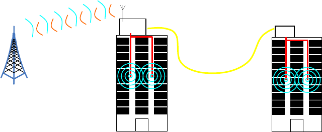
OTA system - RF signals from a remote base station are interchanged usually from
a roof top antenna that is connected to an Integrated Head-end Unit (IHU). The IHU
receives downlink signals from the base station and sends uplink signals back to the
base station. The IHU distributes signals via fiber optics to remote location and also
is capable of simultaneously interfacing with a Distributed Antenna System (DAS)
for short range RF distribution.
Figure 2. Typical OTA Optical RF distribution System
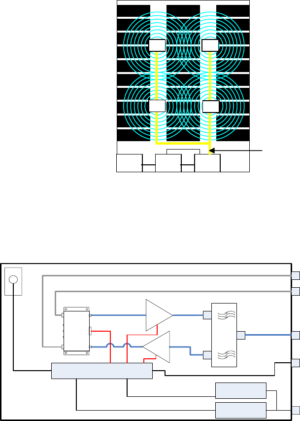
Local Base Station System – Signals from a local base station interface to optical
distribution equipment through Base Station Units (BSU), or directly to a Fiber
Transceiver Unit (FTU). The BSU sometimes interfaces the Base Station to the
FTU. The BSU is used to passively condition RF levels or serve as RF filters when
applicable. The FTU performs bi-directional optical-RF conversions. Optical
signals are sent to the Remote Repeater Unit (RRU). The RRU is designed for use
as a remote end of a bi-directional RF distribution system. The RRU RF port works
with a direct connected RF antenna or to a Distributed Antenna System (DAS).
The RRU is connected via optical fibers to a Fiber Transceiver Unit (FTU) to
complete a point to point RF link.
IHU RRU
Remote Base
Station
DAS in
Building DAS in
Building
Optical
Fiber
Page 4 of 13 Rev 01 5-DEC-06 Fiber Optic RF Repeater System
Figure 3. Local Base Station System
4 Product Diagrams
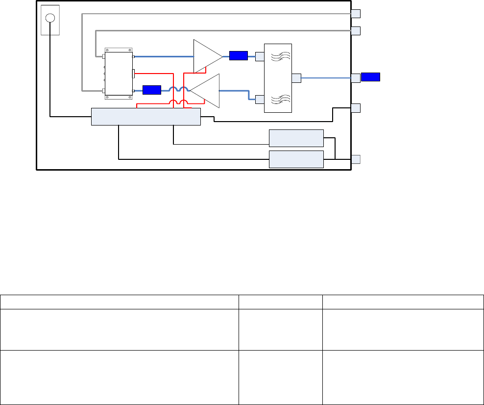
RRU Block Diagram
Line
Cord
PA
PA
L
L
C
C
H
H
Power
Supply +28V
N-F
Fiber
Transceiver
FC/APC
FC/APC
[Alarm]
[RF]
[Opt Out]
[Opt In]
Control Board
Power
Supply +12V
LNA
LNA
Door
Switch
Figure 4. Simplified Block Diagram of RRU
Optical
Fiber
BTS BSU FTU
RRU
RRU
RRU RRU
Page 5 of 13 Rev 01 5-DEC-06 Fiber Optic RF Repeater System
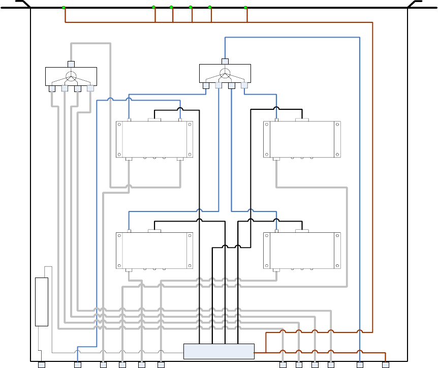
FTU Block Diagram
Power Supply
Control PCB
AC Power
Entry
Optical In (4)
FC/APC Optical Out (4)
FC/APC
[RF In] [RF Out]
Fiber Optic
Transceiver Fiber Optic
Receiver
Optical 4-Way
4-Way RF Combiner
N-RF
[Opt In 1]
[Opt In 2]
[Opt In 3]
[Opt In 4]
[Opt Out 3]
[Opt Out 2]
[Opt Out 4]
[Opt Out 1]
[Power]
[Laser Alarm]
[Receiver 1 Alarm]
[Receiver 2 Alarm]
[Receiver 3 Alarm]
[Receiver 4 Alarm]
N-RF
[Gain 3]
[Opt In Alm 3]
[Gain 4]
[Opt In Alm 4]
[Gain 1]
[Opt In Alm 1]
[Gain 2]
[Opt In Alm 2]
[Laser Alm 1]
[Summary Alarms]
Fiber Optic
Receiver
Fiber Optic
Receiver
Optional
Figure 5. FTU Block Diagram (4-Way FTU Shown)
Page 6 of 13 Rev 01 5-DEC-06 Fiber Optic RF Repeater System
5 RF Path Definitions
The RF paths are defined as follows:
Downlink – Originates at the FTU or and IHU, over fiber to the RRU to the RF Port.
The Downlink generally is defined by the RF output power the RRU can deliver.
Uplink – Originates at the RRU, over the fiber to the FTU or IHU to the RF Out Port.
The Uplink is generally defined by RF input sensitivity.
6 Installation Guide
6.1 General
All unused RF Terminals must be terminated with a 50 Ohm load. All unused Optical
Terminals must be protected using dust cover cap. When installing fiber optic cables,
remove dust covers, clean optical connector with optical grade alcohol, align FC/APC
connector KEY and hand tighten. Do not over tighten. Keep fiber bend radiuses
greater than 1.5 inches.
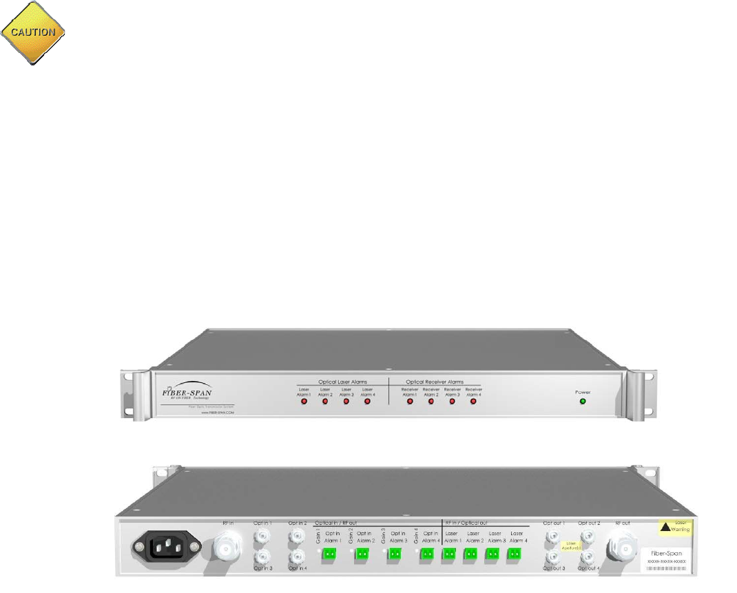
6.2 Fiber Transceiver Unit (FTU)
The Fiber Transceiver Unit (FTU) is a 19” standard 1U sub-rack. The FTU requires
AC Power (90 to 220 VAC, 50-60 Hz). The AC interface is a standard IEC Power
socket. A US 120V AC Line Cord is supplied with each FTU.
Mount Fiber Transceiver Unit away from excessive heat sources. Make all RF
connections and terminate all unused RF connections before applying AC Power.
User interface information can be found in attached outline drawing.
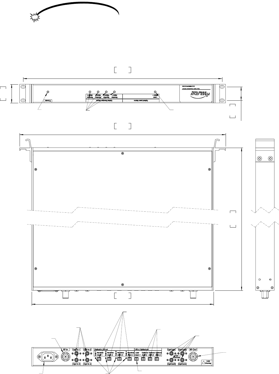
Figure 6. FTU Front View
Figure 7. FTU Rear View

Page 7 of 13 Rev 01 5-DEC-06 Fiber Optic RF Repeater System
Alarms
The Opt in Alarm interface uses a wire contact header (supplied) that will plug into
the Opt in Alarm sockets. Connection of alarm wires to the wire contact header
requires a small standard flathead screwdriver. The connections are dry contact relay
terminals. The alarm LED’s on the front panel indicate alarm conditions for each
individual uplink optical receiver and downlink optical transmitter. An optional
Summary alarm is available.
A receiver alarm is triggered by excessive optical loss. The transmitter alarm is
triggered when the laser transmitter runs over bias. Normal operation leaves the
contacts normally open (NO). In the event of an alarm condition, the corresponding
contacts close.
RF Levels
For the uplink, each receiver has a gain control that is accessed using a small
standard screwdriver on the FTU rear.
For Uplink, disconnect the downlink optical fiber on the FTU side to ensure that there
is no RF output at the RRU RF port. Turn down the gain on ALL FTU receivers (if
FTU is more than a 1-Way) using gain control by turning CCW at least 12 turns. On
the RRU side, connect a RF tone generator set to an RF level of -50 dBm at the
center of the uplink frequency. On the FTU, set RF output to the desired level at the
FTU RF output by adjusting corresponding FTU receiver gain control. Repeat for
other Uplinks individually if applicable and leave gain settings of previous calibrated
uplinks unchanged. The goal is to balance the uplink gains to be all equal.
For downlink, provide composite RF level into FTU transceiver at 0 dBm.
All unused RF Terminals must be terminated with a 50 Ohm load. All unused Optical
Terminals must be protected using dust cover cap. When installing fiber optic cables,
remove dust covers, clean optical connector with optical grade alcohol, align FC/APC
connector KEY and hand tighten. Do not over tighten. Keep fiber bend radiuses
greater than 1.5 inches.
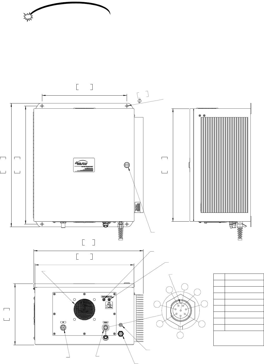
6.3 Remote Repeater Unit (RRU) and Integrated Head-end Unit (IHU)
The RRU/IHU requires AC Power (90 to 220 VAC, 50-60 Hz). Connect RRU to earth
ground using Earth Ground Lug on the external side of RRU. If the unit is a wall
mount type, use the dimensional information provided with the Outline Drawing
(example attached). Mount on a sturdy location keeping clear vent holes and heat-
sink. If the unit is a rack mount type, mount the unit to allow air passage from front to
back. Space the units to allow convection air flow. If the unit is mounted inside a
larger enclosure, air ventilation must be used to keep the RRU in proper temperature
Page 8 of 13 Rev 01 5-DEC-06 Fiber Optic RF Repeater System
range. Make all RF connections and terminate all unused RF connections before
applying AC Power.
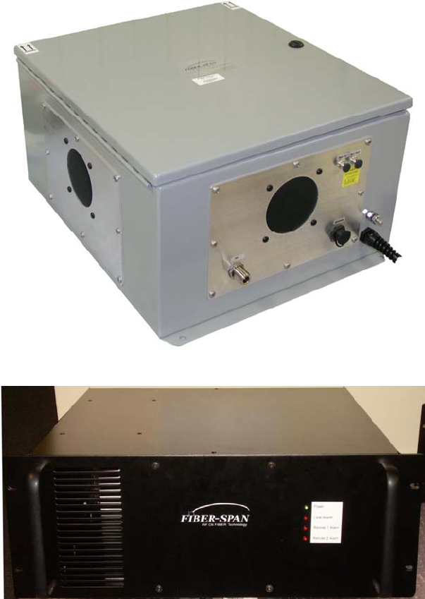
Figure 8. RRU/IHU (Wall Mount Version) Bottom Side
Figure 9. RRU/IHU (Rack Mount Version)
Alarms
The alarm interface uses a circular connector. The connections are dry contact relay
terminals. The alarm LED’s on the Control Board indicate the alarm conditions for
each individual parameter as:
Downlink Optical Receiver
Uplink Optical Transmitter
PA Alarm
Door Alarm (Wall Mount) / Fan Alarm (Rack Mount)
Page 9 of 13 Rev 01 5-DEC-06 Fiber Optic RF Repeater System
See LED alarm indicator locations in Figure 10.
A receiver alarm is triggered by excessive optical loss. The transmitter alarm is
triggered when the laser transmitter runs over bias. The PA alarm indicates that the
PA is overdriven. The Door / Fan alarm indicates when the door is left open or if a
cooling fan fails. The alarm output is summarized which makes one set of contacts
available on the circular alarm connector. Normal operation leaves the contacts
normally open (NO). In the event of an alarm condition, the corresponding contacts
close.
RF Levels
The Downlink Output level is factory set to meet the RF maximum output level that is
compatible with FCC requirements. The uplink Gain level is factory set to optimize
noise levels for the optical system. RF output levels and gain levels are adjustable
using in-line RF pads. The important In-Line Pad Locations are:
Line
Cord
PA
PA
L
L
C
C
H
H
Power
Supply +28V
N-F
Fiber
Transceiver
FC/APC
FC/APC
[Alarm]
[RF]
[Opt Out]
[Opt In]
Control Board
Power
Supply +12V
LNA
LNA
Door
Switch
A
C
B
Figure 10. RF pad locations for RRU
Pad location
A – Used to lower Downlink RF power without affecting the uplink parameters
B – Used to lower Uplink RF level into the optical transmitter without affecting
Downlink parameters
C – Used to lower Uplink and Downlink levels simultaneously
Parameter to be controlled Attenuator Comments
Lower Downlink RF Output Power Pad A SMA-
Female to
SMA-Male
Power Handling Wattage
indicated in Table 2.
Lower Uplink RF into Optical Transceiver Pad B SMA-
Female to
SMA-Male
Lowers Uplink Sensitivity,
Maximum Composite RF
input to Transceiver is 5
dBm, input P1 = 17 dBm.

Page 10 of 13 Rev 01 5-DEC-06 Fiber Optic RF Repeater System
Maximum Composite RF
into LNA (No Damage) +10
dBm, input P1 = -6 dBm,
LNA gain is 27 dB
Lower Both Uplink and Downlink Pad C N-
Female to N-
Male
External in-line attenuator
Table 1. Attenuator Configurations
IHU RF Levels
The IHU downlink has a high gain to boost weak received signals to levels to drive
the optical components. Do not allow a composite RF level greater than 0 dBm into
the optical transceiver. See the IHU rear RF INPUT MAX information. Uplink power
settings can be done as the RRU instructions.
RRU RF power Considerations
The RRU is available with many RF power outputs. For each product, there are
considerations for pad power dissipation. Product power levels are the Output P1 dB
compression point.
Model Series Minimum Attenuator Dissipation
FS31RX-A, ½ Watt 1 Watt
FS31RX-B, 1 Watt 2 Watts
FS31RX-C, 5 Watt 10 Watts
FS31RX-D, 10 Watt 20 Watts
FS31RX-E, 20 Watt 50 Watts
Table 2. Attenuator Power Dissipation Recommendations For Attenuator A or D
RRU Photographs
Page 11 of 13 Rev 01 5-DEC-06 Fiber Optic RF Repeater System
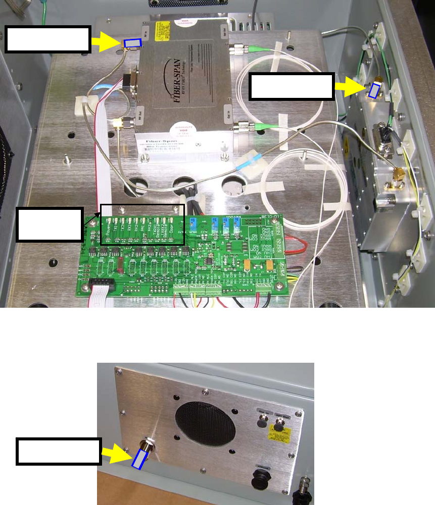
Figure 11. RRU Attenuator Locations Pad A and Pad B (SMA-Female to SMA-Male)
Figure 12. RRU Attenuator Location for Pad C (N-Female to N-Male)
Attenuator A
Attenuator B
Attenuator C
LED Alarm
Indicators

Page 12 of 13 Rev 01 5-DEC-06 Fiber Optic RF Repeater System
6.3.1 Recommended System Start up Procedure
• Verify all RF cables are connected and all unused RF connections terminated with
50 Ohm terminations.
• Verify all Alarm and AC connections are properly made
• Connect fiber optic cables.
• Apply AC power to system components.
6.4 Caution
RRU has internal AC power connections that can cause shock if operator is not
careful. Always verify the AC Power area is clear of all objects. Do not leave
objects inside the RRU that can cause dangerous shock hazard.
7 Maintenance
This Fiber Optic repeater system does not require scheduled maintenance.
However, use precautions while installing optical fibers to keep connector surfaces
clean. An unclean optical connector surface can damage the internal transceiver
connector which can degrade system performance and violate Fiber-Span warranty.
Keep heat dissipating surfaces or vents clean and clear.
8 Company Information
Fiber-Span designs and manufactures fiber optic modules and systems used in the
transmission and distribution of RF and wireless signals. Fiber-Span’s fiber optic
transmitters, receivers and transceivers are widely used in wireless and RF systems
worldwide by wireless systems OEM’s, systems integrators and military systems
designers to capitalize on the inherent advantages of fiber. Fiber has extremely low
RF attenuation (< 1dB/km), very high bandwidth, immunity to EMI, no signal egress,
flat broadband delay characteristics plus a cable design that is light weight and
small size.
Fiber-Span
111 Corporate Blvd.
South Plainfield, NJ 07080
USA
908-754-0646
908-754-0647 FAX
Internet
http://www.fiber-span.com
techinfo@fiber-span.com
Page 13 of 13 Rev 01 5-DEC-06 Fiber Optic RF Repeater System
9 Reference Documents
Example Document Title Example Document Description
FS31FS-04-LM-OUT 4-Way FTU Transceiver
FS31RS-90-C-06-WM-OUT RRU Transceiver, SMR-900, 5W
FS31X-1.9-60-2-RM-OUT IHU Transceiver, PCS, 5W
Units:
www.fiber-span.com
Dwg. No. FS31FS-04-LM-OUT Rev:1
[millimeters]
Projection
4-Way with Local Alarms, 1U Rackmount
FS31FS-04-LM, Fiber Transceiver Unit,
111 Corporate Blvd.
inches
S. Plainfield, NJ 07080
Fiber-Span Third
Angle
Outline Drawing
19.0
481.5
425.2
16.74
18.00
457.2
Laser Alarm Relay 1
Open: OK
Closed: Laser Bias Overcurrent
IEC 320-C14
RF In
N-female
Manual RX Gain
Control Pot 1-4
RF Out
N-female
Optical In 1-4
FC/APC Optical Out 1-4
FC/APC
AC Power Inlet
Received Optical Power Relays 1-4
Open: OK
Closed: Low or Zero Received Optical Power
Optional Alarms
Off: Fault
On: OK
Green LED
DC Power Optical Receiver Alarm 1-4
Red LED
On: Fault
Off: OK
Optical Laser Alarm
Red LED
On: Fault
Off: OK
31.8
18.30
464.9
1.25
1.72
43.7
FIBER-SPAN
RF ON FIBER
®
Technology
16.75
425.5
304.8
12.00
444.5
17.50
0.31 Typ.
7.9
1/4-Turn Door Latch
Pin Function
1Summary Alarm
2Summary Alarm
3 No Connect
4 No Connect
5 No Connect
6 No Connect
7 No Connect
8 No Connect
Dry Contact
Normally Open when
Status is OK
Optical Out
AC Line Cord
FC/APC
(1/4"-20 Thread)
RF port
Ground Stud
Alarms
N-female
Optical In
FC/APC
355.6
14.00
15.47
393
8.66
220
AIR VENTS - DO NOT BLOCK
(Top, Bottom, & Side of Unit)
5
6
7
Pin Locations
Location
1
2
3
4
Note Key
8
16.00
406.4
www.fiber-span.com
Projection
Dwg. No. FS31RS-90-C-06-WM-OUT Rev:1
S. Plainfield, NJ 07080
Units:
[millimeters]
FS31RS-90-C-06-WM, Remote Repeater Unit,
111 Corporate Blvd.
inches
Wall-Mount Enclosure
Fiber-Span Third
Angle
Outline Drawing
FIBER-SPAN
RF ON FIBER
®
Technology
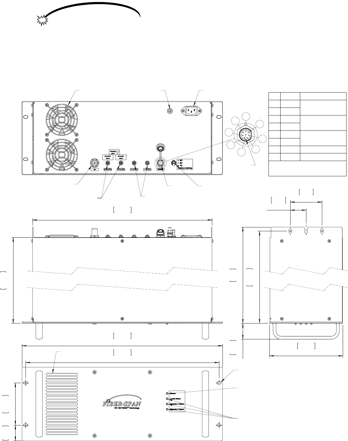
Pin Desc. Function
1N.O. Local
Summary Alarm
2Com.
3N.O. Remote 1
Summary Alarm
4Com.
5N.O. Remote 2
Summary Alarm
6Com.
7- -
8- -
Dry Contact Normally
Open when Status is OK
111 Corporate Blvd.
www.fiber-span.com
Dwg. No. FS31X-1.9-60-2-RM-OUT Rev:1
[millimeters]
Projection
4U Rackmount
FS31X-1.9-60-2-RM, IHU, 1850-1990 MHz, 5W
Units:
inches
S. Plainfield, NJ 07080
Fiber-Span Third
Angle
Outline Drawing
1.50
38.1
18.98
76.2
38.1
482
3.00
1.50
6.95
176.5
Alarms
FC/APC
Optical In 1& 2
RF
N-female
Ground Lug
1/4"-20 Thread
AC Power Entry
IEC 320
Pinout
Exhaust Fans
Do Not Block
Optical Out 1& 2
FC/APC
Remote 2 Enable Switch
7
81
2
3
4
5
6
Note Key
Location
Green LED
DC Power
Off: Fault
On: OK
Do Not Block
Air Intake
Typical
.406 x .250 Obround
Local & Remote Alarms
Red LED
On: Fault
Off: OK
465.1
18.31
482.6
19.00
4.00
101.6
1.48
37.5
17.00
431.8
18.00
457.2
18.60
472.4
FIBER-SPAN
RF ON FIBER
®
Technology