Fiber Span FS42R-1719-E CHANNELIZED BDA User Manual FS42R 1719E
Fiber-Span LLC CHANNELIZED BDA FS42R 1719E
Users Manual

Rev A Page 1 of 25
FS42R-1719E
Dual Band Fiber Fed
Outdoor Das System
Series FS42R
User Manual
RF On Fiber ®
Signal Distribution
Products for Outdoor DAS Coverage
Extension Applications

Fiber-Span
Rev A Page 2 of 25
Information in this document is subject to change without notice.
All rights reserved.
Please send comments to:
E-mail techinfo@fiber-span.com
PHONE: 908-253-9080
Fax: 908-253-9086
Revision History
Version Author Description Date Release
A J. Stewart 20-Jan-2010

Fiber-Span
Rev A Page 3 of 25
Table of Contents
1. SUMMARY...............................................................................................................................................................................5
2. GENERAL DESCRIPTION......................................................................................................................................................5
3. DUAL BAND OUTDOOR DAS REMOTE FIBER NODE (RFN) [STANDARD CONFIGURATION]..............................7
3.1 REMOTE FIBER NODE MODEL DRAWING....................................................................................................................................7
3.2 REMOTE FIBER NODE BLOCK DIAGRAM (COMMON TO ALL CONFIGURATIONS) .........................................................................7
3.3 REMOTE FIBER NODE DETAILED DESCRIPTION ..........................................................................................................................8
3.4 REMOTE FIBER NODE (RFN) EXTERNAL INTERFACES (STANDARD CONFIGURATION) ...............................................................8
3.4.1 Remote Fiber Node Interface Description .........................................................................................................................8
3.4.2 Remote Fiber Node Front Panel Drawing.........................................................................................................................9
4. DUAL BAND OUTDOOR DAS FIBER TRANSCEIVER UNIT (FTU) ................................................................................9
4.1 FIBER TRANSCEIVER UNIT MODEL DRAWING (SHOWN WITH OPTIONAL DUPLEXED INTERFACE)..............................................9
4.2 FIBER TRANSCEIVER UNIT DETAILED DESCRIPTION.................................................................................................................10
4.3 FIBER TRANSCEIVER UNIT BLOCK DIAGRAM ...........................................................................................................................11
4.4 FIBER TRANSCEIVER UNIT EXTERNAL INTERFACES (WITH OPTIONAL DUPLEXED PORTS)........................................................12
4.4.1 FTU Interface Description...............................................................................................................................................12
4.4.2 FTU Front Panel Description (show with optional Duplexed Ports) .............................................................................12
5. DUAL BAND OUTDOOR DAS SYSTEM CONNECTIONS...............................................................................................14
6. DUAL BAND OUTDOOR DAS ELECTRICAL SPECIFICATIONS...................................................................................15
7. MONITORING & CONTROL................................................................................................................................................15
8. GRAPHIC USER INTERFACE (GUI)...................................................................................................................................16
9. MECHANICAL SPECIFICATIONS ......................................................................................................................................20
10. ENVIRONMENTAL SPECIFICATIONS ..............................................................................................................................20
11. REGULATORY STATEMENTS: ..........................................................................................................................................20
12. APPENDIX A : INSTALLATION INSTRUCTIONS............................................................................................................21
Preparing for Installation................................................................................................................................................................21
Safety Precautions ...........................................................................................................................................................................21
System Installation..........................................................................................................................................................................23
Remote Fiber Node Installation.......................................................................................................................................................25
Remote Fiber Node Verification Testing..........................................................................................................................................25

Fiber-Span
Rev A Page 4 of 25
List of Figures
Figure 1: DAS System Diagram ................................................................................................................................................................5
Figure 2: Dual Band Outdoor DAS System Diagram................................................................................................................................6
Figure 3: Remote Fiber Node Model Drawing ..........................................................................................................................................7
Figure 4 Remote Fiber Node Block Diagram ............................................................................................................................................7
Figure 5: Remote Fiber Node Front Panel.................................................................................................................................................9
Figure 6: FTU Model Drawing..................................................................................................................................................................9
Figure 7: FTU Block Diagram.................................................................................................................................................................11
Figure 8: FTU Front Panel.......................................................................................................................................................................12
Figure 9: FTU Front Panel Configurations..............................................................................................................................................13
Figure 10: Dual Band Outdoor DAS System Connections......................................................................................................................14
Figure 11: Fiber-Span GUI Settings Page................................................................................................................................................17
Figure 12: GUI System Performance Display Page.................................................................................................................................18
Figure 13 – System Block Diagram.........................................................................................................................................................23
Fiber-Span
Rev A Page 5 of 25
1. Summary
This document is intended to cover the operation of the Fiber-Span Dual Band Outdoor DAS FS42R-1719E. It provides the
reader with a general description of the product and its interfaces. It contains information intended for engineers, technicians
and operators working with the Dual Band Outdoor DAS.
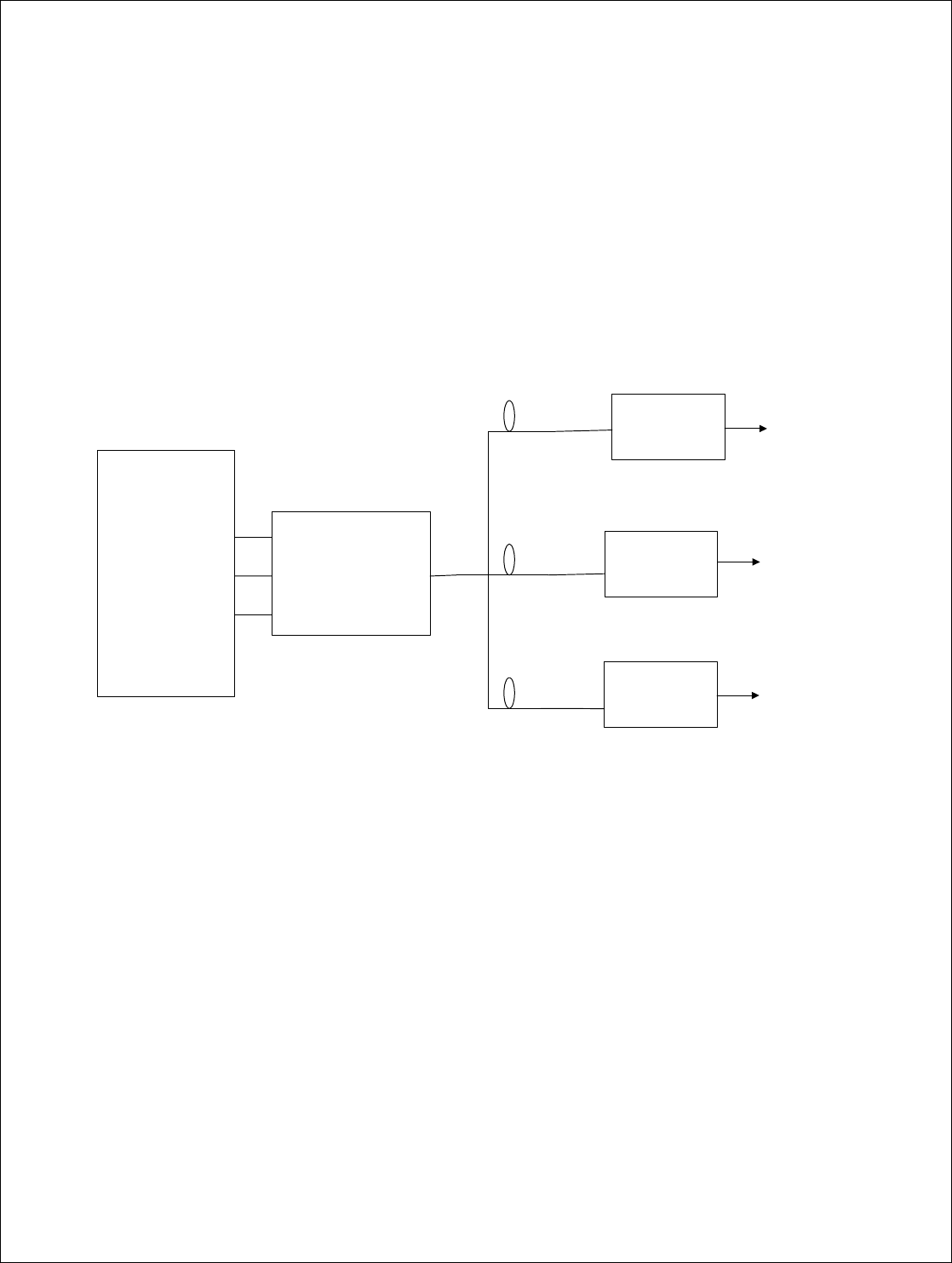
2. General Description
The Fiber-Span fiber fed Distributed Antenna System (DAS) is a wireless optical network which can be used to expand
network and capacity needs and to overcome site location constraints involving zoning issues, limited space availability or
prohibitive BTS based site lease costs . It provides connectivity between a BTS site and several Remote Antenna sites
through a fiber optic link. The DAS is made up of two main components; one FTU and three Remote Fiber Nodes. Shown
below are the FTU and the three Remote Fiber Nodes. The FTU is located near the BTS site and the Remote Fiber Node is
located at the antenna site.
HEC
REMOTE
NODE
Sector 1
REMOTE
NODE
Sector 3
REMOTE
NODE
Sector 2
To Antenna 1
To Antenna 2
To Antenna 3
Sector 1
Sector 2
Sector 3
Fiber Optic
Link 3
Fiber Optic
Link 2
Fiber Optic
Link 1
BTS
Figure 1: DAS System Diagram
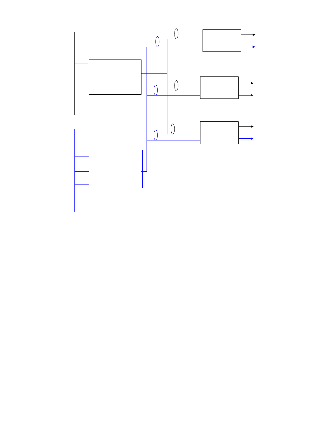
The Fiber-Span Dual Band Distributed Antenna System (DAS) FS42R-1719E is a dual band version of the Fiber-Span DAS.
It designed to work in the AWS band and the PCS band.
The Fiber-Span Dual Band Outdoor DAS is made-up of three main components:
1. Dual Band Remote Fiber Node (RFN)
2. PCS and AWS Band Fiber Transceiver Unit (FTU)
3. Element manager
FTU
Fiber-Span
Rev A Page 6 of 25
AWS HEC
REMOTE
NODE
Sector 1
REMOTE
NODE
Sector 3
REMOTE
NODE
sector 2
To AWS
Antenna
1
Fiber Optic
Link
PCS HEC
To PCS
Antenna 1
To AWS
Antenna 2
To PCS
Antenna 2
To AWS
Antenna 3
To PCS
Antenna 3
Sector 1
Sector 2
Sector 3
AWS
BTS
Sector 1
Sector 2
Sector 3
PCS
BTS
Figure 2: Dual Band Outdoor DAS System Diagram
Remote Fiber Node:
The Remote Fiber Node is dual band; it supports AWS and PCS bands.
On the UL path (RX), the Remote Fiber Node converts RF signal to optical and improves the system’s receive (Rx) noise.
floor. On the DL path (TX), the Remote Fiber Node converts optical to RF and amplifies the RF output to 20Watts (43 dBm).
Fiber Transceiver Unit:
The FTU is designed as two separate units: a PCS model and an AWS model.
On the UL path (RX), it converts optical to RF. On DL path (TX) RF to optical. The FTU also monitors and controls the
network (FTU and RFN) via the Element manager.
Element Manager: This unit can monitor and control multiple DAS Systems via the FTU’s.
AWS FTU
PCS FTU
Fiber-Span
Rev A Page 7 of 25
3. Dual Band Outdoor DAS Remote Fiber Node (RFN) [Standard
Configuration]
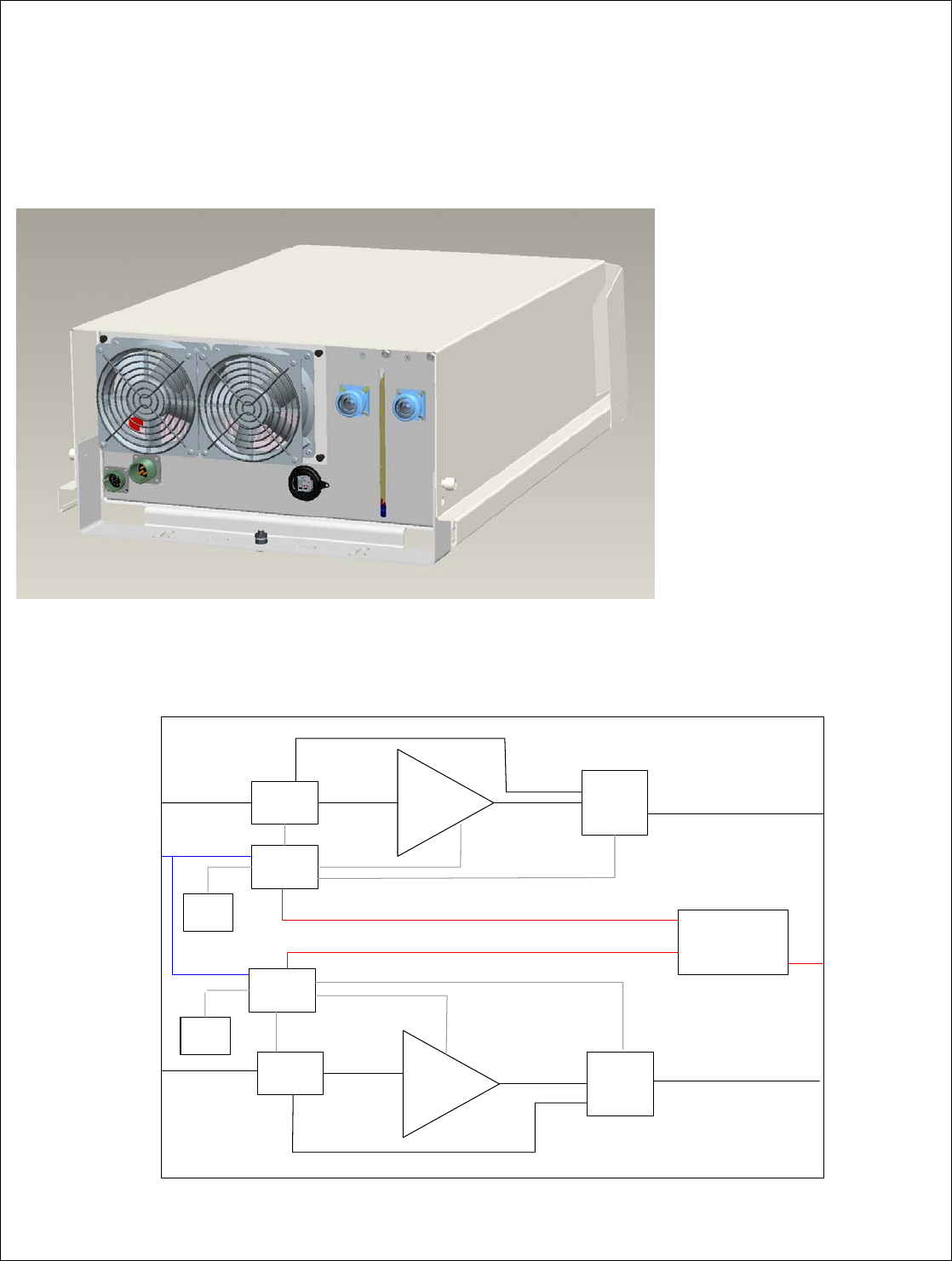
3.1 Remote Fiber Node Model Drawing
Figure 3: Remote Fiber Node Model Drawing
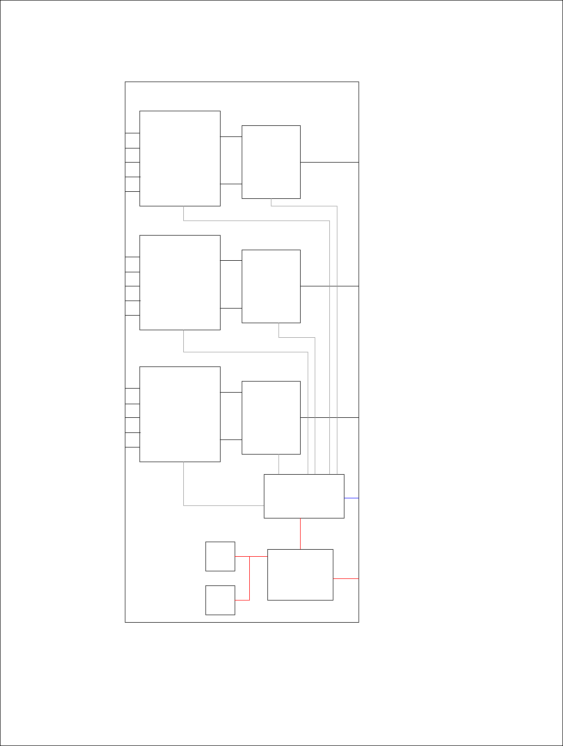
3.2 Remote Fiber Node Block Diagram (Common to all configurations)
PCS
OP/RF
Controller
PCS
MCPA PCS
DLNA
AWS
OP/RF
Controller
AWS
MCPA AWS
DLNA
POWER
SUPPLY
RX
TX
RX
TX
FAN
FAN
+28V &
CTRL +12V &
CTRL
+28V
+28V
PCS
ANTENNA
AWS
ANTENNA
FIBER
PCS
FIBER
AWS
AC 90-240V,
15A
ETHERNET -
PROPRIETARY
RS485
+28V &
CTRL +12V &
CTRL
+12V & CTRL
+12V & CTRL
Figure 4 Remote Fiber Node Block Diagram

Fiber-Span
Rev A Page 8 of 25
3.3 Remote Fiber Node Detailed Description
The Remote Fiber Node is a dual band duplexer/amplifier system. On the UL path, the Remote Fiber Node amplifies the RF
signal (low noise amplifier) and converts it to optical. On the DL path (TX), the Remote Fiber Node converts the input optical
signal to RF and amplifies the signal to 20Watts (power amplifier). Following is a brief description of each module.
OP/RF Module: Converts RF to optical and optical to RF. One is used for the PCS band and a second one is used for the
AWS band.
MCPA: Multi-carrier Power Amplfiier. The MCPA amplifies the RF output power to 20Watts (43dBm). Both MCPAs are
multicarrier, thereby insuring optimal ACP performance.
DLNA: Duplexer/Low Noise Amplifier. The DLNA duplexes the Rx and Tx signals and is designed to amplify the RX path
and improve the sysem’s noise floor.
Controller: The Controller provides power, control and monitoring to the various modules of the Remote Fiber Node. The
controller also provides communication with the unit, via a GUI based application, that can be used to display information on
the operating conditions and alarm conditions of the Remote Fiber Node.
3.4 Remote Fiber Node (RFN) External Interfaces (Standard Configuration)
3.4.1 Remote Fiber Node Interface Description
Interface Description Limits, Max.
FIBER PCS
Single Mode FC ACP
Optical Input /output Port – for PCS Band
Input from FTU on DL path
Output to FTU on UL path
PCS ANTENNA
7/16 DIN FEMALE RF Antenna Port – for PCS Band
(RF in for UL path)
(RF out for D path)
Max. input Power (UL Path): 10 dBm
Rated Output Power (DL path): 20Watts
FIBER AWS
Single Mode FC ACP
Optical Input /output Port – for AWS Band
Input from FTU on DL path
Output to FTU on UL path
AWS ANTENNA
7/16 DIN FEMALE RF Antenna Port – for AWS Band
(RF in for UL path)
(RF out for DL path)
Max. input Power (UL Path): 10 dBm
Rated Output Power (DL path): 20Watts
AC 90-250V, 15A
Power Supply Input Voltage
90 – 250 V
15 A
ETHERNET PROPRETARY
– RS485
RS485 Communication Port
For local commisioning
Fiber-Span
Rev A Page 9 of 25
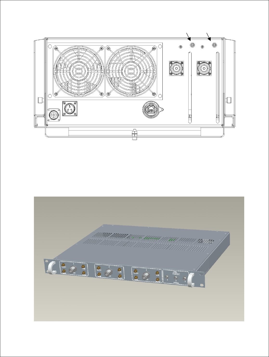
3.4.2 Remote Fiber Node Front Panel Drawing
Fiber
PCS Fiber
AWS
PCS
Antenn
a
AWS
Antenna
Ethernet
RS485
AC 90-240V,
15A
N
/A
Figure 5: Remote Fiber Node Front Panel
4. Dual Band Outdoor DAS Fiber Transceiver Unit (FTU)
4.1 Fiber Transceiver Unit Model Drawing (Shown with Optional Duplexed Interface)
Figure 6: FTU Model Drawing

Fiber-Span
Rev A Page 10 of 25
4.2 Fiber Transceiver Unit Detailed Description
The Fiber Transceiver Unit (FTU) has two different functions: it converts the input optical signal to RF on the UL path (Rx),
converts the RF input signal to optical on the DL path (Tx) and it also monitors and controls the network (FTU and RFN) via the
Element manager.
The FTU has two different input configurations:
• Separate Tx & Rx: For low power compact base station with separate Rx and Tx signals, input power –5dBm to 5dBm.
• Optional Diplexed Tx/Rx: For Tx/Rx diplexed signal from base station, input power 0- 43dBm. In this configuration, the
FTU attenuates the RF input to a suitable level for the fiber optic link (0dBm) on the DL path (Tx).
Following is the block diagram of the FTU and a brief description of each module.
OP/RF Module: Converts RF to optical and optical to RF.
RF Board: On the BTS port, duplexes the Rx and Tx signals and attenuates the RF input signal to 0dBm. On the RX separate
path (Rx out), it sets the gain of the Rx path. On the TX separate path ( Tx in), it sets the gain of the Tx path.
Controller: The Controller provides power, control and monitoring to RF Board and OP/RF modules. The controller also
provides communication with the unit via a GUI based application that can be used to display FTU information. The
controller also provides communication with the Remote Fiber Node via the fiber optic link. Communication to the controller
is established by an RS485 local Ethernet port.
Fiber-Span
Rev A Page 11 of 25
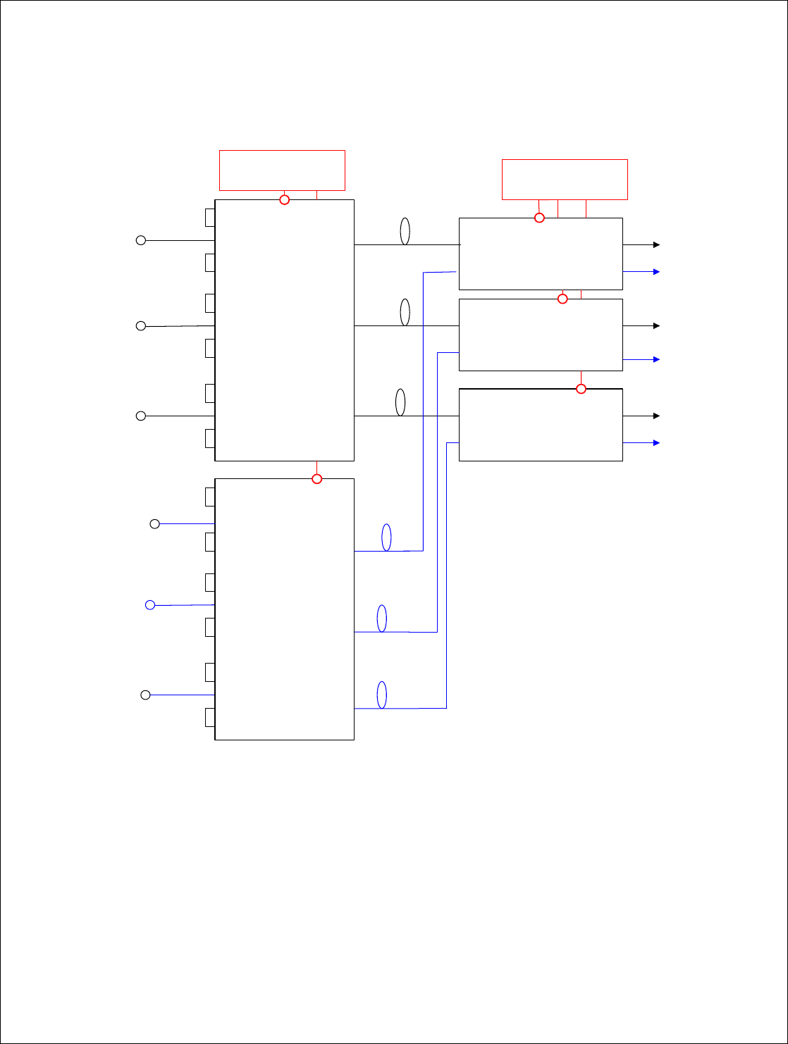
4.3 Fiber Transceiver Unit Block Diagram
POWER SUPPLY
CONTROLLER
FAN
FAN
RX
TX
OP / RF
RXout
RXin
BTS port
TXout
TXin
RX
TX
OP / RF
RX
TX
OP / RF
RF
BOARD
RF
BOARD
RF
BOARD
Optical 1
Optical 2
Optical 3
1
RXout
RXin
BTS port
TXout
TXin
RXout
RXin
BTS port
TXout
TXin
2
3
+5V
&CTRL
+12V
&CTRL
+12V
&CTRL
+12V
&CTRL
+5V
&CTRL
+5V
&CTRL
AC 90-250V,
15A
ETHERNET -
PROPRIETARY
RS485
Figure 7: FTU Block Diagram
Fiber-Span
Rev A Page 12 of 25
4.4 Fiber Transceiver Unit External Interfaces (with optional Duplexed Ports)
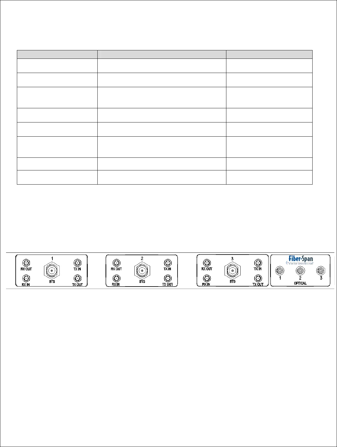
4.4.1 FTU Interface Description
Interface Description Limits, Max.
Rxout (1-2 and 3)
SMA FEMALE Rx output (separate Rx/Tx ; for low power
compact BTS)
RXin (1-2 and 3)
SMA FEMALE RX input from RXout when using diplexed Rx/Tx
Port connection.
BTS Port (1-2 and 3)
N-TYPE FEMALE TX and RX diplexed BTS Port Max. Input Power: 43dBm
Min. Input Power: 36dBm
Txout (1-2 and 3)
SMA FEMALE Tx output from BTS port when using diplexed
Rx/Tx Port connection
Txin (1-2 and 3)
SMA FEMALE Tx In
(separate Rx/Tx ; for low power compact BTS) Max. Input Power: 5dBm
Min. Input Power: -5dBm
Optical (1-2 and 3)
FC/ACP
Optical Input /output Port
Output to RFN on TX path
Input from RFN on RX path
ETHERNET
RS485 Communication Port
AC POWER IN 110/220
VAC Input Voltage Min. Input Voltage: 90V
Max. Input Voltage : 220V
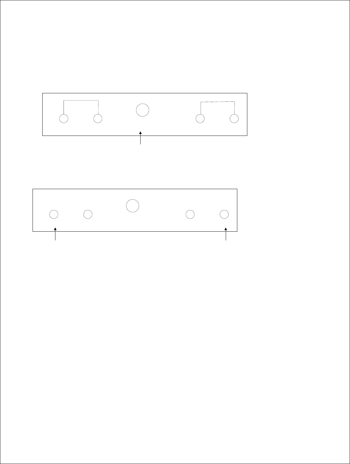
4.4.2 FTU Front Panel Description (show with optional Duplexed Ports)
Figure 8: FTU Front Panel
Fiber-Span
Rev A Page 13 of 25
Depending on the input configuration of the FTU, there are different connections required to the front panel :
1. TX/ RX diplexed
2. TX and RX separate
RXout RXin BTS Port TXout TXin
Input from BTS
connected here.
TX/RX Diplexed:
TX/RX Seperate:
RXout RXin BTS Port TXout TXin
Rx Ouput to BTS
connected here.
Tx Input to BTS
connected here.
TX/RX Seperate:
Figure 9: FTU Front Panel Configurations
Fiber-Span
Rev A Page 14 of 25
5. Dual Band Outdoor DAS System Connections
Following is a system connection diagram showing how to connect the 3 Remote Fiber Nodes and 2 FTUs for the Dual Band
Outdoor DAS. Connections shown with optional Duplexed input configuration.
To AWS
Antenna 1
From AWS
BTS Sector1
From AWS
BTS Sector 2
From AWS
BTS Sector 3
Fiber Optic
Links
From PCS
BTS Sector 1
From PCS
BTS Sector 2
From PCS
BTS Sector 3
To PCS
Antenna 1
To AWS
Antenna 2
To PCS
Antenna 2
To AWS
Antenna 3
To PCS
Antenna 3
RXout
BTS Port 1
RXin
TXout
TXin
RXout
BTS Port 2
RXin
TXout
TXin
AWS
HEC
RXout
BTS Port 3
RXin
TXout
TXin
Optical 1
Optical 2
Optical 3
Fiber
AWS
Fiber
PCS PCS
Antenna
AWS
Antenna
Remote
Node
Sector 1
Fiber
AWS
Fiber
PCS PCS
Antenna
AWS
Antenna
Remote
Node
Sector 2
Fiber
AWS
Fiber
PCS PCS
Antenna
AWS
Antenna
Remote
Node
Sector 3
RXout
BTS Port 1
RXin
TXout
TXin
RXout
BTS Port 2
RXin
TXout
TXin
AWS
HEC
RXout
BTS Port 3
RXin
TXout
TXin
Optical 1
Optical 2
Optical 3
Fiber Optic
Links
AC 90-240V
AC 90-240V
AC 90-240V
AC Supply
AC Supply
AC POWER IN
AC POWER IN
Figure 10: Dual Band Outdoor DAS System Connections
PCS
FTU
AWS
FTU
Fiber-Span
Rev A Page 15 of 25
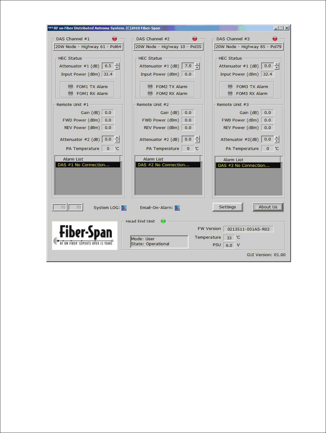
6. Dual Band Outdoor DAS Electrical Specifications
Electrical Requirements Specification PCS Specification AWS
DL ( TX) PCS AWS
Frequency of Operation 1930-1900MHz 2110 – 2155 MHz
RF Output Power 36 to 43 dBm 36 to 43 dBm
Gain 0 dB (Factory Set 0 dB, Field Adjustable) 0 dB (Factory Set 0 dB, Field Adjustable)
Emission Mask
Compliant to 3GPP2
(4xEDGE signal, spacing 600KHz)
Compliant to 3GPP2
(2 x CDMA2k signals, 20 MHz instantaneous
BW)
UP (Rx) PCS AWS
Frequency of Operation 1850-1910 MHz 1710-1755 MHz
Gain 6.0 dB
10 miles (13km) fiber length between FTU
and RFN.
6.0 dB
10 miles (13km) fiber length between FTU and
RFN
Noise Figure for G<5dB
5.0 dB 5.0 dB
IP3 -5 dBm -5 dBm
7. Monitoring & Control
The system can be monitored and controlled using the RS-485 interface. Following is a list of the monitoring and control features
that are available on this product.
Monitoring and Control Description & Specification
Monitoring Description Specification
Remote Fiber Node Forward
Output Power (RF) RF Output Power level (dBm) of the Remote Fiber
Node at Antenna port.
Remote Fiber Node
Reflected Power (RF) RF Reflected Power level (dBm) of the Remote
Fiber Node at Antenna Port.
Remote Fiber Node
Temperature Temperature (ºC) of the Remote Fiber Node
(controller board). ± 3 degrees
FTU Input Power (RF) RF input power level ( dBm) at the BTS input port
of the FTU.
FTU Temperature Temperature (ºC) of the FTU (RF board).
System Gain DL path gain (Tx) from the input to the FTU to the
output of the Remote Fiber Node.
Control
Remote Fiber Node Tx Path
Gain Control User Control – The customer can adjust the gain of
the Remote Fiber Node DL path (Tx) through the
GUI interface.

Fiber-Span
Rev A Page 16 of 25
Alarms
MCPA Alarm Alarm if any of the MCPA RF devices fail.
Power Supply Alarm Alarm if any of the power module ( DC/DC
converters) fail.
Temperature Alarm Alarm when temperature > 85 ºC.
LNA Current Alarm Alarm if current > 200mA on the LNA of the AWS
or PCS DLNA.
Default value is 200mA can be
modified by user
VSWR Alarm Alarm if at antenna port of Remote Fiber Node
Forward Output Power – Refelected Power < 5dB
Fiber Optic Module Alarm Alarm if one of the fiber optic module fails
Fan Failure Alarm Alarm if any of the fans fail
8. Graphic User Interface (GUI)
A Fiber-Span GUI is provided to control and monitor the performance of the Dual Band Outdoor DAS. The GUI can be
used to monitor 1 FTU and 3 Remote Fiber Nodes using a local connection.
The GUI that needs to be installed on the computer to monitor both the AWS and PCS FTUs.:
DAS GUI vX.YY.exe
Following are the steps required to install and run both GUIs.
Create a folder for each AWS and PCS and copy the corresponding GUI inside along with a copy of DAS-Profile.ini file
Install WinPcap software
Connect each FTU to a hub and to PC
Run both GUI from their new folders
GUI Interface – 1 FTU
In order for the GUI to communicate with the Dual Band Outdoor DAS, a cable needs to be connected between a PC/Laptop
and the FTU communication port – ETHERNET port. The FTU controller uses RS485 protocol on its ETHERNET port.
The FTU communicates with the Remote Fiber Node through Fiber Optic Link, no other connection is required to the
Remote Fiber Node to communicate with the GUI. The PCS GUI is required to connect to the PCS FTU and the AWS GUI is
required to connect to the AWS FTU. Therefore, there are two instances of the Fiber-Span GUI running at the same time to
monitor both FTUs.
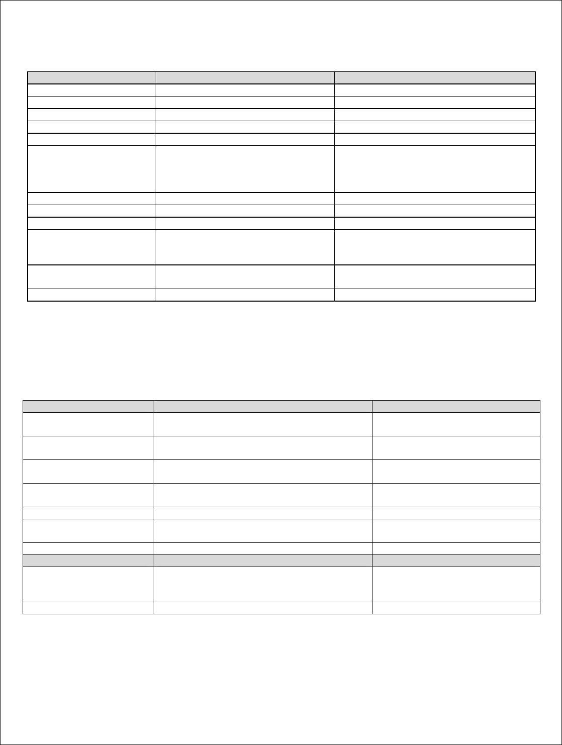
Following is the snapshot of the GUI, there are two pages which are displayed on the screen:
1. Settings Page: This is the page where all the settings for the network, e-mail server, and dialy logs are entered. This is the
first page to come up every time the user starts-up the GUI. It is also available from the Display Page using the
“Settings”button.
2. System Performance Page: This is where the DAS system performance parameters are displayed for 1 FTU.
Fiber-Span
Rev A Page 17 of 25
Figure 11: Fiber-Span GUI Settings Page
Geographical ID/Description:
Field to describe each Remote Fiber Node that is connected to the FTU, to be able to distinguish one from the other on the
display page.
DAS # 1: Unit that is physically connected to Optical 1 Port.
DAS # 2: Unit that is physically connected to Optical 2 Port.
DAS # 3: Unit that is physically connected to Optical 3 Port.
Email-On-Alarm Settings:
Check enable Box to Receive e-mail notification when an alarm arises. The client settings are the e-mail server settings that
the customer is using for the e-mail notification.
Daily Log Settings:
Check enable Box to log the performance display page at a particular interval.
ReadMe: Not Used.
Fiber-Span
Rev A Page 18 of 25
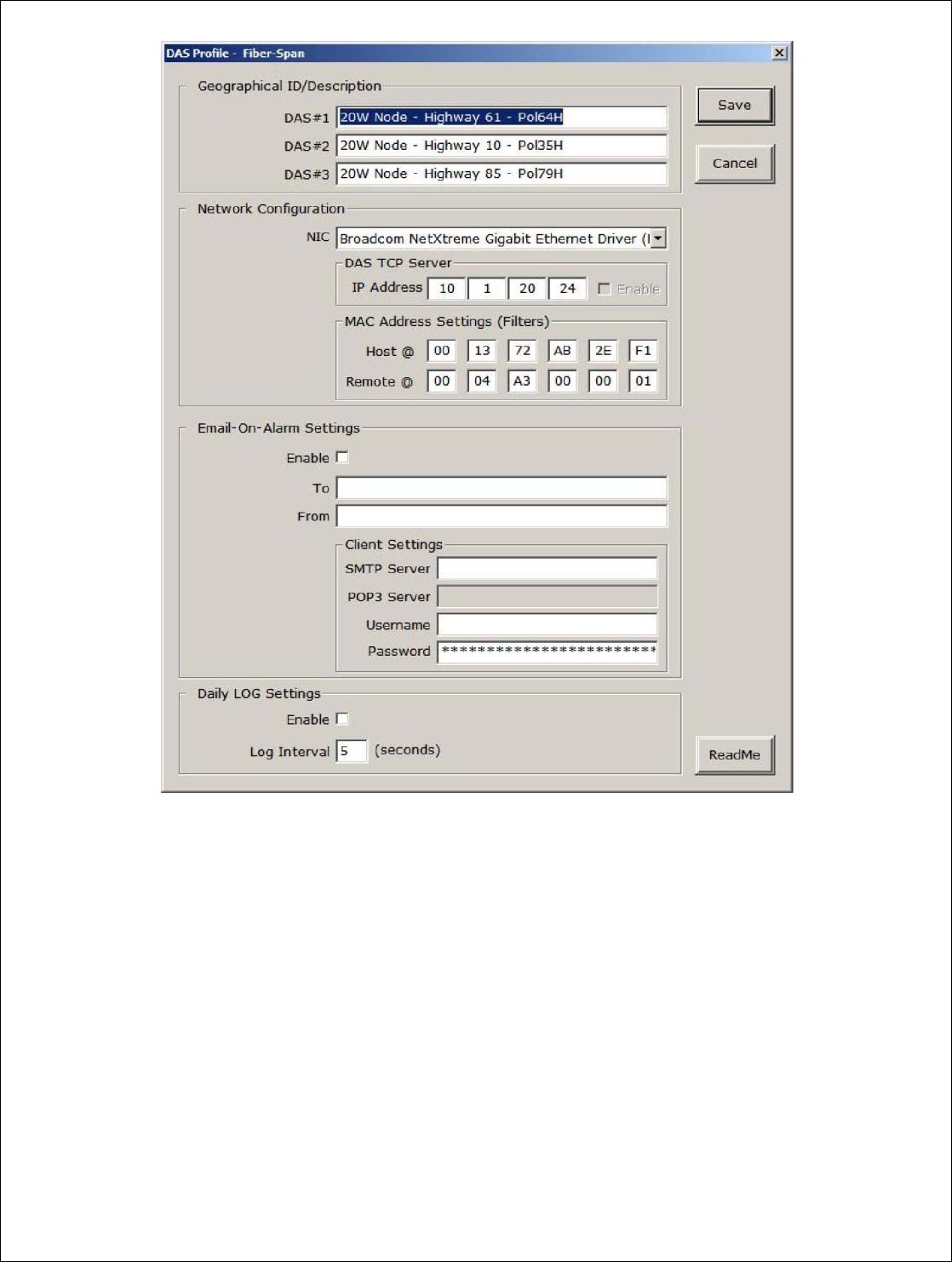
Figure 12: GUI System Performance Display Page
There are 4 sections on the DAS system performance page:
Head End Unit Section: System Performance parameters for the FTU
If the Head End Unit Button is Green, the communication with the FTU has been extablished.
FW Version: Firmware Version installed on the FTU
Temperature: Temperature in degrees celcius of the controller inside the FTU unit.
PSU: Power Supply Voltage Output
DAS Channel # 1, DAS Channel # 2 and DAS Channel # 3 Section: Performance parameters for the 3 individual Remote
Fiber Nodes.
If the DAS Channel # X is Green, the communication with the Remote Fiber Node has been established.
Underneath the DAS Channel # X is the description given to the Remote Fiber Node (from settings page).
FTU Status:
Attenuator # X: Setting for the digital attenuator of the FTU to control gain of the system.

Fiber-Span
Rev A Page 19 of 25
Input Power (dBm): Power level in dBm at the input of the FTU, BTS Port.
FOM1 TX Alarm and FOM1 RX Alarm: Alarm from Fiber Optic Module of the FTU, Tx / RX respectively.
Remote Unit # X:
Gain (dB): System Gain Calculated from the input to the FTU (BTS port) to the output of the Remote Fiber Node (Antenna
Port)
FWD Power (dBm): Power Level at the output of the Remote Fiber Node (Antenna Port)
REV Power (dBm): Power Level of power reflected back into the unit at the output of the Remote Fiber Node (Antenna Port)
Attenuator # 2: Setting for the digital attenuator of the Remote Fiber Node to control gain of the system.
PA Temperature: Temperature in degrees celcius of the MCPA inside the Remote Fiber Node unit.
Alarm List: List of Alarms currently active on the unit:
FAN 1 Alarm
FAN 2 Alarm
Fiber-Span
Rev A Page 20 of 25
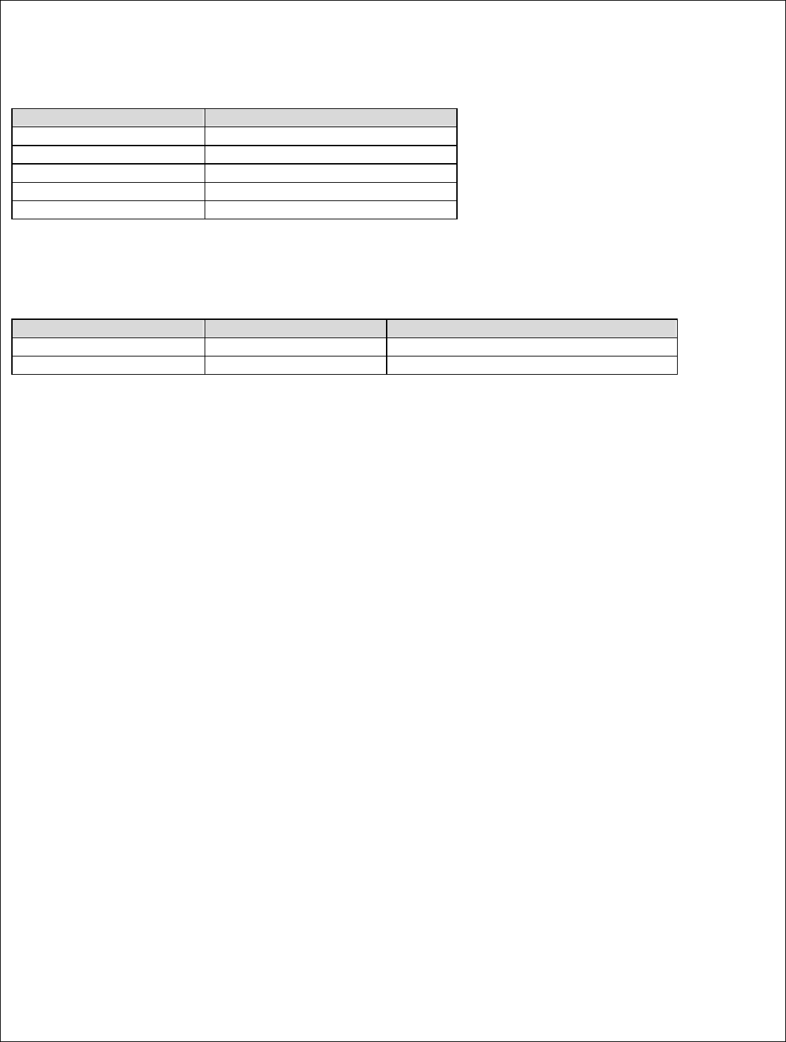
9. Mechanical Specifications
Mechanical Specification
Size 26.5”H x 13.2”W x 7.3”D
RF Connectors DIN
Control connector RJ-45
Optical Connector FC/APC
Finish Enamel Paint
10. Environmental Specifications
Environmental Specification Notes
Temperature of operation -40 to +45 Warm up of 20 minutes at -40
Enclosure IP65
11. Regulatory Statements:
“Changes or modifications not expressly approved by the manufacturer could “Void” the user’s authority to operate the equipment”.
This device has been designated to operate with antennas having a maximum gain of [14 ] dBi for a [ 5 ] meter distance and antennas
having greater values are strictly prohibited for use with this device. The required antenna impedance is [ 50 ] Ohms.

Fiber-Span
Rev A Page 21 of 25
12. Appendix A : Installation Instructions
Preparing for Installation
Before attempting to install, we recommend that you first familiarize yourself by reading through the installation instructions.
Understanding the system operation will reduce the possibility of incorrect installation, thereby causing damage or injury to
yourself or others.
The system must be installed in accordance with the conditions and recommendations contained
in the following sections.
Safety Precautions
Carelessness or mishandling of the DAS may damage the equipment causing serious injury to yourself or others. All installation
activity must be carried out in compliance with the safety instructions supplied with the BTS and with local standard authority
warnings and precautions.
Please adhere to the following:
WARNING!!
This equipment is designed for use with high power radio frequency (RF) radiating
systems. Personnel must take precautions to minimize exposure to the RF fields.
WARNING!!
The equipment is designed for use with equipment that generates high voltages.
Proper precautions must be taken when working with this equipment.
CAUTION!
To prevent damage to static sensitive devices, ESD (electrostatic discharge)
precautions must be observed when handling or installing the equipment.
Do not tamper with, or attempt to reconfigure, the cords or plugs supplied with
the hardware, as this can:
♦ result in personal injury
♦ void the warranty
♦ cause damage to the units or related equipment

Fiber-Span
Rev A Page 22 of 25
Warranty Information
Fiber-Span will warranty each product that it manufactures to be free from defects in materials and workmanship for a period of
twelve (12) months.
Fiber-Span’s only obligation under this warranty is to, at its option, repair or replace any product or part thereof that is returned
with transportation charges prepaid to Fiber-Span by the original purchaser within one year after delivery to the original
purchaser, and which, upon examination by Fiber-Span, is determined to be defective or to have failed the normal service.
Equipment Damage or Loss
Fiber-Span is not responsible for damage or loss of equipment during transit. For further information, contact the responsible
transport carrier.
When declaring equipment as damaged during transit, preserve the original shipping cartons to facilitate inspection reporting.
Return of Equipment
All warranty returns must be authorized by the Fiber-Span Customer Service Department, which will issue a Return Material
Authorization (RMA) number. This is important for prompt, efficient handling of the returned equipment and of the associated
complaint
When returning equipment to Fiber-Span for repair or replacement:
1. Notify Fiber-Span Customer Service Department of the equipment condition and obtain a Return Material
Authorization (RMA) number and shipping instructions at:
a. Email: sales@fiber-span.com
b. Telephone: (908) 253-9080
c. Fax: (908) 253-9086
2. Identify, in writing, the condition of the equipment.
3. Include to the Part Number, Serial Number, Sales Order, Purchase Order and the date the equipment was received.
Fiber-Span will pay for the cost of shipping the product to the customer after the repairs are completed.
Fiber-Span
Rev A Page 23 of 25
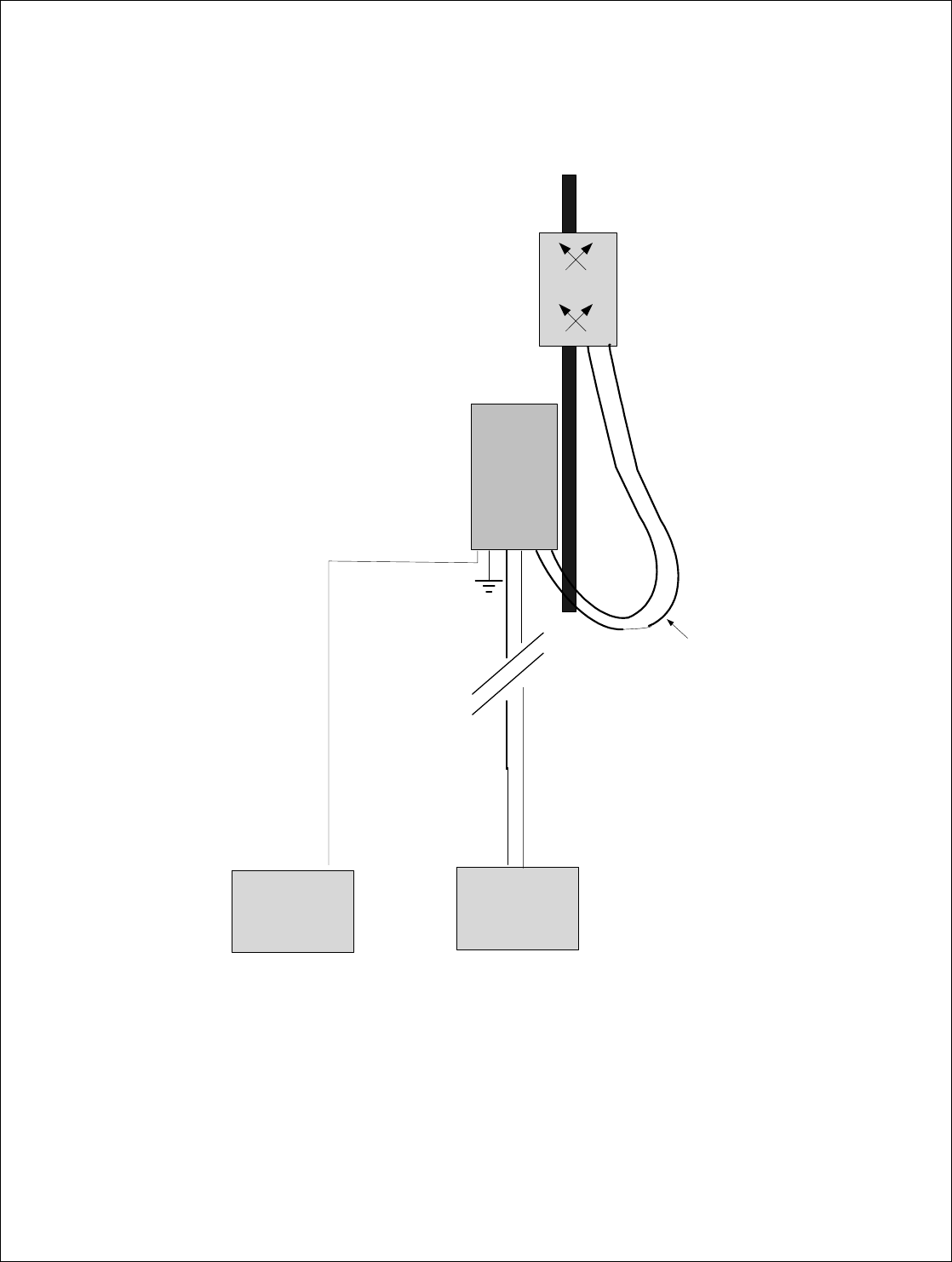
System Installation
DAS Remote Fiber Node System Block Diagram:
BTS
Equipment
Site AC
Supply
Drip Loop in
cable to
Antenna
ANTENNA
Note: System components not to scale
R E M O T E
NODE
Figure 13 – System Block Diagram
Fiber-Span
Rev A Page 24 of 25
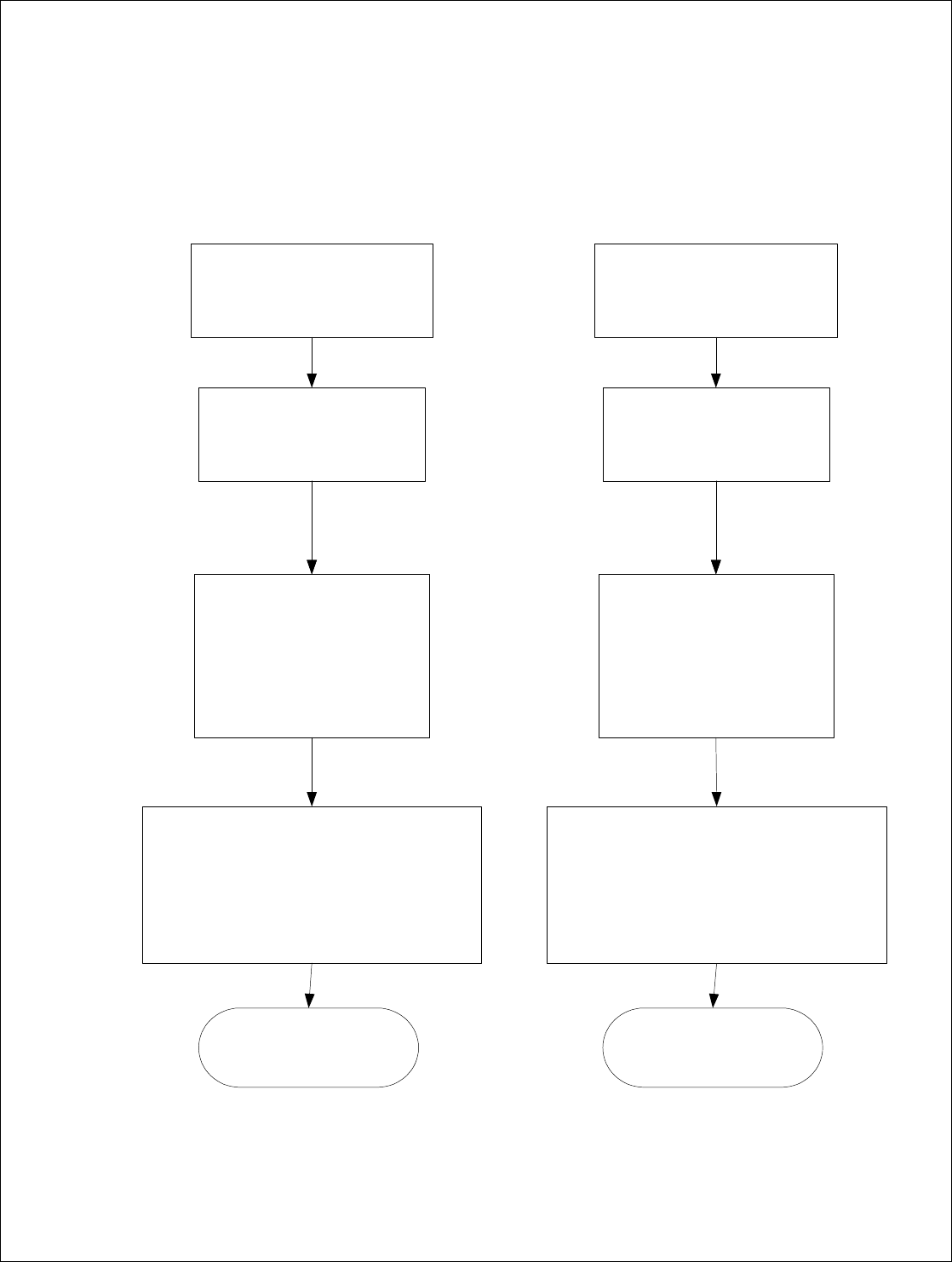
Installation Overview
The flow chart below illustrates the steps required to install the DDAS Remote Fiber Node and FTU. Details and graphic
explanations for the installation steps are shown in the following detailed installation sections, as indicated.
Close down the Antenna Site
Isolate the power source and ensure
the site is safe.
Secure Remote Node to tower or
surface, as desired. by completing
appropriate step sequence
detailed in section 3.3.1.
Connect feeder cables:
*AWS Antenna port to Antenna
* PCS Antenna por to Antenna
* Fiber Optic Link for PCS to Fiber
PCS port
* Fiber Optic Link for AWS to Fiber
AWS port
Connect ground cable
Connect power and control cables
* Manufacture and connect AC power cable from
BTS to Remote Nocde, as required.
Installation complete.
Proceed to Verification Testing
Close down the BTS cell
Isolate the power source and ensure
the site is safe.
Install PCS FTU and AWS FTU in
BTS Rack.
Connect feeder cables:
*BTS Sector 1, 2 and 3 to FTU
BTS Port 1, 2 and 3.
* Fiber Optic Link for PCS to PCS
FTU Optical 1, 2 and 3.
* Fiber Optic Link for AWS to AWS
FTU Optical 1,2 and 3 port.
Connect ground cable
Installation complete.
Proceed to Verification Testing
Connect power and control cables
* Manufacture and connect AC power cable from
BTS to FTU AC POWER IN port, as required.
* Connect BTS communication cable to FTU
ETHERNET port.
Remote Node FTU

Fiber-Span
Rev A Page 25 of 25
Detailed Installation Instructions
Remote Fiber Node Installation
The DAS Remote Fiber Node has been designed to be mounted outdoors directly on the antenna mast. If this is not feasible, it
may be mounted on a flat wall surface as close as possible to the associated antenna. Each DAS Remote Fiber Node comes
equipped with integrated mounting brackets which are used for either installation option .
Remote Fiber Node Verification Testing
Standard site testing done by the operator includes drive testing and base station Key Performance Indicators (KPI).