Fine Offset Electronics WH53 Temperature sensor User Manual WH0280
Fine Offset Electronics Co., Ltd. Temperature sensor WH0280
User Manual

InstructionManual
1
User Manual
Contents
1. Introduction...............................................................................................2
2. Get Started................................................................................................2
2.1 Parts List........................................................................................2
2.2 Recommend Tools.........................................................................3
2.3 Thermometer Sensor Set Up.......................................................3
2.4 Display Console Set Up................................................................3
2.4.1 Display Console Layout.............................................................5
2.4.2 Sensor Operation Verification...................................................5
3. Wireless Sensor Installation...................................................................5
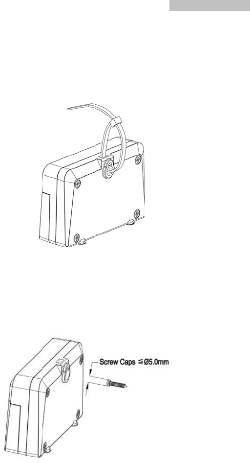
3.1 Mounting with Zip Tie....................................................................6
3.2 Mounting with Nail or Screw........................................................6
4. Console Operation...................................................................................7
4.1 Setting for 12/24hr Switch, Time and °C/°F Switch..................7
4.2 Setting for Alarm Clock.................................................................7
4.3 Setting for Min/Max Record..........................................................7
4.4 Setting for RF Channels...............................................................8
5.Sensor Resynchronization.......................................................................8
6.Best Practices for Wireless Communication.........................................9
7.Specifications............................................................................................9
7.1 Wireless Specifications.................................................................9
7.2 Measurement Specifications........................................................9
7.3 Power Consumption......................................................................9
8. FCC Statement.......................................................................................10
9. Warranty Information.............................................................................12
InstructionManual
2
1. Introduction
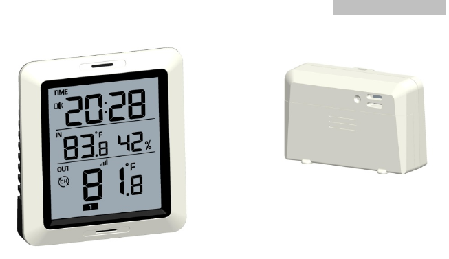
Thanks for your purch asing of the WH028 0 Wirel ess Indoor/Outdoor
Thermometer with Indoor Humidity . T o ensure the best product
performance, please read this ma nual and r etain it for future
reference.
2. Get Started
Note:Power up sequence must be performed in the order shown in this
section (insert batteries in the Re mote Sensor first, Display Console
second).
Attention:
Do not mix old and new batteries
Do not mix Alkaline, Standard, Lithium or Rechargeable batteries
Ensure batteries are installed correctly with regard to polarity +/-
2.1 Parts List
One Display Console (Receiver)
One remote sensor (Transmitter)
One User Manual
InstructionManual
3
2.2 Recommend Tools
Hammer for hanging remote thermometer transmitter.
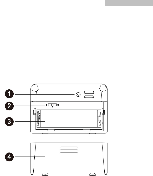
2.3 Thermometer Sensor Set Up
1. Remove the battery door on the ba ck of the sensor by sliding t he
compartment door down, as shown in Figure 1.
2. Set RF sensor channel.
Figure 1
1 Wireless transmitter LED
2 1, 2, 3 RF Channels
3 AA Battery
4 Battery Compartment Cover
3. Insert one AA battery.
4. After inserting the battery, the remote sensor LED indicator will light
for 4 seconds, and then flash once per 60 seconds thereafter. Each
time it flashes, the sensor is transmitting data.
5. Close the battery door.
2.4 Display Console Set Up
1. Move the remote thermo meter(s) abo ut 2 to 3m awa y from the
display console (if the sensor is too close, it may not be receive d
2
A
s
e
3
I
f
f
o
by the d
i
. Remov
e
Figure
2
in the b
a
A
ll of the L
C
e
gments ar
e
. Replace
the con
s
The con
The re
m
minutes
.
While in
f
the remot
e
o
r support.
i
splay cons
o
e
the batter
y
2
. Insert on
e
a
ck of the di
s
1.
2.
3.
4.
5.
6.
C
D segmen
t
e
operating
the batter
y
s
ole in the u
p
sole will ins
t
m
ote tempe
r
.
the search
e
does not
u
4
o
le).
y
door on th
e
e
AA (alkalin
s
play cons
o
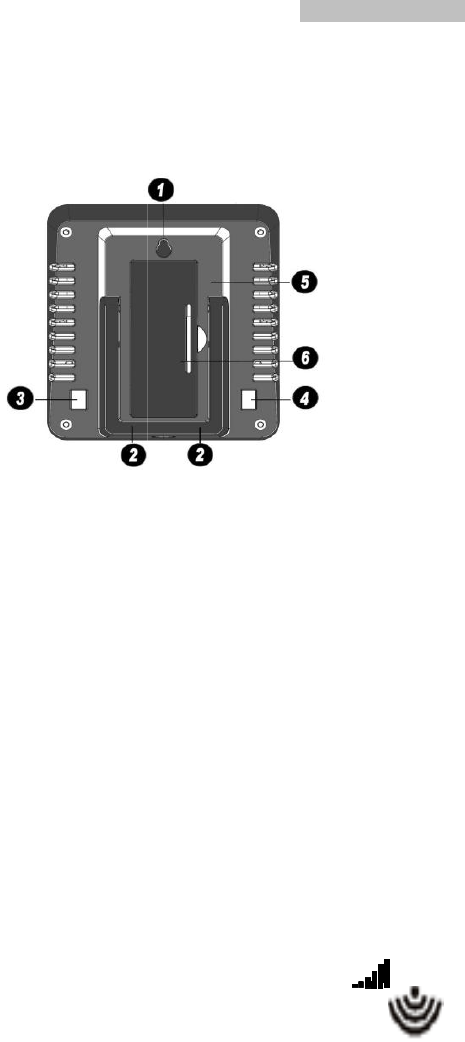
Fi
g
Integrated
Stand Mou
CH/+ Butt
o
Mode Butt
o
Battery Co
m
Battery Co
m
t
s will light
u
properl
y
.
y
do or, and
f
p
right positi
o
t
antly displ
a
r
ature will u
p
mode, the r
u
pdate, ple
a
e
back of t
h
e, lithium o
r
o
le.
g
ure 2
Hang Hole
H
nt
o
n
o
n
m
partment
m
partment
C
u
p for a fe
w
f
old out the
o
n.
a
y indoor te
m
p
date o n th
eception se
a
se contact
Instruc
t
h
e displa
y
,
a
r
rechargea
b
H
ang Hole
C
over
w
seconds
t
desk stan
d
m
perature a
n
e displa y
w
arch icon
our Custo
m
t
ionManual
a
s shown in
b
le) battery
t
o verify all
d
and place
n
d humidity.
w
ithin a fe w
flash.
m
er Service
InstructionManual
5
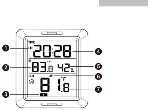
2.4.1 Display Console Layout
Figure 3
1. Alarm Clock Icon
2. Current Indoor Temperature
3. RF Channels
4. Time
5. Current Indoor Humidity
6. Outdoor Reception Icon
7. Current Outdoor Temperature
2.4.2 Sensor Operation Verification
Verify the in door a nd o utdoor temp erature mat ch closely with the
console and sensor arra y in the sa me location (about 2 to 3m apart).
The sensors should be within 2°F (the accuracy is ± 1°F). Allow about
30 minutes for both sensors to stabilize.
3. Wireless Sensor Installation
It is recommende d yo u mount the r emote sensor in a sha ded ar ea.
Direct sunlight and radi ant heat s ources will result in inaccurate
temperature readings. Although the sensor is water resistant, it is best
to mount in a well-protected area, such as under an eve.
3
M
m
w
3
To
e
.1 Mountin
g
M
ounting th
e
m
ounting ou
t
w
ill store an
d
.2 Mountin
g
To
mount th
e
qual to 5.0
m
g
with Zip
T
e
sensor wit
h
t
side, since
d
radiate he
a
g
with Nail
e
sensor wit
h
m
m in diam
e
6
T
ie
h
a zip tie w
it is not tou
c
a
t (or cold).
Figu
r
or Screw
h
a nail or s
c
e
ter.
Figu
r
ill result in
b
c
hing anoth
e
r
e 4
c
rew, the c
a
r
e 5
Instruc
t
b
etter accur
a
e
r object. O
t
a
p must be l
e
t
ionManual
a
cy when
t
her objects
e
ss than or

InstructionManual
7
4. Console Operation
Note: The console has two buttons for easy operation:【CH/+】 button
(on the left), and【MODE】button (on the right).
If no operation for 30s, display will return back to normal mode.
4.1 Setting for 12/24hr Switch, Time and °C/°F Switch
Long press【MODE】button 2s, step into setting mode.
a. Short press【CH/+】 switch 24/12hr display
b. Short press【MODE】,step into Hour setting, Short press【CH/+】
to adjust the number from 1-12 or 0-23.
c. Short press【MODE】,step into Minute setting, Short press【CH/+】
to adjust the number from 0-59.
d. Short press【MODE】, step into temperature unit setting, short press
【CH/+】to select°C/°F display.
e. Short press【MODE】, to complete setting mode and back to normal
mode.
4.2 Setting for Alarm Clock
Short press【MODE】button, step into alarm clock display setting mode,
short press 【CH/+】to enable ( spe aker icon is lit) or disable alar m
function.
a. Long press【MODE】button 3s, step into alarm Hour setting, Short
press【CH/+】to adjust the number from 1-12 or 0-23.
b. Short press【MODE】, step into alarm Minute setting, Short press
【CH/+】to adjust the number from 0-59.
Note: When the alarm clock is ringing, you can stop it by pressing any
button.
4.3 Setting for Min/Max Record

3
a
b
v
a
c
t
e
R
3
a
m
b
M
“
-
L
a
c
t
e
R
4
D
d
C
5
w
p
fi
W
.1 Min valu
e
. Short pre
s
. Short pre
s
a
lue (if no
e
. Long pr
e
e
mperature/
R
F channel.
.2 Max valu
. Short pre
s
m
ode.
. Short pres
M
ax valu e(i
f
-
-.-“ instead
)
ong press
nd the curr
e
. Long pr
e
e
mperature/
R
F channel.
.4 Setting
f
D
uring norm
a
isplay in th
e
C
H1 – CH2
–
5
.Sensor
R
w
hen the re
m
ress both th
ve second
s
W
hile in the
s
e
mode
s
s【MODE】
s
s【CH/+】
e
xtra outdoo
e
ss 【CH/
+
humidity a
n
e mode
s
s【MODE
】
s【CH/+】to
f
no extra
)
.
【CH/+】 fo
e
nt
e
ss 【CH/
+
humidity an
f
or RF Cha
n
a
l display m
e
following s
–
CH3 –
R
esynchr
o
m
ote senso
r
e 【CH/+】
s
.
s
earch mod
e
8
for twice,
s
to select o
t
r sensor av
a
+
】2s ,
r
n
d the curre
】
for three
t
select othe
outdoor
s
r 2s,reset th
+
】2s ,r
e
d the curre
n
n
nels
ode, press
equence:
o
nization
r
lost recep
t
and 【MO
D
e
, the rece
p
s
tep into Mi
n
t
her availab
a
ilable, it wil
r
eset the
M
nt displaye
d
t
imes step i
r available
o
s
ensor av
a
e Max valu
e
e
set the
M
n
t displaye
d
【CH/+】t
o
t
ion or extr
a
D
E】 butto
n
p
tion search
Instruc
t
n
value displ
le outdoo r
s
l display “--.
M
in value
d
Min value
nto Max v
a
o
utdoor sen
s
a
ilable, it
w
e
of indoor t
e
M
ax value
d
Max value
o
select out
d
a
sensors to
n
s at the sa
m
icon
f
t
ionManual
ay mode.
s
ensor Min
-“ instead).
of indoor
of outdoor
lue display
s
or channel
w
ill display
e
mperatu
r
e
of indoor
of outdoor
d
oor sensor
be added,
m
e time for
f
lash.

InstructionManual
9
6.Best Practices for Wireless Communication
Note: To insure proper communication, mount the remote sensor on a
vertical surface, such as a wall. Do not lay the sensor flat.
Keep the console several feet away from computer monitors and TVs.
7.Specifications
7.1 Wireless Specifications
Line of sight wirele ss transmission (in open air ):
300feet(100meters)
Frequency: 433.92 MHz
Update Rate: 60 seconds
7.2 Measurement Specifications
The followi ng table p rovides spec ifications for the me asured
parameters.
Measurement Range Accuracy Resoluti
on
Indoor
temperature
14 to 140 °F ± 1 °F 0.1 °F
Outdoor
Temperature
-40 to 140 °F ± 1 °F 0.1 °F
Indoor Humidity 1 to 99 % ± 3% (20% to 90%) 1 %
7.3 Power Consumption
Base station (display co nsole) : 1 x AA Alkaline or Lithiu m
batteries (not included)
Remote sensor : 1 x AA 1.5V Alkaline or Lithium batteries (not
included)

InstructionManual
10
8. FCC Statement
Statement according to FCC part 15.19:
This device complies with part 15 of the FCC rules. Operation is
subject to the following two
conditions:
1. This device may not cause harmful interference.
2. This device must accept any interference received, including
interference that may cause
undesired operation.
Statement according to FCC part 15.21:
Any changes or Modifications not expressly approved by this company
could void the user's authority to
operate the equipment.
Statement according to FCC part 15.105:
NOTE: This equipment has been tested and found to comply with the
limits for a Class B digital
device, pursuant to Part 15 of the FCC Rules. These limits are
designed to provide reasonable
protection against harmful interference in a residential installation. This
equipment generates, uses and
can radiate radio frequency energy and, if not installed and used in
accordance with the instructions,
may cause harmful interference to radio communications.
However, there is no guarantee that interference will not occur in a
particular installation. If this
equipment does cause harmful interference to radio or television
reception, which can be determined
by turning the equipment off and on, the user is encouraged to try to
correct the interference by one or

InstructionManual
11
more of the following measures:
• Reorient or relocate the receiving antenna.
• Increase the separation between the equipment and receiver.
• Connect the equipment into an outlet on a circuit different from that
to which the receiver is connected.
• Consult the dealer or an experienced radio/TV technician for help.
This device complies with FCC radiation exposure limits set forth for
an uncontrolled environment and
it also complies with Part 15 of the FCC RF Rules. This equipment
must be installed and operated in
accordance with provided instructions and the antenna(s) used for this
transmitter must be installed to
provide a separation distance of at least 20 cm from all persons and
must not be co-located or operating in
conjunction with any other antenna or transmitter. End-users and
installers must be provided with antenna
installation instructions and consider removing the no-collocation
statement.

InstructionManual
12
9. Warranty Information
We disclaim any responsibility for any technical error or printing
error, or their consequences.
All trademarks and patents are recognized.
We provide a 1-year limited warranty on this product against
manufacturing defects in materials and workmanship.
This limited warranty begins on the original date of purchase, is valid
only on products purchased and only to the original purchaser of this
product. To receive warranty service, the purchaser must contact us
for problem determination and service procedures.
This warranty covers only actual defects within the product itself, and
does not cover the cost of installation or removal from a fixed
installation, normal set-up or adjustments, claims based on
misrepresentation by the seller or performance variations resulting
from installation-related circumstances.