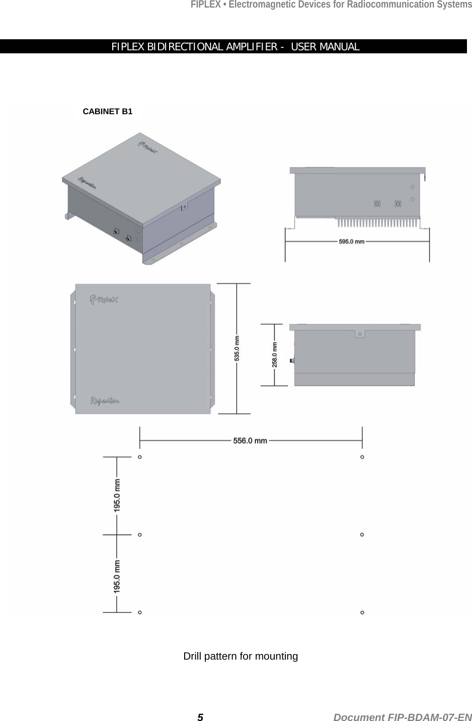
Fiplex Communications BDA85S-1B3LC ESMR BI-DIRECTIONAL AMPLIFIER User Manual INSTRUCCIONES DE CONEXI N
Fiplex Communications Inc ESMR BI-DIRECTIONAL AMPLIFIER INSTRUCCIONES DE CONEXI N
UserManual.wiki
>
Fiplex Communications
>
BDA85S 1B3LC User Manual
Users Manual
Navigation menu
Upload a User Manual
Namespaces
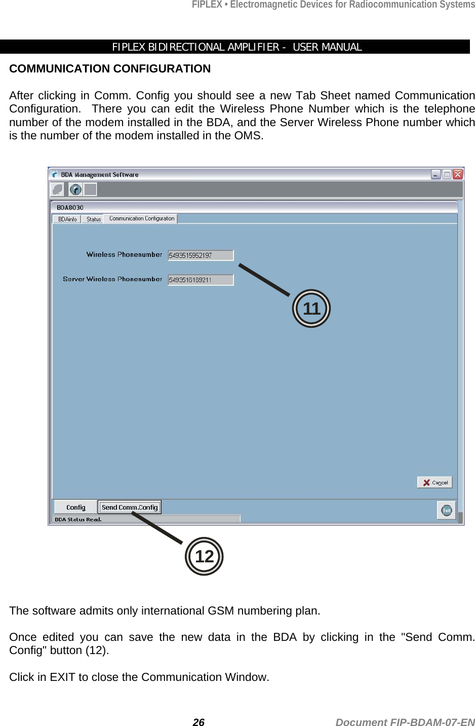
Wiki Guide
HTML
PDF
Info
Views
User Manual
Discussion / Help
Navigation