Fiplex Communications BDA85S-1B3LC ESMR BI-DIRECTIONAL AMPLIFIER User Manual INSTRUCCIONES DE CONEXI N
Fiplex Communications Inc ESMR BI-DIRECTIONAL AMPLIFIER INSTRUCCIONES DE CONEXI N
Users Manual
FIPLEX • Electromagnetic Devices for Radiocommunication Systems
1 Document FIP-BDAM-07-EN
FIPLEX BIDIRECTIONAL AMPLIFIER - USER MANUAL

FIPLEX • Electromagnetic Devices for Radiocommunication Systems
FIPLEX BIDIRECTIONAL AMPLIFIER - USER MANUAL
THIS PAGE HAVE BEEN LEFT INTENTIONALY IN BLANK
FIPLEX COMMUNICATIONS, INC. M.E.BRAUN-FIPLEX
7331 N.W. 54th Street S. Cabral 1242
Miami, FL 33166 (5006) Córdoba
U.S.A. Argentina
Ph: (305)884-8991 Tel: (54-351)456-8263
Fax: (305)884-4041 Fax: (54-351)456-2507
E-mail: info@fiplex.com E-mail: info@fiplex.com
2 Document FIP-BDAM-07-EN

FIPLEX • Electromagnetic Devices for Radiocommunication Systems
FIPLEX BIDIRECTIONAL AMPLIFIER - USER MANUAL
INDEX
Technical specifications. …………………………………………… Page. 4
Installation Instructions. ……………………………………………. Page. 6
Commissioning ……………………....................………………….. Page. 10
Downlink gain setup...………………………………………………. Page. 12
Uplink gain setup …………………………………………………… Page. 13
Alarms ……………………………………………………………….. Page. 16
Remote Management and Control System
Remote Management and Control Module .…………….. Page. 17
FIPLEX BDA Local Management Software
Overview..……………………………...........……………… Page. 19
Installation Instructions ……………………………………. Page. 19
Operation ………………………...............................…….. Page. 20
BDA Information...............................................………….. Page. 22
BDA Status.......................………………………………….. Page. 23
BDA Configuration .………………………...……………….. Page. 24
Communication Configuration……………………………… Page. 26
3 Document FIP-BDAM-07-EN
FIPLEX • Electromagnetic Devices for Radiocommunication Systems
FIPLEX BIDIRECTIONAL AMPLIFIER - USER MANUAL
TECHNICALL SPECIFICATIONS
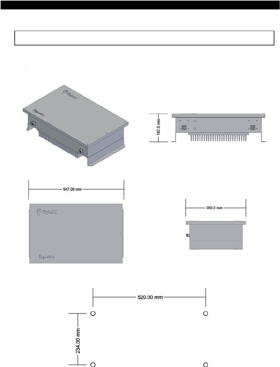
Mechanical dimensions
CABINET A1
Drill pattern for mounting
4 Document FIP-BDAM-07-EN
FIPLEX • Electromagnetic Devices for Radiocommunication Systems
FIPLEX BIDIRECTIONAL AMPLIFIER - USER MANUAL
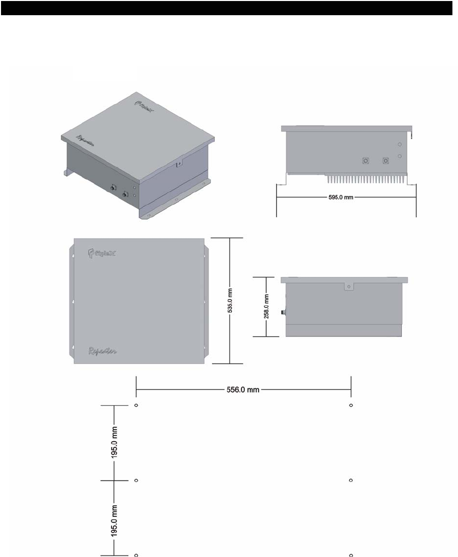
CABINET B1
Drill pattern for mounting
5 Document FIP-BDAM-07-EN
FIPLEX • Electromagnetic Devices for Radiocommunication Systems
FIPLEX BIDIRECTIONAL AMPLIFIER - USER MANUAL
INSTALLATION INSTRUCTIONS
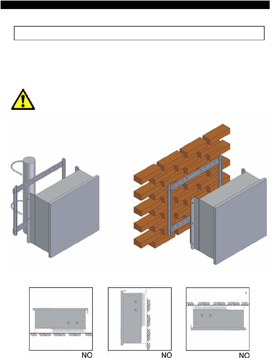
Mounting considerations.
BDA is provided in a closed cabinet, with six fixing holes for wall mounting (Mounting
brackets are not provided with BDA).
BDA should be mounted with input/output connectors facing down in order to
preserve water tightness.
Roof
Wall
Floor
6 Document FIP-BDAM-07-EN
FIPLEX • Electromagnetic Devices for Radiocommunication Systems
FIPLEX BIDIRECTIONAL AMPLIFIER - USER MANUAL
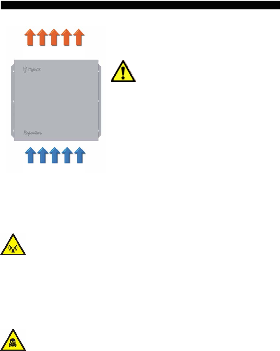
Natural convection flow should be
guaranteed trough heat dissipator in order to
keep repeater temperature between safety
margins (-30°C to +60°C).
Keep minimum distance of 15 cm between
heat dissipator and any object that could
avoid free airflow circulation.
Cold air
Hot ai
r
Safety
Any personnel involved in installation, operation or service of Fiplex repeaters
must understand and obey the following:
Repeaters are designed to receive and amplify signals from one or more base
stations and retransmit the signals to one or more mobile stations, and vice versa.
The repeaters must be used exclusively for these purposes and nothing else
• Repeaters supplied from AC voltage must be connected to ground to guarantee
safety operational conditions and to preserve the equipment.
• Repeaters generate radio signals and thereby give rise to electromagnetic fields
that could be hazardous to the health of any person who is extensively exposed to
the signals at the immediate proximity of the repeater antennas.
Coaxial cables insulation is made of polytetrafluoro ethylene, that could gives off
small quantities of hydrogen fluoride when heated. Hydrogen fluoride is
poisonous. Do not use heating tools when stripping coaxial cables insulation.
7 Document FIP-BDAM-07-EN
FIPLEX • Electromagnetic Devices for Radiocommunication Systems
FIPLEX BIDIRECTIONAL AMPLIFIER - USER MANUAL
AC Power
THE POWER SUPPLY UNIT CONTAINS DANGEROUS VOLTAGE THAT CAN
CAUSE ELECTRIC SHOCK.
DISCONNECT THE MAINS PRIOR TO ANY WORK IN THE REPEATER.
AUTHORIZED SERVICE PERSONNEL ONLY ARE ALLOWED TO SERVICE
REPEATERS WHILE THE MAINS IS CONNECTED.
Mains should be 110-220 VAC 50-60 Hz with ground terminal connection (yellow
and green cable).
A good ground connection must be done in order to preserve the equipment and
system reliability.
A 2 Amps fuse (5 x 20mm) is used as power supply protection against severe
failure in mains power.
DANGER
ALWAYS REMOVE MAINS POWER BEFORE CHECKING OR CHANGING FUSES.
120 VAC CAN BE LETHAL.
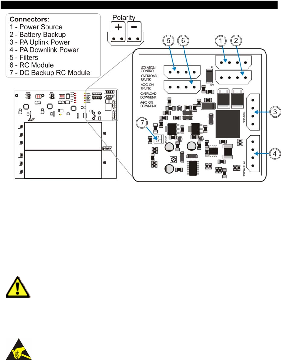
DC Power
There is an alternative way to power the repeater, this is by means of a DC power
source. DC power must be feed to the repeater main board by means of a specific
connector (please see figure below). Accessing the repeater from the outside with the DC
power cord must be done through the cable gland labeled “BATERY BACKUP”.
Nominal DC voltage is specified in the repeater datasheet specifications.
When DC voltage goes under the 80% of the nominal voltage, system will be in
BATTERY FAIL status.
8 Document FIP-BDAM-07-EN
FIPLEX • Electromagnetic Devices for Radiocommunication Systems
FIPLEX BIDIRECTIONAL AMPLIFIER - USER MANUAL
Power connectors – Check polarity before connect
In the presence of AC power, the system switchs automatically from DC power to
AC power in order to preserve battery charge.
Battery backup system is not provided with the repeater, nominal voltages and
currents should be observed in order to prevent from malfunction. See specification sheet.
For further assistance please contact factory.
VERIFY THAT CABLE GLAND IS WELL FITTED IN ORDER TO PRESERVE
WHEATER TIGHTNESS OF THE REAPETER.
Static electricity means a potential source of permanent damage for essential parts
of the repeater, if not handled carefully.
NEVER TOUCH PRINTED CIRCUIT BOARDS OR UNINSULATED
CONDUCTIVE SURFACES WITHOUT PROPER ELECTROSTATIC
DISCHARGE PROTECTION.
9 Document FIP-BDAM-07-EN

FIPLEX • Electromagnetic Devices for Radiocommunication Systems
FIPLEX BIDIRECTIONAL AMPLIFIER - USER MANUAL
COMMISSIONING
Repeater powers on when the mains is connected to the AC line, or if it’s available,
when connected to a DC power source.
No further field calibration or tune up of the repeater is needed to work properly.
Repeaters are factory aligned and calibrated and are designed to retain calibration
throughout the life of the product.
Cover of the repeater must be always closed in order to preserve it from the
environment and to assure reliability.
When sited outdoors, repeater must not be opened in the following bad weather
conditions such as:
• Intense rainfall, snowfall or hail.
• Storm or high wind.
• Extremely low or high temperature.
• High humidity of the air.
Connection
Connect the service antenna to the input/output N type female connector labeled
“TO MOBILES”.
Connect the donor antenna to the input/output N type female connector labeled
“TO BASE”.
Radiant system, antennas and coaxial cables to be used with the repeater must be
adequate to work properly in the operation frequency bandwidth of the repeater.
At least 18dB return loss value should be observed at the service and donor
antennas connectors.
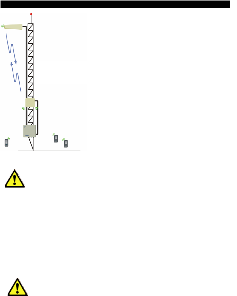
Antenna Isolation
ISOLATION BETWEEN DONOR AND SERVICE ANTENNAS MUST BE 20 dB
HIGGER THAN THE MAXIMUM GAIN OF THE REPEATER.
10 Document FIP-BDAM-07-EN
FIPLEX • Electromagnetic Devices for Radiocommunication Systems
FIPLEX BIDIRECTIONAL AMPLIFIER - USER MANUAL
Isolation between
Donnor and
Service antenna
If the isolation is less than the amplifier gain plus
20dB safety margin, then positive feedback sufficient for
oscillation is present in the system. Such oscillations
will overdrive one or both amplifier chains and
continuously activate the AGC and overload circuitry,
shutting down amplifiers in order to prevent them from
damage.
Poor isolation can cause permanent damage to
the repeater and automatically voids warranty
conditions.
DO NOT POWER THE REPEATER IF “TO BASE” AND “TO MOBILE”
CONNECTORS ARE NOT CONNECTED TO A RADIANT SYSTEM OR IF
THEY ARE NOT TERMINATED WITH PROPER LOADS.
Every time the repeater is powered on, it starts an automatic antenna isolation
control procedure. This procedure takes around 30 seconds, during this time the repeater
is not available for traffic, after the procedure is finished two things can occur:
- Good isolation between antennas, in this case isolation control alarm will not be
present and the repeater can be operated at maximum gain.
- Poor or bad isolation between antennas, isolation control alarm will be present
and the system will set repeater gain to a safe value, the repeater can not be
operated at maximum gain.
WHILE ISOLATION CONTROL IS PERFORMED THE PRESENCE OF
UPLINK SIGNALS SHOULD BE MINIMIZED. AVOID DE USE OF MOBILE
DEVICES NEARBY THE REPEATER DURING ISOLATION CHECK.
11 Document FIP-BDAM-07-EN
FIPLEX • Electromagnetic Devices for Radiocommunication Systems
FIPLEX BIDIRECTIONAL AMPLIFIER - USER MANUAL
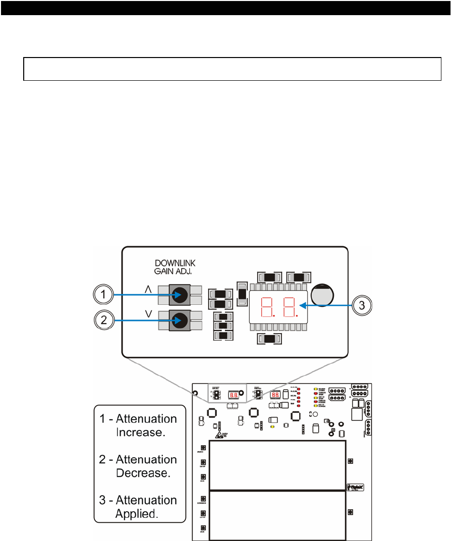
DOWNLINK GAIN SETUP
Manual Gain Setup
Downlink gain control is achieved setting up the desired attenuation value by
means of tact switches, value of attenuation is displayed in two seven segments displays
located at the right of the attenuation controls (please see figure below).
Attenuation values runs from 0dB (nominal gain condition), up to 25dB (maximum
attenuation or minimum gain), in steps of 1dB. If isolation level between antennas is not
enough, repeater automatically sets the maximum gain value allowed in order to prevent
unwanted oscillations. Under this circumstances user will not be able to set attenuation
values that may take the repeater to a non secure operating condition (usually nominal
gain is never achieved).
Downlink gain manual control
12 Document FIP-BDAM-07-EN

FIPLEX • Electromagnetic Devices for Radiocommunication Systems
FIPLEX BIDIRECTIONAL AMPLIFIER - USER MANUAL
If “AGC ON” led indicator is on when the repeater starts operating, this means that
signal received from the donor site is above minimum signal level required for nominal
gain operation so AGC circuitry is active.
Under this condition of operation user should attenuate the gain level of the
repeater using DOWN control, decreasing gain until “AGC ON DOWNLINK” indicator turns
off. This operation is recommended in order to release dynamic range to the AGC
circuitry.
Automatic Gain Control (AGC)
Automatic Gain Control circuitry is intended to keep repeater’s output power at a
fixed level when input signals exceed maximum values, avoiding quality signal degradation
by intermodulation generation.
If “AGC ON Downlink” led is on this means that signal level from donnor site plus
repeater gain produces an output power that is above the maximum composite output
power of the repeater. This should not be considered an undesired working condition, far
from that; this is the best operating condition because you are getting the maximum
composite output power available from the repeater.
Anyway is a good practice (if manual attenuator is set to a value different from
zero), to increase attenuation (reducing gain), until AGC led turns off, this operation
releases AGC circuitry dynamic range.
Also is a good practice to check signals from donor site to ensure that undesired
signals are not being amplified by the repeater, or even desired signal levels are not
excessively high taking repeater to an overload condition.
Overload Protection
When the automatic gain control circuit reaches its limit (20 dB), the power
amplifier stage is shut down to prevent harmful distortion and potential damage to the
repeater. After approximately ten seconds the system checks if overload condition is still
present, if this happens amplifiers will remain off. This cyclic check will continue until
condition that makes AGC circuitry reach its limits desapears.
Conditions that can cause AGC to reach its limits include the presence of one or
more very strong channels, a strong in-band noise source, or amplifier oscillation due to
poor antenna isolation.
When overload protection is active led labeled “OVERLOAD DOWNLINK” is on.
13 Document FIP-BDAM-07-EN
FIPLEX • Electromagnetic Devices for Radiocommunication Systems
FIPLEX BIDIRECTIONAL AMPLIFIER - USER MANUAL
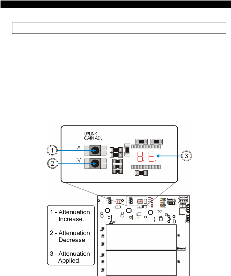
UPLINK GAIN SETUP
Manual Gain Setup
Uplink gain control is achieved setting up the desired attenuation value by means
of tact switches, value of attenuation is displayed in two seven segments displays located
at the right of the attenuation controls (please see figure below).
Attenuation values runs from 0dB (nominal gain condition), up to 25dB (maximum
attenuation or minimum gain), in steps of 1dB. If isolation level between antennas is not
enough, repeater automatically sets the maximum gain value allowed in order to prevent
unwanted oscillations. Under this circumstances user will not be able to set attenuation
values that may take the repeater to a non secure operating condition (usually nominal
gain is never achieved).
Uplink gain manual control
14 Document FIP-BDAM-07-EN

FIPLEX • Electromagnetic Devices for Radiocommunication Systems
FIPLEX BIDIRECTIONAL AMPLIFIER - USER MANUAL
Automatic Gain Control (AGC)
Automatic Gain Control circuitry is intended to keep repeater’s output power at a
fixed level when input signals exceed maximum values, avoiding quality signal degradation
by intermodulation generation.
Signals received from mobiles have a different nature that the ones received from
donor site or BTS, so it is rare that “AGC ON Uplink” led keeps on, if this occur, repeater
gain should be decreased. Is a good practice to set identical gain values in both (uplink
and downlink) paths to keep a good link budget balance, so is very recommended to take
downlink manual gain value as a reference for the uplink path. This balanced operation
mode prevents BTS desensitation or saturation from uplink signals amplified by the
repeater.
Overload Protection
When the automatic gain control circuit reaches its limit (20 dB), the power
amplifier stage is shut down to prevent harmful distortion and potential damage to the
repeater. After approximately ten seconds the system checks if overload condition is still
present, if this happens amplifiers will remain off. This cyclic check will continue until
condition that makes AGC circuitry reach its limit desapears.
Conditions that can cause AGC to reach its limit include the presence of one or
more very strong channels, a strong in-band noise source, or amplifier oscillation due to
poor antenna isolation.
When overload protection is active led labeled “OVERLOAD UPNLINK” is on.
15 Document FIP-BDAM-07-EN
FIPLEX • Electromagnetic Devices for Radiocommunication Systems
FIPLEX BIDIRECTIONAL AMPLIFIER - USER MANUAL
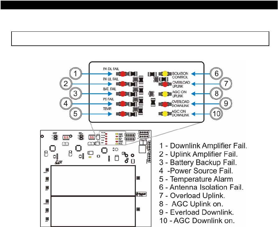
ALARMS
Alarm led indicators
The following alarms are available for this repeater:
• PA (DL/UL) FAIL: ON condition indicates amplifier failure condition and/or overload.
• TEMP: ON when maximum temperature operation condition is reached.
• BAT FAIL: ON when voltage is below nominal value, no battery conection is indicated
as a fail condition.
• PS FAIL: ON indicates power supply failure.
• ISOLATION CONTROL: ON when not enough isolation is achieved. Repeater can not
be operated at nominal gain.
16 Document FIP-BDAM-07-EN
FIPLEX • Electromagnetic Devices for Radiocommunication Systems
FIPLEX BIDIRECTIONAL AMPLIFIER - USER MANUAL
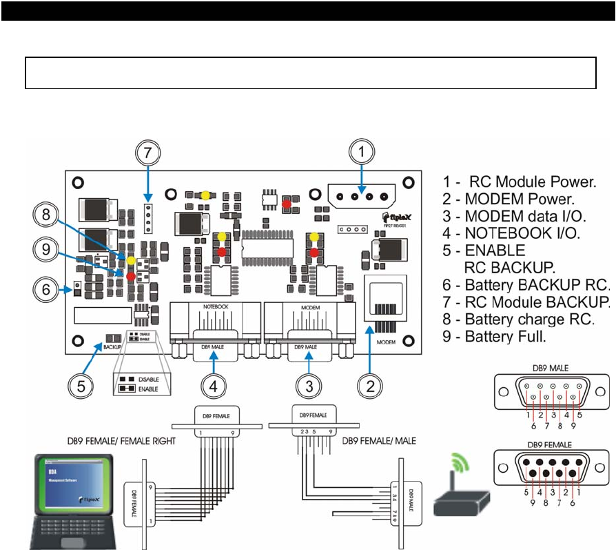
REMOTE CONTROL MODULE (RC)
Remote control module has an RS-232 interface with a D-Sub type 9 posittions
male connecto labeled as “NOTEBOOK” that allows a notebook conection by means of a
DB9 female straight cable.
Configuration of the repeater can be accomplished using BDA Local Management
Software (please see BDA LOCAL MANAGEMENT SOFTWARE section for further
details).
A modem conection is also available in the same module allowing the repeater to
be controlled and configured remotely by means of a wireless conection.
This module is able to work under mains failure condition by means of its own
backup battery, allowing the repeater to report this critical condition.
Backup battery must be enabled taking the jumper to the “ENABLE” position (see
above figure), factory default condition is disabled.
Battery provides autonomy of approximately 3 hours of continuous operation
approximately.
17 Document FIP-BDAM-07-EN
FIPLEX • Electromagnetic Devices for Radiocommunication Systems
FIPLEX BIDIRECTIONAL AMPLIFIER - USER MANUAL
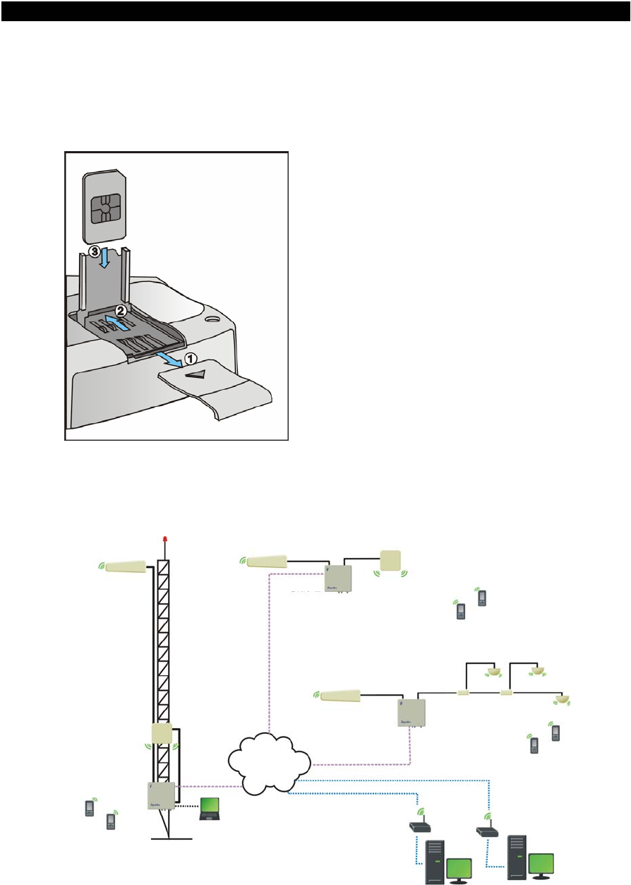
In repeaters with GSM modem (RC-G option) SIM card must be inserted as
described in the following picture.
SIM card insertion.
1- Remove SIM card cover.
2- Pull back and lift cardholder.
3- Insert SIM card into cardholder.
4- Push down and backwards
cardholder and place cover.
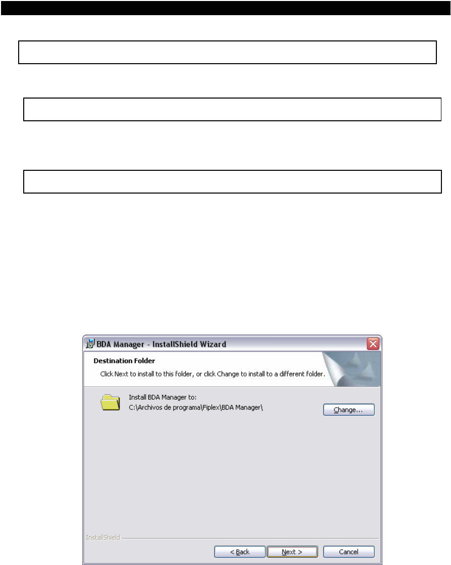
A repeater network could be managed and controlled using FIPLEX BDA Remote
Management Software. With this software centralized remote alarm monitoring and
repeater configuration is possible (see FIPLEX BDA Remote Management Software
section for further details).
NET
Site 3
Site 2
Site 1
18 Document FIP-BDAM-07-EN
FIPLEX • Electromagnetic Devices for Radiocommunication Systems
FIPLEX BIDIRECTIONAL AMPLIFIER - USER MANUAL
BDA LOCAL MANAGEMENT SOFTWARE
OVERVIEW
The BDA Local Management Software is a PC computer program that allows controlling a
BDA repeater locally using a Laptop computer.
Follow these steps to install the software:
INSTALLATION
1) Insert the Installation CD.
2) Execute BDAManagerSetup.exe.
3) Fill the user and organization Information.
4) Choose the folder where the software will be installed. You can use the default folder or
modify it by clicking in "Change".
Continue clicking in the Next button until the installation is completed.
You could also receive The BDA Manager software alone which doesn't require to be
installed.
19 Document FIP-BDAM-07-EN
FIPLEX • Electromagnetic Devices for Radiocommunication Systems
FIPLEX BIDIRECTIONAL AMPLIFIER - USER MANUAL
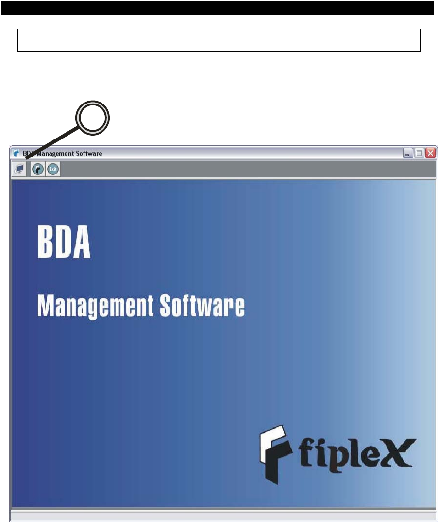
OPERATION
1) Execute the BDA Manager software and click in Connect to BDA Icon
1
20 Document FIP-BDAM-07-EN
FIPLEX • Electromagnetic Devices for Radiocommunication Systems
FIPLEX BIDIRECTIONAL AMPLIFIER - USER MANUAL
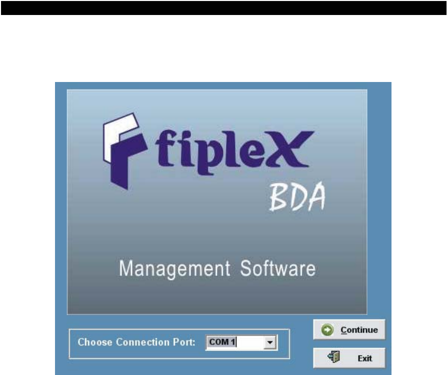
2) Choose the communication port to which you intend to connect the BDA, then click in
the continue button.
Note: In order to connect to the BDA you should use a straight serial cable with DB9 female
connectors on both sides.
21 Document FIP-BDAM-07-EN
FIPLEX • Electromagnetic Devices for Radiocommunication Systems
FIPLEX BIDIRECTIONAL AMPLIFIER - USER MANUAL
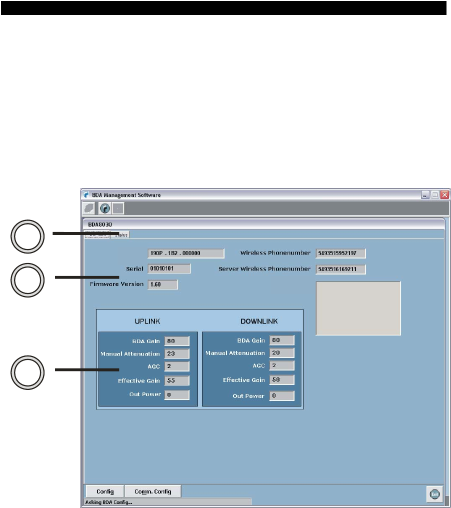
The software will start communicating automatically with the BDA showing the device and
status information.
The information is organized in two tabs (2), you can click in them to switch among the tab
sheets.
BDAINFO TAB
In (3) you can watch device specific information as BDA Type/Model, Serial Number,
firmware version, the BDA mobile number (Wireless Phone Number) and the Server
Phone Number (Server Wireless Phone Number).
2
3
4
TYPE
FILTERS
In (4) there's information about the RF power chains. You can visualize the BDA Gain,
manual attenuation, AGC attenuation level, Effective Gain and Composite Output Power
indicated in dbm.
22 Document FIP-BDAM-07-EN
FIPLEX • Electromagnetic Devices for Radiocommunication Systems
FIPLEX BIDIRECTIONAL AMPLIFIER - USER MANUAL
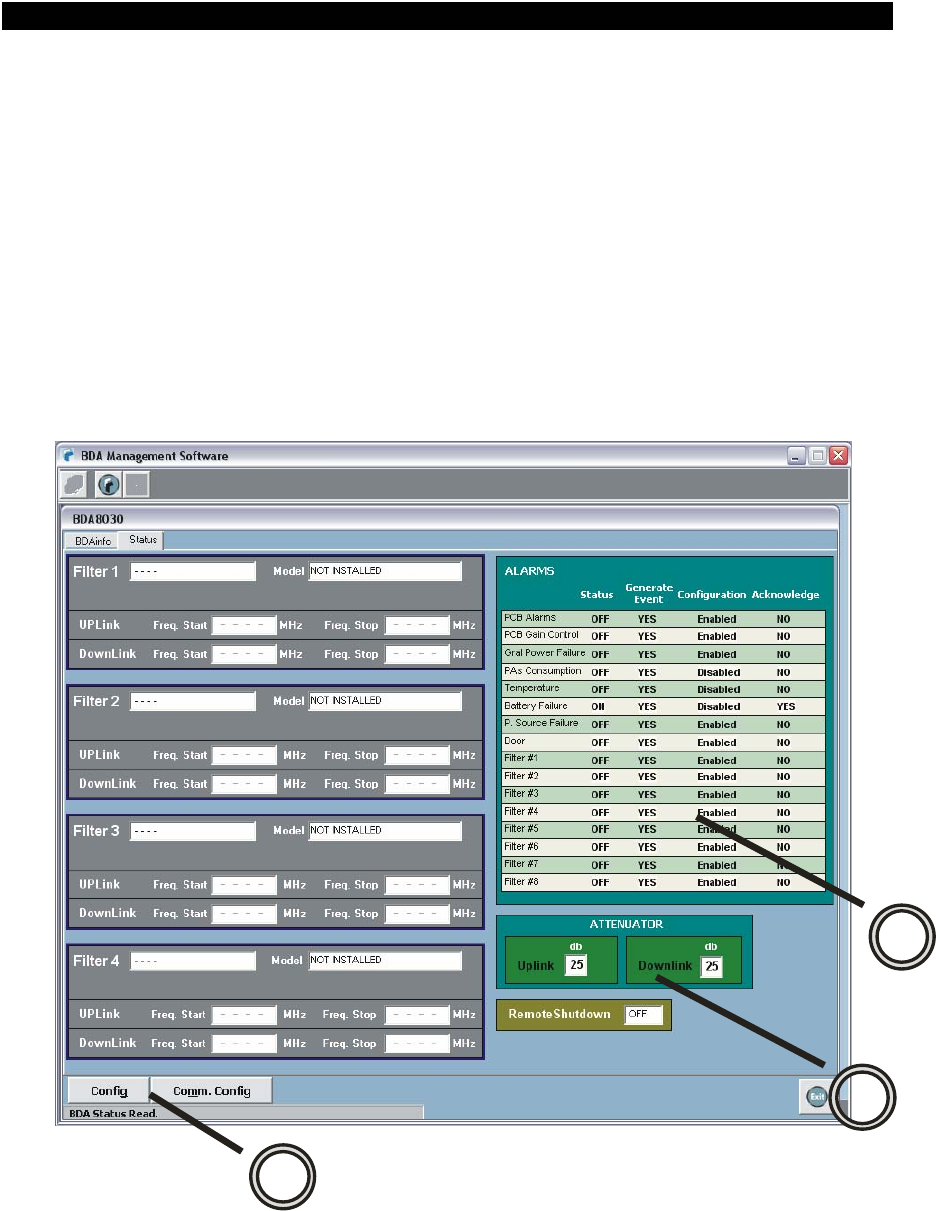
STATUS TAB
In (5) you can see the alarm status information:
. Status: ON or OFF , indicates if they are active or not.
. Generate Event: is an option to activate/deactivate if the BDA should generate an
automatic message to the Server when the alarm is activated.
. Configuration: This option is useful to enable/disable the alarm, allowing doing
maintenance on the device.
. Acknowledge: indicates if the Server acknowledged the alarm.
5
7
6
23 Document FIP-BDAM-07-EN
FIPLEX • Electromagnetic Devices for Radiocommunication Systems
FIPLEX BIDIRECTIONAL AMPLIFIER - USER MANUAL
In (6) is shown the manual attenuation information in Uplink and Downlink. You can check
if the BDA PA's are intentionally set OFF or ON with in Remote Shutdown field.
In (7) there are 2 buttons.
. Config. : once clicked it will open a Configuration TAB that allows to configure the manual
attenuation, alarms, remote shutdown and/or Heterodyne filter configurations (if present).
. Comm. Config: once clicked it will open a Communication Configuration tab allowing the
user to change the BDA Phone Number and the Server Phone Number to be properly
linked.
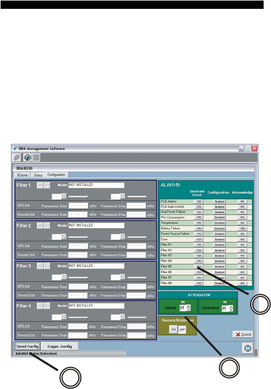
CONFIGURATION TAB
After clicking in the config button, a Configuration TAB will open as seeing in the below
image.
24 Document FIP-BDAM-07-EN
8
10 9

FIPLEX • Electromagnetic Devices for Radiocommunication Systems
FIPLEX BIDIRECTIONAL AMPLIFIER - USER MANUAL
In (8) the user can modify if an alarm is enabled/disabled, if it will generate and event
when activated and if the alarm is acknowledged or not by the server.
The acknowledge field is important when the technician goes to the BDA and solves the
problem. For example: The repeater generates and alarm event due to a power failure,
the server receives the message and acknowledges it to the BDA. If the technician solves
the problem and power is restored then it should set the Power Failure Acknowledge to
"NO" in order enable the BDA to send another message if the power fails again. If the
acknowledge remains in YES the BDA won't send a message and the OMS won't be
noticed of the alarm.
The acknowledge Field should be set to "NO" every time the alarm cause is solved.
In (8) the user can modify the manual attenuation in Uplink and Downlink. It can turn on or
off the Power Amplifier if desired.
The user can send the new desired configuration to the BDA by clicking in the "Send
Config." Button.
25 Document FIP-BDAM-07-EN
FIPLEX • Electromagnetic Devices for Radiocommunication Systems
FIPLEX BIDIRECTIONAL AMPLIFIER - USER MANUAL
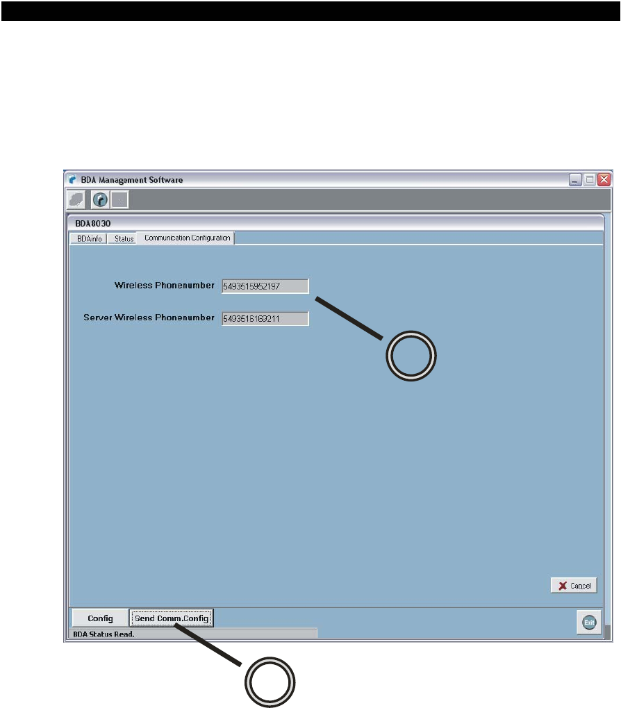
COMMUNICATION CONFIGURATION
After clicking in Comm. Config you should see a new Tab Sheet named Communication
Configuration. There you can edit the Wireless Phone Number which is the telephone
number of the modem installed in the BDA, and the Server Wireless Phone number which
is the number of the modem installed in the OMS.
12
11
The software admits only international GSM numbering plan.
Once edited you can save the new data in the BDA by clicking in the "Send Comm.
Config" button (12).
Click in EXIT to close the Communication Window.
26 Document FIP-BDAM-07-EN

FIPLEX • Electromagnetic Devices for Radiocommunication Systems
27 Document FIP-BDAM-07-EN
FIPLEX BIDIRECTIONAL AMPLIFIER - USER MANUAL