Firetide 7100-W HotPort 7010(W) Outdoor Mesh Node User Manual mesh nodes
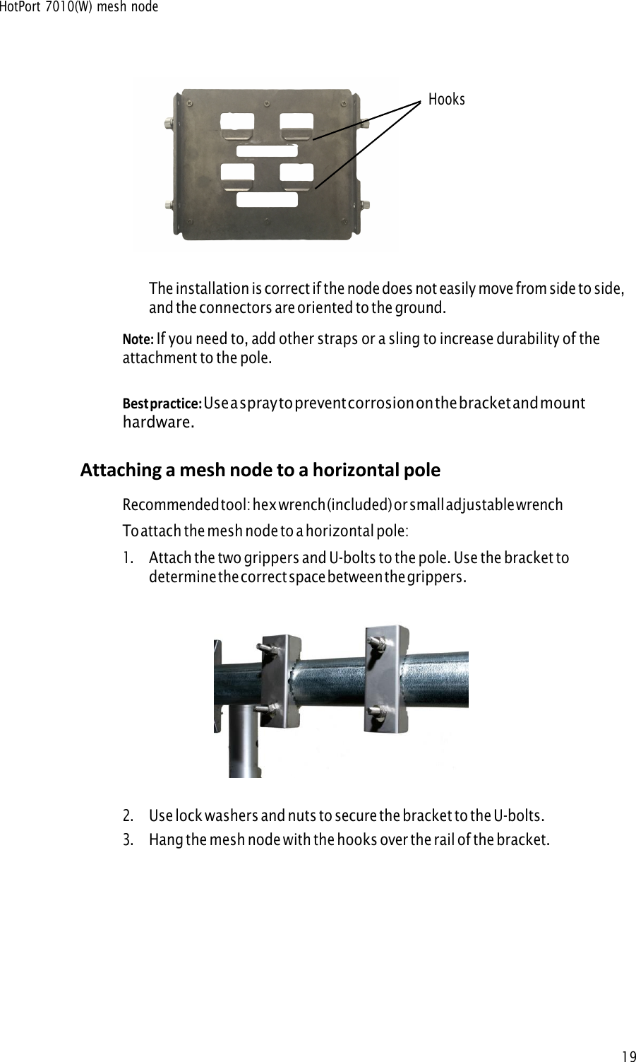
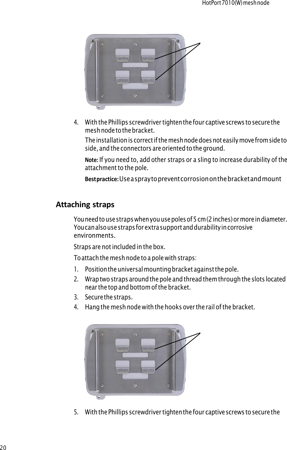
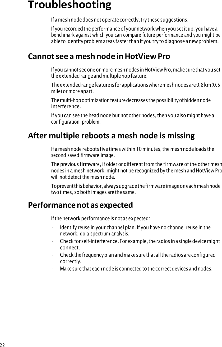
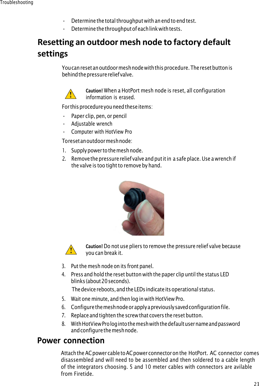
Firetide Inc. HotPort 7010(W) Outdoor Mesh Node mesh nodes
UserManual.wiki
>
Firetide
>
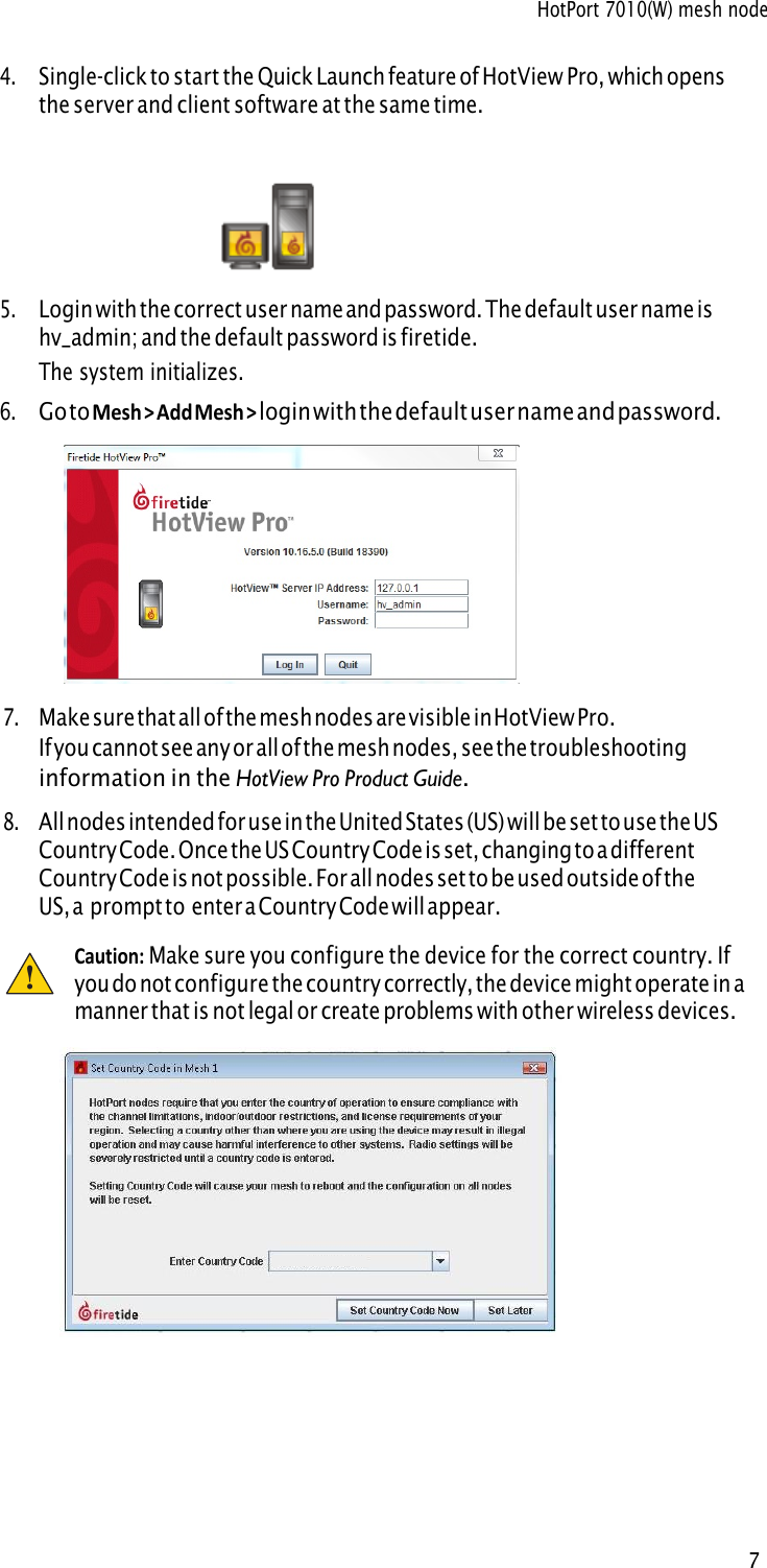
7100-W User Manual
>
User Manual
Contents
1.
User Manual
2.
User manual
User Manual
Navigation menu
Upload a User Manual
Namespaces
Wiki Guide
HTML
PDF
Info
Views
User Manual
Discussion / Help
Navigation