Firetide 7100-W HotPort 7010(W) Outdoor Mesh Node User Manual mesh nodes
Firetide Inc. HotPort 7010(W) Outdoor Mesh Node mesh nodes
Firetide >
Contents
- 1. User Manual
- 2. User manual
User Manual
HotPort
Firetide Installation Guide
HotPort 7010(W) Mesh Node
Published July, 2016
(Revised feb, 2017)

ii HotPort Firetide Installation Guide
Firetide, the Firetide logo, Reliable connectivity anywhere, HotPort and HotPoint are all
trademarks of Firetide, Inc. All other trademarks are the property of their
respective
owners.
Information in this document is subject to change without notice.
Firetide, Inc.
2105 S. Bascom Avenue, Suite 220
Campbell, CA 95008
USA
www.firetide.com
iii
About this document
This section lists the audience, purpose, summary of information, and
conventions used in this document.
Audience
This document is intended for certified professionals who install Firetide
wireless solutions.
Instructions to purchaser and installer:
This equipment must be Professionally installed. The installer is
responsible for adjusting the transmit power output of the system to
assure compliance with FCC Part 15 EIRP limits and human radiation
safety regulations.
Purpose
This document has the information and procedures necessary to install and
do
basic tests with Firetide HotPort 7010(W) mesh node.
Conventions
Certain information has special meaning for the reader. This information appears
with an icon that indicates a particular condition, such as a warning or caution,
or a label, such as “Note” or “Best Practice”.
Electrical hazards
are those environments where the danger of
electrocution is probable. This image appears before each electrical
hazard statement.
Warnings
contain safety information that you must obey. If you do
not obey the instruction in a warning, the result might include serious
injury or death. This image appears before each warning statement.
Cautions
contain information that you should obey to avoid minor
injury, inconvenience, and damage to equipment. This image appears
before each caution statement.
Notes
contain optional advice and information particular to a special case or
application.
Best practices
contain specific recommendations based on industry-standard
expectations.
Document feedback
If you find an error or content missing from this document, we want to hear
a b o u t i t . Y o u c a n s e n d y o u r f e e d b a c k a b o u t a n y o f o u r d o c u m e n t s t o
techpubs@firetide.com.
!

iv
Contacting customer support
I f y o u n e e d s u p p o r t , d e p e n d i n g o n t h e p r o b l e m , y o u m i g h t b e a s k e d f o r t h i s
information:
•
Description of the problem
•
Computer with HotView Pro and an installed management license
•
Channel and frequency plans
•
Recent spectrum analysis
•
Device topology in Google Earth (KMZ file)
•
Network map or topology plan with the names and device information
Y o u m u s t a l s o h a v e a d m i n i s t r a t o r a c c e s s t o t h e m e s h t o b e a b l e t o r e c e i v e
technical support.
The next table lists the contact information for customer support.
Worldwide customer support
Days/Hours
Contact
Americas
Monday to Friday
7 : 0 0 a m t o 5 : 3 0 p m P S T
(Pacific standard time)
http://www.firetide.com/requestsupport
1 ( 8 7 7 ) F I R E T I D E , e x t e n s i o n 2
+1 (408) 399-7771, extension 2
+1 (408) 355-7271
Africa
Monday to Friday
http://www.firetide.com/requestsupport
Asia
8 : 0 0 a m t o 5 : 3 0 p m I S T
+918040215111
Australia
(India standard time)
Fax +1(408) 317-2257
Europe
,QIRUPDWLRQWR8VHU
PPPuuurrrccchhhaaassseeerrr IIInnnssstttaaalllllleeerrr
This equipment must be Professionally installed. The installer
is responsible for adjusting the transmit power output of the
system to assure compliance with FCC Part 15 EIRP limits and
human radiation safety regulations.
Operating TX Power
allowed Power limits is as per FCC 15.407(a)
WWWaaarrrnnniiinnnggg
C
hanges or modifications not expressly approved by F
iretide
void the user's authority to operate the equipment.
Accessories or components to be used with this equipment
to use in the system, must comply with the FCC Part 15.27
Special accessories regulations. It is the responsibility of
the user to use the needed special accessories along
with the equipment.
NNNOOOTTTEEE::: This equipment has been tested and found to
comply with the limits for a Class A digital device,
pursuant to part 15 of the FCC Rules. These limits are
designed to provide reasonable protection against
harmful interference when the equipment is operated in a
commercial environment. This equipment generates,
uses, and can radiate radio frequency energy and, if
not installed and used in accordance with the
instruction manual, may cause harmful interference to
radio communications. Operation of this equipment in
a residential area is likely to cause harmful interference
in which case the user will be required to correct the
interference at his own expense.
v
Contents
About this document iii
Audience .........................................................
iii
Purpose ...........................................................
iii
Conventions ....................................................
iii
Document feedback .........................................
iii
Contacting customer support ...........................
iv
........................................................... iv
HotPort 7010(W) mesh nodes 1
Before you permanently install a HotPort 7010(W) mesh node 1
Preparing what you need to install
2
Box contents for an outdoor mesh node
2
Parts of an outdoor mesh node ........................
2
Ground screw
3
LEDs
3
Ports
3
Pressure relief valve
4
Reset button
4
Antenna connectors
4
Sun shield
5
Test before you install....................................
5
Required material that is not included
6
Required tools that are not included
6
Certification requirement
6
Doing the tests
6
HotPort 7010(W) mesh node installation 10
Tools required .................................................
10
Doing a site survey ..........................................
10
Safe installation practices ...............................
11
Preparing a mesh node for installation ...........
12
vi
Preparing earth ground ...................................
13
Installing a mesh node and antenna assembly 14
Opening the mount bracket .............................
15
Attaching the mesh node to a wall
17
Attaching a mesh node to a vertical pole
17
Attaching a mesh node to a horizontal pole 19
Attaching straps
20
Troubleshooting
22
Cannot see a mesh node in HotView Pro ...........
22
After multiple reboots a mesh node is missing 22
Performance not as expected ...........................
22
Resetting an outdoor mesh node to factory default settings 23
Power connection ............................................
23
Connector pin and cable information 24
HotPort 7010(W) AC power connector ...............
24
Custom power cables .........................................
24
Weatherproof procedures
25
Tools and materials ..........................................
25
Making weatherproof cable to node connections 25

1
HotPort 7010(W) mesh nodes
Firetide HotPort
TM
mesh nodes come from the factory with two radios that
operates in 802.11a, b, and g mode. You can enable
802.11n to use MIMO, or
configure the mesh node to operate in other modes with
HotView Pro.
Licenses enable other software features.
The next table lists the radio, included software license, and the model number
that appears in HotView Pro.
Radio
Software license
(included)
HotView Pro
model number
—
Two radios
7012
SW-7000-MIMO
Two radios, 802.11n-capable MIMO
7102
To use MIMO, you must have one MIMO license for each mesh node. One MIMO
license is sufficient for all of the radios in one mesh node. A MIMO license
enables a mesh node for all radios currently licensed or licensed in the future.
If you plan to use DFS, you must take the web-based training class. After you
pass the class, Firetide will give you login credentials so you can configure DFS
with HotView Pro.
Before you permanently install a HotPort 7010(W)
mesh
node
Before you install an outdoor mesh node in a permanent location, you need to
make sure you have all of the correct components and make sure the components
are operational.
Note:
You must complete the training program and be certified by Firetide to be
able to install Firetide products.
HotPort 7010(W) mesh nodes
2
Preparing what you need to install
To get what you need to set up a mesh node:
1.
Open the box.
2.
Remove the contents.
3.
Check the contents for damage.
If a part is missing or damaged, call your Firetide reseller.
4.
If the contents are good and correct, keep the box for future use.
Box contents for an outdoor mesh node
An outdoor model comes with these items:
•
HotPort mesh node with weatherproof caps in a NEMA-4X enclosure and
sun
shield with a two-piece mounting bracket
•
Six detachable 2.4/5 GHz omni-directional antennas
•
Two N to reverse-polarity SMA adapters
•
Mount bracket for 3.7 to 5 cm (1.5 to 2.0 inch) diameter poles or a wall
•
Mount kit
-
U-bolts, M6x1.0-80mm, with flat washers, split washers, nuts
-
Claw-tooth pole grippers
-
M6x1.0-40mm hex bolt
-
M6x1.0-20mm hex bolt
-
Hex-head socket wrench
•
AC weatherproof plug assembly (AC cable not included)
Note.
AC connector with cables can be purchased from Firetide.
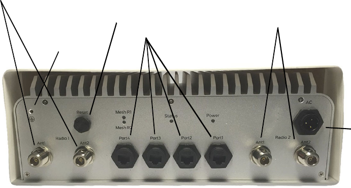
Parts of an outdoor mesh node
The next picture shows the connectors and LEDs on the bottom panel o f a
HotPort 7010(W) mesh node. Weatherproof caps protect the connectors.
For information about cables and accessories approved for use with
Firetide
devices, refer to the
Accessory Cable Guide
.
HotPort 7010(W) mesh node
3
Radio 1 connectors
G round screw
AC Power connector
Ethernet ports
Radio 2 connectors
Pressure relief valve/
Reset button
Ground screw
The ground screw is in the upper left hand corner of the bottom panel. You must
ensure adequate grounding for the mesh node.
LEDs
The bottom panel has these LEDs:
•
Power, which is a green color when the device receives power. The LED is dark
when the mesh node does not receive power.
•
Status LED:
-
Steady green color when the system passes start-up tests.
-
Dark when the mesh node is not ready.
-
Blinks green when the device resets.
•
Mesh. Each radio LED comes on when a neighbor connects to that radio. The
LEDs are dark when there is no neighbor.
Ports
Ports 1 through 4 on a HotPort 7010(W) mesh node are switch ports, similar
to the 7010 mesh node. Like the 7010 mesh node, Port 1 can receive power
from an 802.at compliant PoE source.
HotPort 7010(W) mesh node
4
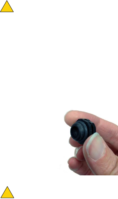
Pressure relief valve
The pressure relief valve is on the bottom panel. If you need to remove the valve
to reset the mesh node, turn it by hand or use a wrench. If you remove the valve
cover only, you can see the valve. See the next image.
Pressure relief valve
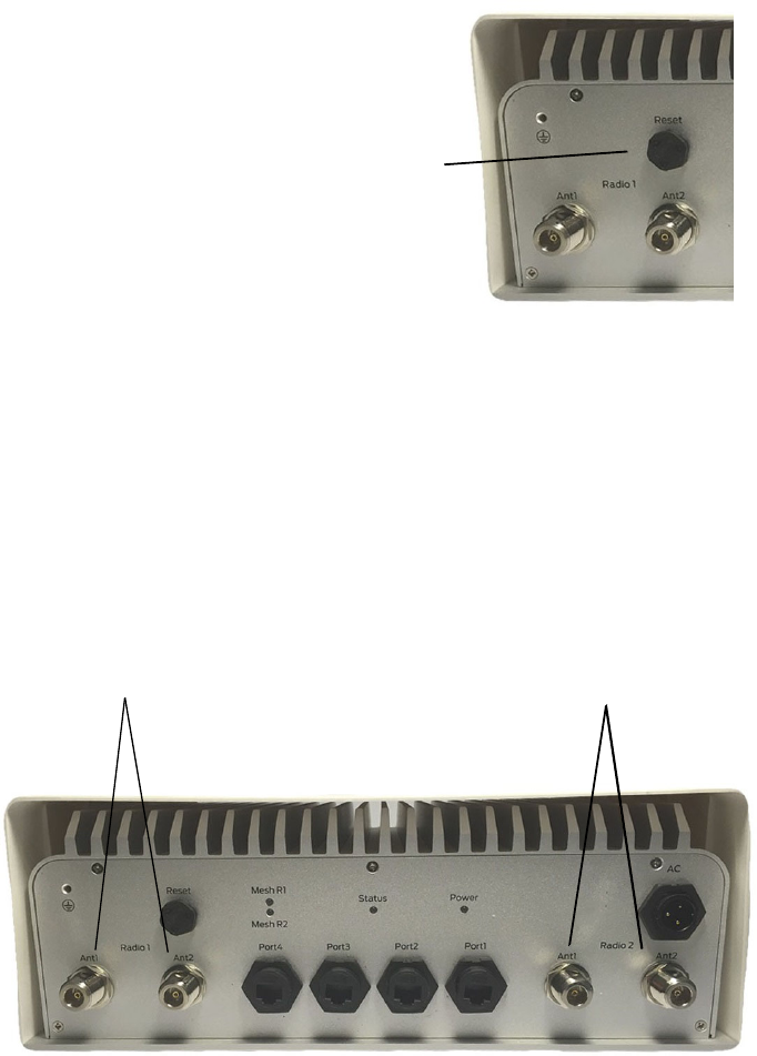
Reset button
The reset button is on the bottom panel and is covered by a pressure relief
valve. You can remove the valve to do a factory reset of the mesh node. See
“Resetting an outdoor mesh node to factory default settings” on page 24.
Antenna connectors
The next picture shows the bottom panel with two antenna connectors for each
radio
.
Radio 1 connectors
Radio 2 connectors
HotPort 7010(W) mesh node
5
Sun shield
The next picture shows the sun shield that covers the chassis. Four Phillips-head
screws hold the sun shield to the chassis.
Test before you install
You should set up and test the mesh nodes indoors on a table before you install
them in permanent locations.
The benefits of tests before you install include:
•
Make sure all of the equipment works before you install it
•
Consistent settings across mesh nodes to reduce software configuration
errors in the field
•
Test the bandwidth and make sure that the radios work
HotPort 7010(W) mesh node
6
Types of tests to do:
•
Power on each device
•
Attach all antennas and make sure you can see all devices in HotView Pro
software
•
Data and other application throughput tests
•
Learn to position the antennas with the antenna alignment tool
For more information about the antenna alignment tool, see the
Firetide
HotView Pro Reference Manual.
•
Train installation personnel
Required material that is not included
You must purchase and install a 50 ohm terminator on each unused antenna
connector of active radios. This protects the transmitter. A rubber, metal, or
plastic cap is not a replacement for a terminator.
Required tools that are not included
HotView Pro network management software and appropriate licenses are
required. Before you set up the network, you must purchase all licenses from
your Firetide distributor.
For the procedures related to license installation, refer to the
HotView Pro
Reference Manual.
Certification requirement
All people who install and manage networks that contain Firetide products must
comply with the training and certification requirements of the installation.
Doing the tests
For efficiency, you can configure six to eight mesh nodes at one time.
To do tests and capture data with HotView Pro software:
1.
Put the mesh nodes on a table.
2.
Attach the power cable to each mesh node.
3.
Attach the staging antennas to each mesh node:
-
OFDM - one antenna per radio
-
MIMO - two antennas per radio (only one radio can be tested using
the contents in the 7010(W) packaging
HotPort 7010(W) mesh node
7
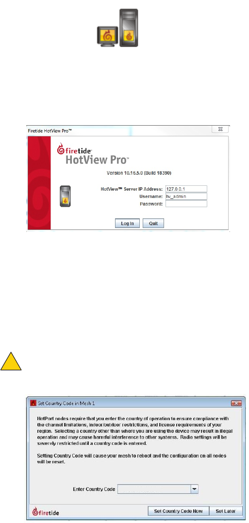
4.
Single-click to start the Quick Launch feature of HotView Pro, which opens
the server and client software at the same time.
5.
Login with the correct user name and password. The default user name is
hv_admin; and the default password is firetide.
The system initializes.
6.
Go to
Mesh > Add Mesh >
login with the default user name and password.
7.
Make sure that all of the mesh nodes are visible in HotView Pro.
If you cannot see any or all of the mesh nodes, see the troubleshooting
information in the
HotView Pro Product Guide
.
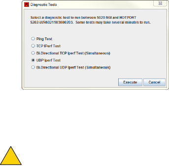
8.
All nodes intended for use in the United States (US) will be set to use the US
Country Code. Once the US Country Code is set, changing to a different
Country Code is not possible. For all nodes set to be used outside of the
US, a prompt to enter a Country Code will appear.
Caution:
Make sure you configure the device for the correct country. If
you do not configure the country correctly, the device might operate in a
manner that is not legal or create problems with other wireless devices.
!
HotPort 7010(W) mesh node
8
a.
Select the country of operation from the drop-down list.
b.
Click
Set Country Code Now
.
When you set the country code the system refreshes the mesh configuration
and gives all visible nodes the same country code. For a few minutes the
mesh nodes might appear and disappear from the graphic mesh record in
HotView Pro.
c.
Wait for three minutes for the system to finish the refresh.
9.
To configure mesh-wide settings, go to
Mesh > Configure Mesh...
-
Set the operational mode as needed.
-
Set the extended range feature if the distance between the mesh
nodes is more than 0.8 km (0.5 mile). To determine the longest link,
you measure the distance between the mesh nodes on a map, such as
Google Earth.
-
Set the hop optimization feature if there might be hidden node
interference.
Note:
For information about specific features and the configuration process, see
the HotView Pro Reference Manual.
10.
Right-click a specific mesh node to configure mesh node-specific settings if
needed.
11.
Check network throughput from end to end and for each link with several
wireless clients. For procedures, see the
HotView Pro Product Configuration
Guide
.
Note:
If you are not able to get the mesh to send and receive data, see
“Troubleshooting” on page 22.
12.
If this node will have a long RF path or if you use narrow beamwidth antennas
in the installation, set the mesh RSSI threshold to be -93 dBm.
Note:
This RSSI change prevents mesh instability because of flapping links.
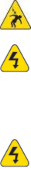
13.
Do throughput tests:
a.
Right-click on one of the two nodes between which you want to
measure performance.
b.
Select
Run Diagnostics Tools
, and select the second node from the
menu.
c.
Select the type of throughput test:
-
Ping
-
TCP Iperf and bi-directional TCP Iperf
-
UDP Iperf and bi-directional UDP
HotPort 7010(W) mesh node
9
d.
Click
Execute
.
14.
After you finish the tests, remove the staging antennas.
Caution!
The staging antennas are not rated for outdoor use.
Y o u a r e n o w r e a d y t o p e r m a n e n t l y i n s t a l l t h e m e s h n o d e s .
Power Input
100-240 VAC , 50-60 Hz, 0.8 A
Port 1 : IEEE 802.3at compliant PoE-PD
!
Environmental Specifications
Operating temperature: -20
o
C to + 60
o
C
Storage temperature: -30
o
C to +70
o
C
Humidity (non-condensing): 10% to 90%
Storage humidity (non-condensing): 5% to 95%
Max altitude: 15,000 ft (4,600 meters)

HotPort 7010(W) mesh node
10
HotPort 7010(W) mesh node installation
After you do tests and configure the mesh nodes, then you are ready to install
the mesh nodes in a permanent outdoor location.
The work process is:
1.
Gather all required tools.
2.
Do a site survey to make sure that no new safety hazards are present.
3.
Prepare safety equipment and confirm earth ground procedures.
4.
Attach the mesh nodes and antennas to poles that attach to a mast, tower,
or roof.
5.
Install the mesh node and antennas assembly and other devices, such as
cameras or access points to a permanent location.
Tools required
To install HotPort 7010(W) mesh nodes, you need to use:
•
#2 Phillips screwdriver
•
Small adjustable wrench
•
Wire cutters to cut tie wraps around cables
•
Electrical tape and butyl mastic tape to weatherproof the connectors
•
Spray to prevent corrosion
Other equipment you might need includes:
•
Ladder
•
Lift truck
•
Safety equipment
Doing a site survey
Before you install any equipment outside, check the entire site:
•
To identify possible hazards that might be new since the complete site survey
•
To identify the presence of objects that might cause interference for the
radios
Warning!
Certified professionals must install Firetide products. Failure
to install this equipment correctly can result in equipment damage,
personal injury, or death.
HotPort 7010(W) mesh node
11
Electrical shock hazard warning!
Make a plan to keep the installation
personnel safe.
Warning!
Do not install Firetide products where possible contact with
power lines can be made. Antennas, poles, towers, guy wires, or cables
can touch power lines. People can be injured or killed if they touch or
hold any part of the equipment when it contacts electric lines. Make
sure that equipment and personnel cannot directly or indirectly
contact power lines.
Warning!
Do not open the cover:
•Dangerous voltages inside.
•No serviceable parts inside.
•Refer to certified service personnel.
Safe installation practices
Best practice:
Install HotPort 7010(W) mesh nodes on poles that are a
sufficient
distance from power lines.
The horizontal distance from a tower, pole or antenna to the nearest power line
should be at least twice the total length of the pole/antenna combination. This
distance ensures that the pole will not contact a power line if it falls during or
after installation.
•
Select equipment locations that allow safe and simple installation.
•
Do not work alone.
•
Use approved non-conducting ladders, shoes, and other safety equipment.
•
Make sure all equipment is in good condition.
•
If a tower or pole begins falling, do not catch it.
•
If a wire or pole touches a power line, do not touch it.
•
Do not install antennas or towers on windy days.
•
Make sure all towers and poles are correctly grounded.
•
Make sure all electrical cables connected to antennas have lightning
arrestors.
A connection to earth ground and a lightning arrestor can prevent fire
damage or personal injury in case of lightning, static build-up, or short
circuit within the equipment connected to the antenna.
•
Use 10 AWG ground wire and corrosion-resistant connectors to connect the
base of the antenna pole or tower directly to the building protective ground
or to one or more approved grounding rods.
•
Refer to the National Electrical Code for grounding information.

HotPort 7010(W) mesh node
12
Preparing a mesh node for installation
It is easier to install all devices to one object, such as a pole, and then attach the
pole assembly to the roof. If you attach the devices to a pole attached to the roof
top, factors, such as weather, can make the installation more difficult and
dangerous.
Warning!
Only use antennas that are rated for outdoor applications.
W
arning!
Failure to comply with these installation instructions might
result in severe personal injury including electrical shock or permanent
damage to equipment.
Warning!
Make sure that all safety equipment is in good condition. Do
not use broken or damaged tools or equipment. Always use safe work
practices and obey all local and national guidance for earth ground
requirements and electricity.
Note:
Collect all tools before you install the mesh nodes.
Make sure that you have antennas rated for outdoor use. For information
about antennas and how to select them, see the
Firetide Antenna and
Accessory Guide.
Note:
Install the antenna and any other wireless devices higher than the HotPort
mesh node or access point.
1.
To a pole that you can install at a permanent outdoor site, attach these
items:
a.
Bracket for the mesh node
b.
Antenna bracket
c.
(Optional) Other devices
2.
Attach the antenna to the antenna bracket. Refer to the installation
procedures for the antenna.
Warning! Max Operating TX Power allowed Power limits is as per FCC 15.407(a).

HotPort 7010(W) mesh node
13
Preparing earth ground
Warning.
A HotPort mesh node must be correctly connected to earth
ground. Failure to do so can result in equipment damage, injury, or
death.
The product warranty does not include damage from incorrect grounding. Obey
all local building and electrical codes regarding antennas. If not available, refer
to the National Electric Code (NEC).
Earth grounding guidelines include:
•
If you attach a mesh node and antenna to a tower or pole, attach the base of
the tower pole to the building’s ground or to one or more approved
grounding rods with 10 AWG ground wire and corrosion-resistant
connectors.
•
Connect the grounding cable to rain gutters only if the rain gutter is
connected to earth ground.
•
Ground rods are copper-plated and 1.8 to 2.4 meters (6 to 8 feet) long.
•
Install all ground components in straight lines. If you must make a bend, do
not make a sharp bend.
•
Earth-to-ground should be less than or equal to 10 ohms.
•
Some salt compounds are corrosive and can cause copper ground rods to
corrode.
To prepare the soil for ground rods:
1.
If the soil contains rocks or sand, insert the ground rods into the ground
2.
Pull out the ground rods.
3.
Put in an approved ground enhancement material into the holes where the
grounding rods go.
4.
Put in the ground rods.

HotPort 7010(W) mesh node
14
Note:
Gather and take all tools and materials with you to the installation site.
Warning!
Do not install this product on a windy or rainy day.
To install a mesh node and antenna assembly in a permanent outdoor location:
1.
Safely lift and carefully put the assembly on the roof.
2.
Connecting to a MIMO antenna:
-
If your MIMO antenna has three RF connectors ( two 45 degree
connectors and one 90 degree vertical connector), then only use the
two 45 degree connectors. DO NOT use the vertical connector, and
place a 50 ohm terminator on that connector. The neighbor antenna
should also use the two 45 degree connectors, only.
-
If your one MIMO antenna has three connectors (two 45 degree
connectors and one 90 degree connector, but your neighbor
MIMO antennas has only tow connectors (two 90 degree
connectors), then mount your MIMO antenna with the two
connectors in a diamond pattern. The MIMO antenna with the the
three connectors should maintain its mount in a square pattern.
3.
Attach the pole to which the mesh node and antenna are attached to a mast,
tower, or roof.
-
Attach the cables that have integrated lightning arrestors, or attach
the cables and install lightning arrestors.
-
Make drip loops with cables.
-
Connect earth ground. See “Preparing earth ground” on page 13.
3.
Make all connectors weatherproof. See “Weatherproof procedures” on
page
25.
4.
Attach all other cables including the AC power cable.
5.
Cover all unused connectors.
6.
(Optional) Use plastic tie wraps to keep cables organized.
7.
Verify that the mesh node works:
-
Ping the IP address
-
Use one or more mesh nodes
-
Do throughput tests with HotView Pro and record the results as a
benchmark test
Installing a mesh node and antenna assembly
The process to install a mesh node to a mast or tower is the same as a roof
installation.
HotPort 7010(W) mesh node
15
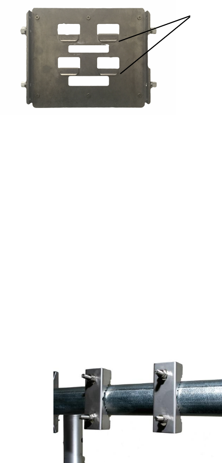
Opening the mount bracket
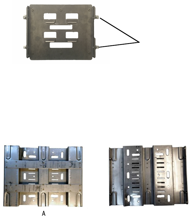
A HotPort mesh node comes with a two-piece mounting bracket. The
next
picture shows the bracket backplate that is attached to the mesh node.
Two
captive screws are on each side of this device.
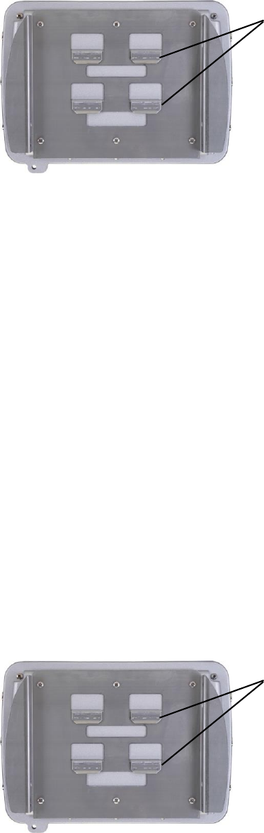
The next picture shows the bracket pieces and orientation to the mesh node.
The
mounting bracket has multiple holes and slots, so you can use bolts, straps,
or other
materials to attach the mesh node to a surface.
Image A shows the side of the mount bracket on which the node hangs. Image B
shows the back of the bracket where you thread straps or attach it to with the
mount kit to a pole or other surface.
Captive screws
B
HotPort 7010(W) mesh node
16
The mount kit includes extra nuts and bolts.
Required tools: #2 Phillips screwdriver
To open the mount bracket so you can attach the mesh node to a wall or pole:
1.
Connect the backplate bracket that is connected to the mesh node to the
(two on each side).
2.
Use a Phillips screwdriver or your fingers to loosen the four captive screws
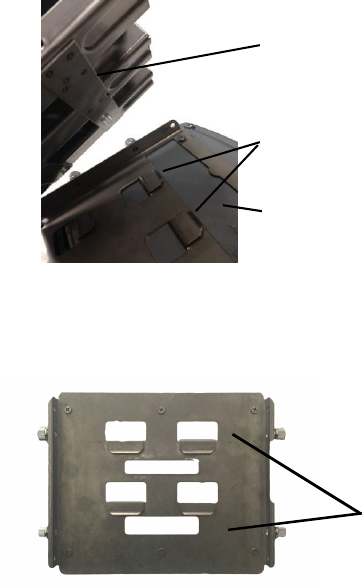
The next procedures list the steps to attach the bracket and mesh node
to
different surfaces.
Captive screws
Rail
Hooks
Mesh node chassis
to the mounting bracket on the pole.
HotPort 7010(W) mesh node
17
Attaching the mesh node to a wall
Required materials: four screws or masonry anchors
To attach a mesh node to a wall:
1.
Use four screws or masonry anchors to attach the mount bracket securely to
the wall. Put the screws or anchors in the two holes near the top and the two
holes at the bottom of the bracket.
2.
Hang the mesh node hooks on the rail.
The installation is correct if the node does not easily move from side to side, and
the connectors are oriented to the ground.
Note:
You can add other straps or a sling to increase durability of the attachment
to the wall.
Best practice:
Use a spray to prevent corrosion on the bracket and mount
hardware.
Attaching a mesh node to a vertical pole
Recommended tool: hex wrench (included) or small adjustable wrench
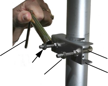
To attach the mesh node to a vertical pole:
1.
Put the two U-bolts through the holes in the gripper.
2.
On each U-bolt, put a washer, a lock washer, and a nut.
Note:
A pole with a small diameter usually requires a second nut to hold the
bracket away from the U-bolt. The end of the U-bolt must be 12 to 15 mm (0.5 to
0.6 inch) beyond the second nut.
Hex wrench
U-bolt
12 to 15 mm (0.6 inch)
Nuts for standoff
Gripper
3.
Tighten the nuts by hand.
4.
Put on the second U-bolt and gripper. Use the bracket as a guide to correctly
space the two U-bolts.
5.
Tighten the nuts with the hex wrench.
HotPort 7010(W) mesh node
18
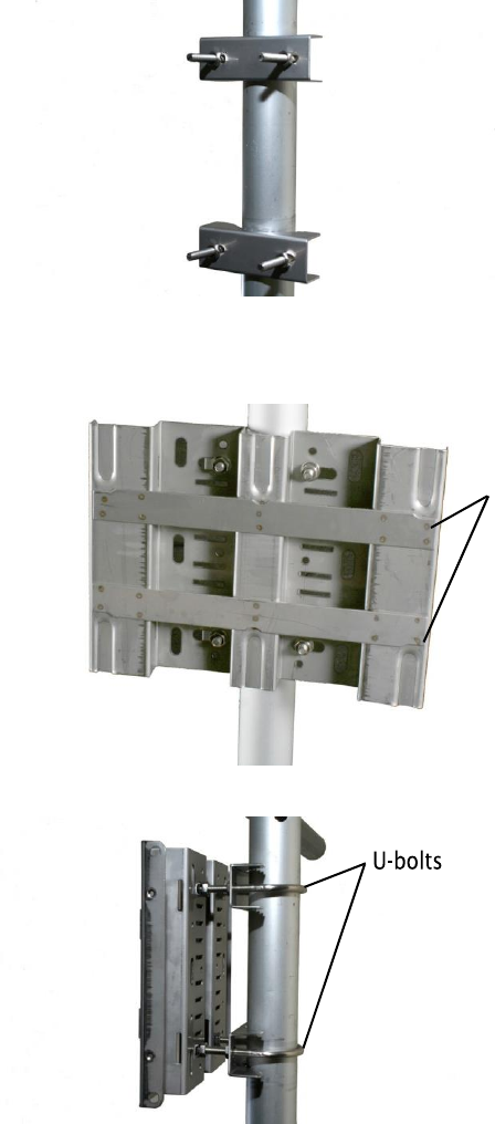
6.
Use lock washers and nuts to secure the bracket to the U-bolts.
Rails
7.
Hang the mesh node with the hooks over the rail of the bracket.
HotPort 7010(W) mesh node
19
Hooks
The installation is correct if the node does not easily move from side to side,
and the connectors are oriented to the ground.
Note:
If you need to, add other straps or a sling to increase durability of the
attachment to the pole.
Best practice:
Use a spray to prevent corrosion on the bracket and mount
hardware.
Attaching a mesh node to a horizontal pole
Recommended tool: hex wrench (included) or small adjustable wrench
To attach the mesh node to a horizontal pole:
1.
Attach the two grippers and U-bolts to the pole. Use the bracket to
determine the correct space between the grippers.
2.
Use lock washers and nuts to secure the bracket to the U-bolts.
3.
Hang the mesh node with the hooks over the rail of the bracket.
HotPort 7010(W) mesh node
20
Hooks
4 .
With the Phillips screwdriver tighten the four captive screws to secure the
mesh node to the bracket.
The installation is correct if the mesh node does not easily move from side to
side, and the connectors are oriented to the ground.
Note:
If you need to, add other straps or a sling to increase durability of the
attachment to the pole.
Best practice:
Use a spray to prevent corrosion on the bracket and mount
hardware.
Attaching straps
Y o u n e e d t o u s e s t r a p s w h e n y o u u s e p o l e s o f 5 c m ( 2 i n c h e s ) o r m o r e i n d i a m e t e r .
You can also use straps for extra support and durability in corrosive
environments.
Straps are not included in the box.
To attach the mesh node to a pole with straps:
1 .
Position the universal mounting bracket against the pole.
2 .
Wrap two straps around the pole and thread them through the slots located
near the top and bottom of the bracket.
3 .
Secure the straps.
4 .
Hang the mesh node with the hooks over the rail of the bracket.
Hooks
5 .
With the Phillips screwdriver tighten the four captive screws to secure the
enclosure to the bracket.
HotPort 7010(W) mesh node
21
The installation is correct if the node does not easily move from side to side,
and the connectors are oriented to the ground.
Note:
If you need to, add other straps or a sling to increase durability of the
attachment to the pole.
Best practice:
Use a spray to prevent corrosion on the bracket and mount
hardware.
22
Troubleshooting
If a mesh node does not operate correctly, try these suggestions.
If you recorded the performance of your network when you set it up, you have a
benchmark against which you can compare future performance and you might be
able to identify problem areas faster than if you try to diagnose a new problem.
Cannot see a mesh node in HotView Pro
If you cannot see one or more mesh nodes in HotView Pro, make sure that you set
the extended range and multiple hop feature.
The extended range feature is for applications where mesh nodes are 0.8 km (0.5
mile) or more apart.
The multi-hop optimization feature decreases the possibility of hidden node
interference.
If you can see the head node but not other nodes, then you also might have a
configuration problem.
After multiple reboots a mesh node is missing
If a mesh node reboots five times within 10 minutes, the mesh node loads the
second saved firmware image.
The previous firmware, if older or different from the firmware of the other mesh
nodes in a mesh network, might not be recognized by the mesh and HotView Pro
will not detect the mesh node.
To prevent this behavior, always upgrade the firmware image on each mesh node
two times, so both images are the same.
Performance not as expected
If the network performance is not as expected:
•
Identify reuse in your channel plan. If you have no channel reuse in the
network, do a spectrum analysis.
•
Check for self-interference. For example, the radios in a single device might
connect.
•
Check the frequency plan and make sure that all the radios are configured
correctly.
•
Make sure that each node is connected to the correct devices and nodes.
23
Troubleshooting
•
Determine the total throughput with an end to end test.
•
Determine the throughput of each link with tests.
Resetting an outdoor mesh node to factory default
settings
You can reset a n outdoor mesh node with this procedure. The reset button i s
beh ind the pressure relief valve.
Caution!
When a HotPort mesh node is reset, all configuration
information is erased.
For this procedure you need these items:
•
Paper clip, pen, or pencil
•
Adjustable wrench
•
Computer with HotView Pro
To reset an outdoor mesh node:
1.
Supply power to the mesh node.
2.
Remove the pressure relief valve and put it in a safe place. Use a wrench if
the valve is too tight to remove by hand.
Caution!
Do not use pliers to remove the pressure relief valve because
you can break it.
!
!
3.
Put the mesh node on its front panel.
4.
Press and hold the reset button with the paper clip until the status LED
blinks (about 20 seconds).
The device reboots, and the LEDs indicate its operational status.
5.
Wait one minute, and then log in with HotView Pro.
6.
Configure the mesh node or apply a previously saved configuration file.
7.
Replace and tighten the screw that covers the reset button.
8.
With HotView Pro log into the mesh with the default user name and password
and configure the mesh node.
Power connection
Attach the AC power cable to AC power connector on the HotPort. AC connector comes
disassembled and will need to be assembled and then soldered to a cable length
of the integrators choosing. 5 and 10 meter cables with connectors are avilable
from Firetide.
24
Connector pin and cable information
This section lists information about the HotPort 7010(W) connector pins and
custom
cables.
For information about antenna cables and other custom cables, see the
Firetide
Antenna and Accessory Guide.
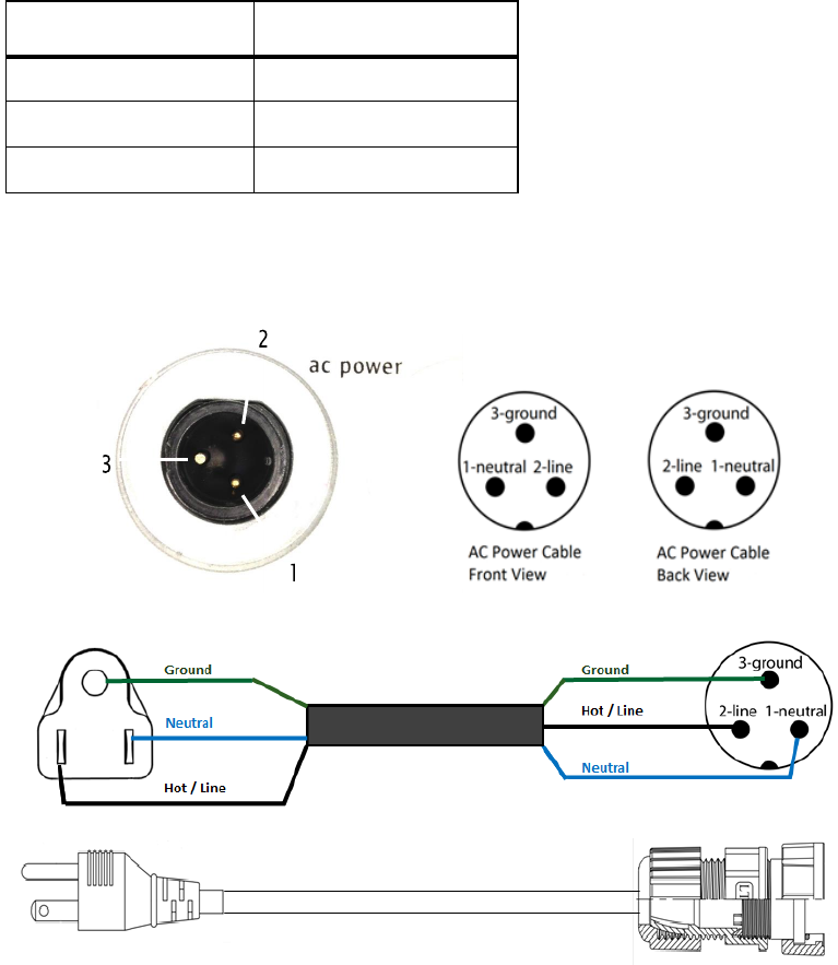
HotPort 7010(W) AC power connector
The next table lists the pins for the AC power connector.
Pin number Meaning
1
Neutral
2
Line
3
Ground
The next image shows the AC pin orientation on the device.
25
Weatherproof procedures
Cable connections become loose over time because of vibration. Loose
connections let moisture contact and erode the interface to a connector. To
prevent performance problems due to moisture damage, Firetide recommends
that you use butyl mastic to make weatherproof all outdoor connections.
Butyl mastic is a synthetic rubber sealant that you can use to make a connection
weatherproof. It is slightly sticky and stays flexible; it bonds to itself to make a
good seal. Butyl mastic and a layer of electrical tape keeps the cable assembly
clean, dry, and easy to change in the future.
Note:
To make a strong watertight connection, keep a high level of tension in the
butyl mastic when you stretch it over the cable and connector.
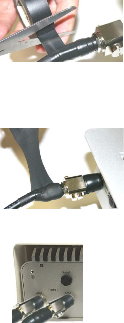
Tools and materials
To make a weatherproof connection you need the following tools and materials:
•
#2 Phillips screwdriver
•
Pliers
•
Utility knife
•
Vinyl electrical tape
Note:
Vinyl electrical tape between the cable assembly and the mastic tape
makes future changes easier than mastic tape put directly on the cable. Vinyl
electrical tape as a cover over the mastic tape prevents the mastic from melting
in hot weather.
•
Rubber splicing or mastic tape (also known as self-amalgamating, self-
sealing, self-fusing, non-vulcanized tape)
•
Pencil or wooden dowel for small clearances
•
Cleaning supplies (if necessary)
•
Laptop running HotView software
Making weatherproof cable to node connections
You need to make weatherproof two connections:
•
From the antenna cable to the lightning arrestor
•
From the lightning arrestor to the node
To make a weatherproof cable to node connection:
1.
Gather the tools and materials to do the procedure.
Weatherproof procedures
26
Mastic tape
2.
Remove the sun shield from the mesh node.
3.
Ensure that the cable and connectors are clean. Clean off oil, water, grease,
and dirt before you continue.
4.
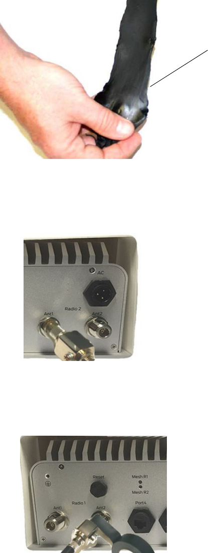
Wrap a layer of electrical tape (sticky side out) over the arrestor to node
connector and wrap approximately 1 inch (2.5 cm) of cable. Overlap the tape
by 40% with each turn.
5.
Repeat for the antenna cable to arrestor connection.
27
Weatherproof procedures
Note:
To make a watertight connection, keep tension in the butyl mastic when
you stretch it over the cable and connector.
6.
Tightly wrap a layer of mastic tape over the electrical tape. Make a 40%
overlap on each turn. Start from the base of the unit to at least 1 inch (2.5
cm) of the cable.
7.
Wra p a la y e r o f e l e c t r i c a l t a p e ( s m o o t h s id e o u t , s t i c k y si d e i n ) o ver th e
mastic tape.
8.
Wrap a second layer of electrical tape over the first layer of electrical tape.
The lightning arrestor connections are ready for installation in an outdoor
environment.
28
EIRP at 30 degree Elevation above Horizon due to Antenna
gain
EIRP at 30 degree Elevation above Horizon for 19 dBi antenna
Peak radiation gain in the direction of Sky at elevation angle above 30 degree as
measured from the Horizon for 7010(w) unit is less than 0.5dBi based upon
provided 19dBi Antenna spec sheet. When installed the 5GHz antenna
orientation will be vertically inverted to provide Omni directional Beam pattern
towards the ground plane. Refer to Antenna Spec sheet for radiation beam
pattern of 7010(w) unit.
EIRP at 30 degree Elevation above Horizon
• Maximum sum of conducted power in UNII-1 Band from all 4 antenna chain:
16.42
d
Bm
• Peak antenna gain above 30 degree elevation from Horizon as per antenna
spec sheet: 19 - 18.5=0.5dBi
• Peak EIRP above 30 degree elevation from Horizon: Maximum Conducted
Power (dBm) + Peak Antenna Gain above 30 degree elevation from Horizon (dBi)
= 16.4+0.5=16.9dBm
• Margin from FCC 15.407 limit: 21dBm-16.9dBm=4.1dB
EIRP at 30 degree Elevation above Horizon for 14 dBi antenna
Peak radiation gain in the direction of Sky at elevation angle above 30 degree as
measured from the Horizon for 7010(w) unit is less than -4dBi based upon
provided 14dBi Antenna spec sheet. When installed the 5GHz antenna
orientation will be vertically inverted to provide Omni directional Beam pattern
towards the ground plane. Refer to Antenna Spec sheet for radiation beam
pattern of 7010(w) unit.
EIRP at 30 degree Elevation above Horizon
• Maximum sum of conducted power in UNII-1 Band from all 4 antenna chain:
21.54dBm.
29
• Peak antenna gain above 30 degree elevation from Horizon as per antenna
spec sheet: 14 - 18 = -4dBi
• Peak EIRP above 30 degree elevation from Horizon: Maximum Conducted
Power (dBm) + Peak Antenna Gain above 30 degree elevation from Horizon (dBi)
= 21.54-4=17.54dBm
• Margin from FCC 15.407 limit: 21dBm-17.54dBm=3.46dB
EIRP at 30 degree Elevation above Horizon for 9 dBi antenna
Peak radiation gain in the direction of Sky at elevation angle above 30 degree as
measured from the Horizon for 7010(w) unit is less than -4dBi based upon
provided 9dBi Antenna spec sheet. When installed the 5GHz antenna orientation
will be vertically inverted to provide Omni directional Beam pattern towards the
ground plane. Refer to Antenna Spec sheet for radiation beam pattern of
7010(w) unit.
EIRP at 30 degree Elevation above Horizon
• Maximum sum of conducted power in UNII-1 Band from all 4 antenna chain:
26.77dBm
• Peak antenna gain above 30 degree elevation from Horizon as per antenna
spec sheet: 9 - 15 = -6dBi
• Peak EIRP above 30 degree elevation from Horizon: Maximum Conducted
Power (dBm) + Peak Antenna Gain above 30 degree elevation from Horizon (dBi)
= 26.77-6=20.77dBm
• Margin from FCC 15.407 limit: 21dBm-20.77dBm=0.23dB